
Related Manuals for V-Tec DT601


Summary of Contents for V-Tec DT601
- Page 1 English 2-Wire Video Outdoor Station User Manual RF CARD RF CARD DT601/ID/FE DT601F/ID/FE DT-ENG-601(F)ID-FE-V1 161108...
-
Page 2: Parts And Functions
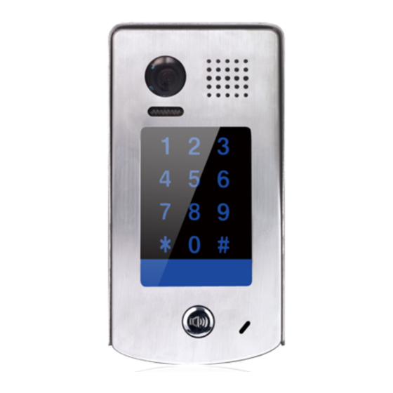
Speaker Night Light ID card window RF CARD RF CARD 30 mm Nameplate Call Button Rainy Cover Microphone 93 mm DT601/KP/FE Camera Lens Speaker Night Light ID card window RF CARD RF CARD Nameplate Call Button Microphone Screws for panel... - Page 3 S- will not be connected). 3.Door Station Mounting DT601/ID/FE Mounting Drill holes in the wall to match the size of Connect the cable correctly screws and attach the rainy cover to the wall.
- Page 4 DT601F/ID/FE Mounting Drill a hole in the wall to match the size of the Connect the cable correctly mounting box and attach to the wall. Attach the panel to the mounting box and use screws supplied to fix the panel Placing Name Label Use a screwdriver to unscrew the screw, and cock the host , then Placing Name Label.
- Page 5 4. System Wiring and Electric Lock Connection Basic Connection Code=00, DIP6=on PC6A BUS(IM) BUS(DS) L1 L2 PL S+ S- DIP Switches 1 2 3 4 5 6 Doorbell Button Switch Electric Lock Connection Door Lock Controlled with Internal Power Note: Electronic lock of Power-on-to-unlock type 1 2 3 should be used.
- Page 6 Display Driver Font Note: 1.must connect DT601(F)/ID/FE correctly before setting. 2.the parameter will be saved in DT601(F)/ID/FE automatically, so you need only set on one monitor. 3.Here we take DT47MG(the monitor) for example, please refer to the corresponding user manual.
- Page 7 Multi Door Stations Connection 4# Camera 3# Camera 2# Camera 1# Camera (Device Address:3) (Device Address:2) (Device Address:1) (Device Address:0) 100~240VAC A B C D DBC4A1 PC6A BUS(IM) BUS(DS) Impedance switch Multi Monitors Connection Basic IN-OUT Wiring Mode Code=15 Code=14 Code=0 100~240VAC PC6A...
- Page 8 With DBC4A1 Wiring Mode Impedance Code=15 Code=14 OFF ON switch Code=13 Code=12 Code=3 Code=2 Impedance OFF ON switch Code=1 Code=0 100~240VAC PC6A BUS(IM) BUS(DS) RF CARD (Device Address:0) NOTE:Here we take DT47MG(the monitor) for example.
- Page 9 5. Pan-tilt & Zoom & Panview Note that this function requires the monitor with fish-eye function to support. It is available to adjust the display mode for viewing images at a fish-eye door station by using the 5 direction pad button. When an image at a door station is displayed,move to the desired position by touching on the screen to view the image in zoom mode. Note: The edge of pantilt image will not be displayed. Screen of monitor Here are some examples: Touch...
- Page 10 1) Touch area 4: zoom area 4, the lens moves to area 6, and then return to area 4;(As below picture) Note: Touch the screen again to exit the panview mode. 2) Touch area 6: zoom area 6, the lens moves to area 4, and then return to area 6;(As below picture) Note: Touch the screen again to exit the panview mode.
- Page 11 6. ID Card Registration Introduction: • Up to 320 user cards can be registered by the door station. • Easy management with LED status and sound hints. • There are two master cards, one card and one MASTER CARD ADD MASTER card, When registered new master cards, the old master cards CARD DELETE...
- Page 12 Add User Cards: Show the Show user cards to be Show the MASTER CARD MASTER CARD card to ID card window added, one by one. card to exit. in standby mode. The color of The color of The color of background indicator background indicator background indicator...
- Page 13 Notice:1.Automatically returns to standby mode after FORMAT completed. 2.It will return to standby mode if no operation within 20s.Or press Call Button to exit the status of setting and start to call the monitor. 7.Unlock Operations Unlocking of ID Card When the registered user card has been shown to ID card window, the LED background indicator lights up, the buzzer sounds,and the electric door strike is unlocked.
-
Page 14: Specifications
• Unlocking time: 1~99s • Lock Power supply: 12Vdc, 280mA(Internal Power); • Number of relay circuits: 2(the second lock need external device to support) • Mounting: Surface mounting(DT601/ID/FE) • Flush mounting (DT601F/ID/FE) • Working temperature: -15ºC ~ +55ºC • Dimension: 182(H)×93(W)×44(D)mm(DT601/ID/FE) •... - Page 15 11. Cables Requirements The maximum distance of the wiring is limited in the DT system. Using different cables may also affect the maximum distance which the system can reach. The farest monitor monitor with two or four monitors monitor monitor DBC4A1 100~240VAC When Monitor quantity <...
- Page 16 The design and specifications can be modified without notice to the user. Right to interpret and copyright of this manual are reserved. DT-ENG-601(F)ID-FE-V1 161108...
Need help?
Do you have a question about the DT601 and is the answer not in the manual?
Questions and answers