Table of Contents
Advertisement
2-wire series
Fisheye door station with Proximity Reader
RF CARD
DT607/ID/FE-S1
RF CARD
DT607/ID/FE-S3
• Please read this manual carefully to ensure safe and correct operation
• Keep this manual well for future reference
Model D250
USER MANUAL
RF CARD
DT607/ID/FE-S2
RF CARD
DT607/ID/FE-S4
RF CARD
DT607A/ID-S4
RF CARD
DT607F/ID/FE-S4
Advertisement
Table of Contents

Related Manuals for V-Tec D250


Summary of Contents for V-Tec D250
- Page 1 2-wire series Model D250 Fisheye door station with Proximity Reader USER MANUAL RF CARD RF CARD RF CARD DT607/ID/FE-S1 DT607/ID/FE-S2 DT607A/ID-S4 RF CARD RF CARD RF CARD DT607/ID/FE-S3 DT607/ID/FE-S4 DT607F/ID/FE-S4 • Please read this manual carefully to ensure safe and correct operation...
-
Page 2: Table Of Contents
CONTENTS PARTS AND FUNCTIONS ..................3 Part Names......................3 Mounting ......................... 4 BASIC FUNCTIONS ....................6 Unlock Operations ....................6 Fisheye Camera ..................... 6 External Motion Detection ..................6 SETUP INSTRUCTIONS ..................7 Functions Setting Up ....................7 Setting Door Station Address ................. 8 Setting Door Station Calling Mode ................. -
Page 3: Parts And Functions
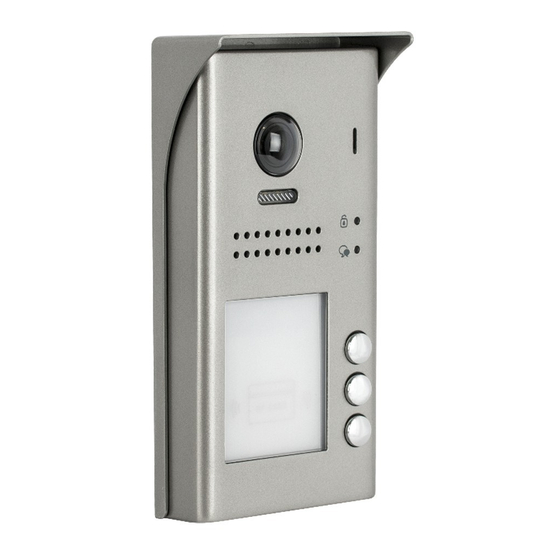
PARTS AND FUNCTIONS Parts Surface mounted [10] [11] [12] [13] Flush mounted [14] [11] [12] [13] [1] Microphone [5] Nameplate [10] Rain cover [2] UNLOCK indicator [6] Front panel [11] Mounting hook [3] Call indicator [7] Speaker [12] Connection port [4] Call button [8] Night view LED [13] Screw hole... -
Page 4: Mounting
PARTS AND FUNCTIONS Mounting The installation height is suggested to 145~160cm Surface mounted The distance between the top of main unit Rain cover ≥3mm and rain cover should be not less than 3mm. Main unit Rain cover Main unit AcDbMLeader (ACDB_MLEADER_CLASS) AcDbMLeader (ACDB_MLEADER_CLASS) 1. - Page 5 PARTS AND FUNCTIONS Terminal description Lock Control Jumper PIR Motion Detector Connect Port P L S + L 1 L 2 Main Connect Port Lock Control Jumper: To set the type of lock Motion Detector Connect Port: To connect external PIR motion detector Main Connect Port: To connect the bus line and the electric lock •...
-
Page 6: Basic Functions
BASIC FUNCTIONS Unlock Operations Unlocking with Proximity Fob/Card When registered user fob/card has been shown to the proximity Reader, the UNLOCK indicator lights up, the buzzer sounds, and the electric lock is unlocked • Authorized user fob/card will make one beep sound,and the UNLOCK indicator will lights up •... -
Page 7: Setup Instructions
SETUP INSTRUCTIONS Functions Setting Up This section explains the settings of each function,please refer to the following table To perform the settings for the function LED_UNLOCK you want,you should remove front cover. LED_TALK Please refer to the sketch KEY_SET KEY_4 Each setting will be indicated by lighting up LED_NAME KEY_3... -
Page 8: Setting Door Station Address
SETUP INSTRUCTIONS Door Station Address Setting 4 addresses can be assigned. The address can be modified either before or after installation Default address is 0. To change the address, please follow the steps: ID=0, for 1 door station ID=1, for 2 door station ID=2, for 3 door station... - Page 9 SETUP INSTRUCTIONS Each call button will respond different addresses when set in different calling mode 1.Standard calling mode (Address range 01-04 ) Call button A: call the monitor with address 01 Call button B: call the monitor with address 02 Call button C: call the monitor with address 03 RF CARD RF CARD...
-
Page 10: Setting Camera Resolution
SETUP INSTRUCTIONS Camera Resolution Setting High resolution of the camera is default. To change from High Resolution to Low Resolution, please follow the steps: In standby press Press KEY_2 button to set the Press KEY_2 button again KEY_SET button twice camera to High resolution to set the camera to Low resolution... -
Page 11: Setting Unlock Time
SETUP INSTRUCTIONS Unlock Time Setting Default unlocking time is 1s. It can be changed to desired time. Available setting range is 1s~99sec. Please, follow the steps: Press and hold KEY_2 The standby press KEY_SET button three time you holding down is the times new unlock ing time UNLOCK Indicator:ON TALK... -
Page 12: Setting Night View Led Illumination Mode
SETUP INSTRUCTIONS Setting Night View LED Illumination Mode There are 3 working modes for night view LED indicator, Normally on,Normally off and Auto. Auto is default, to change the setting, please follow the steps: In standby mode, press Press KEY_4 button to set Press KEY_4 button again Press KEY_4 button again KEY_SET button three... -
Page 13: Setting Image Display Mode
SETUP INSTRUCTIONS Setting Image Display Mode Please know that this setting is only effective for monitors which does not support man- ual operation for pan-tilt. When the monitor being called When door station calls monitor,the image will be displayed on screen,there are 3 modes for im- age displayed, Alternate switching mode,Zoom mode and Full screen mode. -
Page 14: Registering Id Card
SETUP INSTRUCTIONS Full screen mode: When answering the call, the image will be displayed on Zoom mode for 5 seconds, then switch to Full screen to remind to enter talking status. If set to forbidden mode, there is no image switching reminder at any image display mode. Activated is default, to change the setting, please follow the steps: Press KEY_3 button to Press KEY_3 button again... - Page 15 SETUP INSTRUCTIONS When power on in 10s,press Press KEY_2 button. Show the first card to ID Show the second card to ID and hold on KEY_SET button card window, set the card card window, set the card of for 3s. of MASTER CARD ADD.
- Page 16 SETUP INSTRUCTIONS Adding User Cards: Show the master card of Show user cards to be Show the master card of MASTER CARD ADD to ID added in sequence. MASTER CARD ADD again card window in standby. to exit. UNLOCK Indicator:OFF UNLOCK Indicator:OFF UNLOCK Indicator:OFF TALK Indicator:ON...
-
Page 17: Wiring
WIRING Connecting Electric Lock Door Lock Controlled with Internal Power 1 2 3 1.Electric Power-on-to-unlock type should be used Jumper position on 2&3 2.The door lock is limited to 12V, and holding current must be less than 250mA PL S+ S- 3.The jumper should be placed in position 2 and 3 before connecting 4. -
Page 18: Connecting Basic One-To-One
WIRING 1-Monitor Kit Connection ID=0 Code=1, DIP6=on 100~240VAC PC6A RF CARD BUS(IM) BUS(DS) L1 L2 PL S+ S- DIP Switches 1 2 3 4 5 6 • The door station default is Standard mode. Button will call monitor with User Code 1 Connecting Multiple Door Stations door station door station... -
Page 19: Connecting Multi Monitors
WIRING Connecting Multiple Monitors via daisy chain Basic IN-OUT Wiring in Standard Mode • The door station is also compatible with other monitors which are provided by our Code=1, DIP6=on company. (Slave 3) • Please set door station into group calling mode if there is more than 4 monitors in villa(Refer to Page 9) •... - Page 20 WIRING Star Topology Wiring With DBC4A1 in Standard Mode Code=1,DIP6=on Code=2,DIP6=on Impedance OFF ON switch Code=3,DIP6=on Code=4,DIP6=on 100~240VAC PC6A DBC4A1 BUS(IM) BUS(DS) Optional functional module BDU bus amplifier module RLC staircase light controller module DBC4A1 2/4 inputs branch distributor RF CARD ID=0 •...
-
Page 21: Appendix
APPENDIX Precautions • Please clean the unit with soft cotton cloth, don't use the organic impregnant or chemical clean agent. If necessary, please use a little pure water or dilute soap water to clean the dust. • The unit is weather resistant. However do not spray high pressure water on access control keypad directly. -
Page 22: Cables And Requirments
APPENDIX Cables and Requirments The maximum distance of the wiring is limited in the DT system. Using different cables may also affect the maximum distance which the system can reach. Basic IN-OUT Wiring Mode Cable and distance(unit:m) Cable Usage ≤2 IM ≤16 IM Twisted cable 2x0.75mm Twisted cable 2x1mm... - Page 23 APPENDIX Star Topology Wiring Mode With DBC4A1 DBC4A1 PC6A Cable and distance(unit:m) Cable Usage Twisted cable 2x0.75mm Twisted cable 2x1mm RF CARD -23-...
- Page 24 The design and specifications can be changed without notice to the user. Right to interpret and copyright of this manual are preserved.
Need help?
Do you have a question about the D250 and is the answer not in the manual?
Questions and answers