Table of Contents

Related Manuals for V-Tec DT607C Series


Summary of Contents for V-Tec DT607C Series
- Page 1 DT-ENG-DT607C-V1 / 201705 2 WIRE SYSTEM DT607C Series USER MANUAL DT607C-S1 DT607C-S2 DT607C-S3 DT607C-S4 • Please read this manual carefully to ensure safe and correct operation. • Keep this manual well for future reference.
-
Page 3: Table Of Contents
CONTENTS PARTS AND FUNCTIONS ..................1 Part Names......................1 Mounting ......................... 1 External Motion Detection ..................2 SETUP INSTRUCTIONS ..................3 Functions Setting Up ....................3 Setting Door Station Address ................. 4 Setting Door Station Calling Mode ................. 4 Setting Unlock Mode ....................6 Setting Unlock Time.................... -
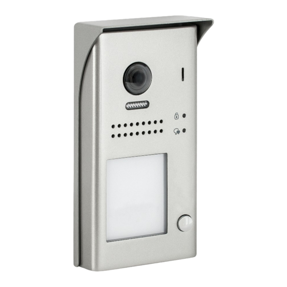
Page 4: Parts And Functions
PARTS AND FUNCTIONS Part Names [11] [10] [12] [13] [1] Microphone [6] Front panel [10] Rainy cover [2] UNLOCK indicator [7] Speaker [11] Mounting hook [3] CALL indicator [8] Night view LED [12] Connection port [4] Call button [9] Camera lens [13] Screw hole [5] Nameplate Mounting... -
Page 5: External Motion Detection
PARTS AND FUNCTIONS Terminal description Lock Control Jumper PIR Motion Detector Connect Port P L S + L 1 L 2 Main Connect Port Lock Control Jumper: To select the lock type. Motion Detector Connect Port: To connect external PIR motion detector. Main Connect Port: To connect the bus line and the electronic locks. -
Page 6: Setup Instructions
SETUP INSTRUCTIONS Functions Setting Up This section explains the settings of each function,please refer to the following table: To perform the settings for the function LED_UNLOCK you want,you should move away the metal LED_TALK front panel. Please refer to the sketch KEY_SET map. -
Page 7: Setting Door Station Address
SETUP INSTRUCTIONS Setting Door Station Address Total 4 addresses can be configured. It can be modified either before or after installation. 0 is default, to change the setting, please follow the steps: ID=0,1 door station ID=1,2 door station ID=2,3 door station ID=3,4 door station In standby mode, press... - Page 8 SETUP INSTRUCTIONS Each call button will respond different addresses when set in different calling mode. Refer to the followings for more informations. 1.Standard calling mode(Address range 01-04 by default) Call buttonA: call the monitor with address 01 by default. Call buttonB: call the monitor with address 02 by default. Call buttonC: call the monitor with address 03 by default.
-
Page 9: Setting Unlock Mode
SETUP INSTRUCTIONS Setting Unlock Mode There are 2 unlock modes, Normally opened and Normally closed. Normally opened is default, to change the setting, please follow the steps: In standby mode, press Press KEY_1 button to set Press KEY_1 button again KEY_SET button three the unlock mode to to set the unlock mode to... -
Page 10: Setting Nameplate Illumination Mode
SETUP INSTRUCTIONS Setting Nameplate Illumination Mode There are 3 illumination modes for nameplate indicator, Normally on,Normally off and Auto. Normally on is default, to change the setting, please follow the steps: Press KEY_3 button to set Press KEY_3 button again Press KEY_3 button again In standby mode, press KEY_SET button three... -
Page 11: Setting Ring-Back Tone
SETUP INSTRUCTIONS Setting Ring-back Tone If allow ring-back tone, press the call button to call monitor, a ring-back call tone can be heard from door station. There are 3 ring-back call tones, Ringing one time,Ringing continuously and No ring-back tone. Ringing one time is default, to change the setting, please follow the steps: In standby mode, press Press KEY_1 button to set... -
Page 12: Wiring
WIRING Connecting Electric Lock Door Lock Controlled with Internal Power 1 2 3 1.Electronic lock of Power-on-to-unlock type should be used. Jumper position on 2&3 2.The door lock is limited to 12V, and hold- ing current must be less than 250mA. PL S+ S- 3.The jumper should be placed on position 2 and 3 before connecting. -
Page 13: Connecting Basic One-To-One
WIRING Connecting Basic One-to-one ID=0 Code=1, DIP6=on 100~240VAC PC6A BUS(IM) BUS(DS) L1 L2 PL S+ S- DIP Switches 1 2 3 4 5 6 • The door station work in Standard mode in this situation. Refer to Page 8 in detail. •... -
Page 14: Connecting Multi Monitors
WIRING Connecting Multi Monitors Basic IN-OUT Wiring in Standard Mode • The door station is also compatible with other monitors which are provided by our Code=1, DIP6=on company. (Slave 3) • Please set door station into group calling mode if there is more than 4 monitors in villa(Refer to Page 8) •... - Page 15 WIRING Star Topology Wiring With DBC4A1 in Standard Mode Code=1,DIP6=on Code=2,DIP6=on Impedance OFF ON switch Code=3,DIP6=on Code=4,DIP6=on 100~240VAC PC6A DBC4A1 BUS(IM) BUS(DS) Optional functional module BDU bus amplifier module RLC staircase light controller module DBC4A1 2/4 inputs branch distributor ID=0 •...
-
Page 16: Appendix
APPENDIX Precautions • Please clean the unit with soft cotton cloth, don't use the organic impregnant or chemical clean agent. If necessary, please use a little pure water or dilute soap water to clean the dust. • The unit is weather resistant. However do not spray high pressure water on access control keypad directly. -
Page 17: Cables And Requirments
APPENDIX Cables and Requirments The maximum distance of the wiring is limited in the DT system. Using different cables may also affect the maximum distance which the system can reach. Basic IN-OUT Wiring Mode Cable and distance(unit:m) Cable Usage ≤2 IM ≤16 IM Twisted cable 2x0.75mm Twisted cable 2x1mm... - Page 18 APPENDIX Star Topology Wiring Mode With DBC4A1 DBC4A1 PC6A Cable and distance(unit:m) Cable Usage Twisted cable 2x0.75mm Twisted cable 2x1mm -15-...
- Page 19 Note -16-...
- Page 20 DT-ENG-DT607C-V1 The design and specifications can be changed without notice to the user. Right to interpret and copyright of this manual are preserved.
Need help?
Do you have a question about the DT607C Series and is the answer not in the manual?
Questions and answers