
Related Manuals for AMS XL200 Series


Summary of Contents for AMS XL200 Series
- Page 1 XL200 Series Open Loop Controller Version 3.18 Installation Guide & Technical Reference...
- Page 2 Copyright © 2007 − AMS Controls, Inc. All rights reserved. The information contained in this document is proprietary to AMS Controls, Inc., and is not to be reproduced in any form without the specific written authorization of AMS Controls, Inc.
-
Page 3: Table Of Contents
XL200 Series OL Controller Installation Guide & Technical Reference Table of Contents CHAPTER 1: INSTALLATION OVERVIEW ...............1 CHAPTER 2: SYSTEM TYPE DESCRIPTION..............3 ...........................3 VERVIEW Open Loop Flying Cutoff with Flying Punch Press..............4 Open Loop Feed-to-Stop, Shear-Only ..................5 CHAPTER 3: MODEL CUSTOMIZATION................6 ........................6... - Page 4 XL200 Series OL Controller Installation Guide & Technical Reference Asynchronous Print Detect ....................38 Hole Detect ..........................38 ............................39 UTPUTS Fast, Slow, Reverse, and Forward..................39 Run ............................39 Shear/Press Down........................39 Shear/Press Up ........................40 Shear/Press Die Boost ......................40 Item Complete ........................40 Stacker............................40 ...........................41 IGNAL ORTS Analog Output #1 (Proportional to Line Velocity) ..............41...
- Page 5 XL200 Series OL Controller Installation Guide & Technical Reference ....................100 NPUTS AND UTPUTS Test Jog outputs ........................100 Test Encoder Direction ......................101 Test Shear Outputs.......................101 Initial Run & Calibration.....................101 ....................102 LYING UTOFF ALIBRATION What is Shear Reaction?......................102 Setting Shear and Boost Reaction Times ................104 ......................110...
-
Page 7: Chapter 1: Installation Overview
XL200 Series OL Controller Installation Guide & Technical Reference Chapter 1: Installation Overview When installing an XL 200OL controller, you must have certain specific information available concerning the controller and your line. Once you have that information, you can install the controller following the procedures outlined in this guide. - Page 8 XL200 Series OL Controller Installation Guide & Technical Reference...
-
Page 9: Chapter 2: System Type Description
• Flying cutoff machines, where material does not stop for press operations and the cutoff or punching die moves with the material during the press cycle. Combinations The XL200 Series controller can be configured to operate machines of each type, as well as numerous variations and combinations. Typical applications include:... -
Page 10: Open Loop Flying Cutoff With Flying Punch Press
XL200 Series OL Controller Installation Guide & Technical Reference • Open Loop Flying Cutoff with Flying Punch Press • Open Loop Feed-to-Stop, Shear-Only Open Loop Flying Cutoff with Flying Punch Press In a flying die application, the punch press and cutoff move with the material, and the material is not stopped for press operation. -
Page 11: Open Loop Feed-To-Stop, Shear-Only
XL200 Series OL Controller Installation Guide & Technical Reference Open Loop Feed-to-Stop, Shear-Only Feed-to-stop machines stop the material for each press operation and the die remains at a fixed location. A simple feed-to-stop machine is shown in Figure 2. Material Flow... -
Page 12: Chapter 3: Model Customization
The factors that influence which software model should be selected and how it should be configured for a particular application include: • The number of presses on the machine that the XL200 Series controller must control. • Whether the machine operates in a flying-cut or feed-to-stop mode. -
Page 13: Model Types And Options
XL200 Series OL Controller Installation Guide & Technical Reference Model Types and Options The following tables provide configuration instructions for each software model in each operating mode. Input and output definitions are provided for each model type are also listed. - Page 14 XL200 Series OL Controller Installation Guide & Technical Reference Model Options Model Option Description Expanded Gag Board (E) Allows the XL200 Series controller to communicate with up to 4 additional output cards for controlling machines with a large number of gagged punch tools.
- Page 15 Combining Model Options Several model options may be combined together as long as their functionality does not conflict with each other. Some examples of XL200 Series controller software model names are: • XL200BP – XL200 model type with the Bundle Print and Print on Part model options enabled.
-
Page 16: Configuration Switch Settings
XL200 Series OL Controller Installation Guide & Technical Reference • XL212AABEMS – XL212 model type with the Analog Speed Logic, Bundle Printer, Expanded Gag, Extended Macro, and Auxiliary Controller options enabled. Configuration Switch Settings Each model type must be configured for one of several different operating modes, depending on the machine’s requirements. -
Page 17: Model Types: Xl202, Xl206, Xl212, Xl202H, Xl206H, & Xl212H
XL200 Series OL Controller Installation Guide & Technical Reference Notes: The Shear Boost functionality can not be enabled for a feed-to-stop shear. The Punch Boost functionality can not be enabled for feed-to- stop punch press. The Auto-Crop functionality is only available for model type XL200 and can not be enabled when the controller is configured for a punch press. - Page 18 (XL202 – 2 outputs, XL206 – 6 outputs, XL212 – 12 outputs). For example: If model type XL206 is configured for a machine with 2 presses (switch #4 On), The XL200 Series controller provides outputs for the shear press, one punch press, and four gagged tools.
-
Page 19: Model Type: Xl266
XL200 Series OL Controller Installation Guide & Technical Reference Model Type: XL266 Switch # Reserved –Set to Off Reserved –Set to Off Reserved –Set to Off Reserved –Set to Off Reserved –Set to Off Reserved –Set to Off Reserved –Set to Off Reserved –Set to Off... -
Page 20: Input/Output Definitions
XL200 Series OL Controller Installation Guide & Technical Reference Input/Output Definitions Only after the XL200 Series controller’s software model is identified and the configuration dip-switches have been set, the definitions for all inputs and outputs are known. The following tables define how the configuration dip-switches are used for each model type. - Page 21 XL200 Series OL Controller Installation Guide & Technical Reference Hole Detect Reserved Notes: Input 21 (Asynchronous Print Detect) and Output 8 (Part Print Trigger) are only available when the Print on Part model option is enabled. Input 24 (Hole Detect) is only available for model type XL200H.
-
Page 22: Model Type: Xl200L (Alternating Punch Option Enabled)
XL200 Series OL Controller Installation Guide & Technical Reference Model Type: XL200L (Alternating Punch Option Enabled) I/O # Inputs Outputs Jog Forward Fast Jog Reverse Slow Reverse Reserved Setup Lockout Item Complete Manual Shear Forward Manual Punch Reserved Tail Out / Sheet Detect... -
Page 23: Model Types: Xl202 & Xl202H
XL200 Series OL Controller Installation Guide & Technical Reference All inputs and outputs that pertain to the punch press (press 1) are not active when the controller’s configuration dip-switches are set to disable the punch press functionality. Model Types: XL202 & XL202H... - Page 24 XL200 Series OL Controller Installation Guide & Technical Reference Notes: Input 21 (Asynchronous Print Detect) and Output 8 (Part Print Trigger) are only available when the Print on Part model option is enabled. Input 24 (Hole Detect) is only available for model type XL202H.
-
Page 25: Model Types: Xl206 & Xl206H
XL200 Series OL Controller Installation Guide & Technical Reference Model Types: XL206 & XL206H I/O # Inputs Outputs Jog Forward Fast Jog Reverse Slow Reverse Reserved Setup Lockout Item Complete Manual Shear Forward Manual Punch Reserved Tail Out / Sheet Detect... - Page 26 XL200 Series OL Controller Installation Guide & Technical Reference The controller will provide as many Press Down outputs as required based on the number of presses defined by the configuration dip- switch setting. The remaining outputs will be defined as gags.
-
Page 27: Model Types: Xl212 & Xl212H
XL200 Series OL Controller Installation Guide & Technical Reference Model Types: XL212 & XL212H I/O # Inputs Outputs Jog Forward Fast Jog Reverse Slow Reverse Reserved Setup Lockout Item Complete Manual Shear Forward Manual Punch Reserved Tail Out / Sheet Detect... - Page 28 XL200 Series OL Controller Installation Guide & Technical Reference The controller will provide as many Press Down outputs as required based on the number of presses defined by the configuration dip- switch setting. The remaining outputs will be defined as gags.
-
Page 29: Model Type: Xl200Dlp (With The Alternating Punch & Print On Part Options Enabled)
XL200 Series OL Controller Installation Guide & Technical Reference Model Type: XL200DLP (with the Alternating Punch & Print on Part Options Enabled) I/O # Inputs Outputs Jog Forward Fast Jog Reverse Slow Reverse Reserved Setup Lockout Item Complete Manual Shear... -
Page 30: Model Type: Xl266
XL200 Series OL Controller Installation Guide & Technical Reference Input 24 (Asynchronous Print Detect) and Output 6 (Part Print Trigger) are only available when the Print on Part model option is enabled. Model Type: XL266 I/O # Inputs Outputs Jog Forward... - Page 31 XL200 Series OL Controller Installation Guide & Technical Reference Input 21 (Asynchronous Print Detect) and Output 8 (Part Print Trigger) are only available when the Print on Part model option is enabled. The controller will provide as many Press Down outputs as required based on the number of presses defined by the configuration dip- switch setting.
-
Page 32: Chapter 4: Hardware & Installation
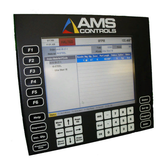
• Sourcing Outputs with Sinking Inputs (optional) – identified with black connectors. The XL200 Series controller has six 16-pin terminal-style connectors on its back surface and several additional interface ports on its top surface. Figure 5 through Figure 6 show the controller’s keypad and display, and the locations of all of the... - Page 33 XL200 Series OL Controller Installation Guide & Technical Reference Figure 3: XL200 Series Controller - Front View...
-
Page 34: Back Panel Connections
XL200 Series OL Controller Installation Guide & Technical Reference Back Panel Connections Figure 4: XL200 Series Controller - Back View The six connectors on the back surface provide the following connection points: • Connector A - 24VDC CPU Power Supply input, Encoder 1 input, Encoder 2 input. -
Page 35: Additional Connections
The interface ports on top provide the following connection points: • SVGA Port (15-pin) - for connection to an industry-standard SVGA monitor. • Scanner/Debugger Port (RS232, 9-pin) - for connection to an AMS-approved barcode scanner. This port is also used for updating the controller’s firmware (a laptop computer with the appropriate software application required). -
Page 36: Power Requirements
XL200 Series OL Controller Installation Guide & Technical Reference Power Requirements CPU Power Supply A high-quality, regulated supply is recommended for use with the XL200 Series controller. • 24 Volts DC (+/- 10%) • 2.5 Amps, minimum I/O Power Supply A separate, non-regulated power supply is sufficient for the Input/Output supply voltage. -
Page 37: Encoder Installation
Diagrams (page 125) for examples of typical XL200 Series controller wiring diagrams. Encoder Installation Mounting the encoder properly is the most important aspect of the XL200 Series controller installation because accurate material tracking is required for the controller to produce consistently accurate parts. Here are few guidelines to... - Page 38 XL200 Series OL Controller Installation Guide & Technical Reference END VIEW END VIEW BENT SHAFT TOO LITTLE PRESSURE TOO MUCH PRESSURE TOP VIEW END VIEW WOBBLE WHEEL NOT SQUARE TO MATERIAL WHEEL NOT PARALLEL TO MATERIAL FLOW Figure 6: Improper Encoder Mounting...
- Page 39 XL200 Series OL Controller Installation Guide & Technical Reference AMS Controls Encoders, Wheels, & Brackets AMS Controls provides specially designed encoders, wheels, and mounting brackets for use with all XL200 Series controllers.
-
Page 41: Chapter 5: Input & Output Descriptions
Jog Reverse input is activated. The Jog Reverse input is typically activated by a momentary push-button. Run causes the XL200 Series controller to enter and exit the run mode. When activated, the controller enters the run mode as long as valid order data is programmed and no error conditions are detected (See the XL200 Series Operator’s guide for more details about entering the Run Mode). -
Page 42: Shear Complete
Setup Lockout The Setup Lockout input is used to prevent personnel from accessing critical data in the XL200 Series controller. When active, machine operator is not allowed to change most setup parameter and is restricted from performing certain functions. The Setup Lockout is typically wired to a key-switch and it is recommended that the key be held by a maintenance supervisor. -
Page 43: Manual Punch
Manual Shear input is typically wired to a momentary push-button. Manual Punch Only available on XL200 Series controllers that are configured for one or more punch presses and/or one or more gagged presses, the Manual Punch input causes the controller activate one its press outputs and execute a press cycle. Which press output turns on may depend on the value of a setup parameter Tool Selected for Manual Press. -
Page 44: Press (N) Up Complete
XL200 Series OL Controller Installation Guide & Technical Reference Press (n) Up Complete Only available for Model Type XL266, the XL200 Series controller provides a Press Up Complete input for each press on the machine based on the software model type and configuration dip-switch settings. Each Press Up Complete input functions similar to how the Shear Up Complete input works. -
Page 45: Outputs
Outputs Fast, Slow, Reverse, and Forward These four outputs are referred to as the motion outputs of the XL200 Series controller. They are intended to control the motion of the machine. The table below describes the state of each of these outputs while the controller is in various... -
Page 46: Shear/Press Up
Shear/Press Complete input. Shear/Press Up The Shear/Press Up outputs may be available depending on the XL200 Series controller’s software model and configuration dip-switch setting. The output should be directly connected to a solenoid that drives the shear/punch press upward during the return stroke of its cycle. -
Page 47: Signal Ports
Comm. Port “A” (RS485 Eclipse Port) This RS485, serial communication port is solely intended to be connected to an office computer running the AMS Controls Eclipse software application. See the Eclipse User’s/Installation guides for more details. Comm. Port “B” (RS485 Auxiliary Port) -
Page 48: Comm. Port "D" (Rs422 High Speed Port)
XL200 Series OL Controller Installation Guide & Technical Reference Comm. Port “D” (RS422 High Speed Port) This RS422 High-Speed communication port can be connected to a PLC that complies with the industry-standard MODBUS serial communication specification. See the XL200 Series Auxiliary Devices manual for more details. -
Page 49: Chapter 6: Setup Parameters
XL200 Series OL Controller Installation Guide & Technical Reference Chapter 6: Setup Parameters Once the XL200 Series controller has been customized with a specific software model and a unique configuration dip-switch setting, it still must be tailored to the machine’s operation using setup parameters. -
Page 50: Machine Parameters Menu
XL200 Series OL Controller Installation Guide & Technical Reference Figure 7: Setup screen The Setup screen is divided into two sections. Menus are listed in the right-hand section, while the parameters for the selected menu display in the right-hand section. -
Page 51: Shear Boost Dwell
XL200 Series OL Controller Installation Guide & Technical Reference Shear Dwell Down Range: 0.001 to 30.000 Seconds Applies to: All configurations The Shear Dwell Down parameter defines the length of time that the controller turns on the Shear Down output during a manual or automatic shear cycle. This... - Page 52 XL200 Series OL Controller Installation Guide & Technical Reference Shear Reaction Range: 0.000 to 1.000 Seconds Applies to: Flying-Cutoff Configurations The Shear Reaction parameter is used to compensate for the time delay between the instant that the controller’s Shear Down output turns on and when the shear die makes contact with the material.
- Page 53 0.001 to 30.000 Seconds Applies to: Configurations including one or more punch presses The XL200 Series controller provides one Press (n) Dwell Down setup parameter for each punch press on the machine based on the model type and configuration switch setting. The functionality is very similar to that of the Shear Dwell Down parameter, only with respect to a punch press.
- Page 54 Applies to: Configurations including one or more punch presses when Press Boost outputs are disabled The XL200 Series controller provides one Press (n) Dwell Up setup parameter for each punch press on the machine based on the model type and configuration switch setting.
- Page 55 Applies to: All configurations including one or more punch presses in non- stopping mode The XL200 Series controller provides one Press (n) Boost Enable Velocity setup parameter for each punch press on the machine based on the model type and configuration switch setting.
-
Page 56: Run Mode Options
Applies to: Model Type XL266 Only when configured for one or more punch presses The XL200 Series controller provides one Expect Press Up Complete (n) setup parameter for each punch press on the machine based on the model type and configuration switch setting. - Page 57 XL200 Series OL Controller Installation Guide & Technical Reference For example, if a production run requires a large number of parts to be run, and the operator wants the machine to stop after every 50 pieces, set this parameter to 50.
- Page 58 XL200 Series OL Controller Installation Guide & Technical Reference The Delay After Shear parameter defines the length of time that the controller waits after each automatic shear cycle before turning on the motion outputs to start feeding the next part. This is typically used to create separation between parts and allows time for an exit conveyor to move the last cut part out of the way before a new part begins to feed.
- Page 59 XL200 Series OL Controller Installation Guide & Technical Reference Halt Mode Selections: Item Halt / Bundle Halt / Order Halt / Never Halt Applies to: All configurations The Halt Mode parameter determines when the controller will execute an automatic line halt (exits the run mode) during production. The Halt Mode has four available options: •...
- Page 60 XL200 Series OL Controller Installation Guide & Technical Reference Stopping Reaction Mode Selections: Automatic / Manual / Off Applies to: Any configuration configured for feed-to-stop operation This parameter determines how the controller uses the Stopping Reaction Time to control the machine each time it stops for a shear or punch operation. The following Stopping Reaction Modes are available: •...
- Page 61 XL200 Series OL Controller Installation Guide & Technical Reference Stopping Reaction Time Range: 0.000 to 8.000 Seconds Applies to: Any configuration configured for feed-to-stop operation This parameter represents the amount of time in advance of the each shear or punch target that the controller commands the machine to stop (unless the Stopping Reaction Mode is set to Off’).
- Page 62 Each time the machine stops for a programmed target location (and the Stopping Reaction Mode is not set to Off’) the XL200 Series controller performs a tolerance test by comparing the current encoder position to the programmed target location.
- Page 63 XL200 Series OL Controller Installation Guide & Technical Reference Alternating Press Mode Selections: Alternating / Single Applies to: Only when the Alternating Press (L) model option is enabled This parameter can be used to enable or disable the Alternating Press functionality.
- Page 64 0.000 to 9.999 Seconds Applies to: All configurations, machines with automatic part stacking equipment This parameter determines the length of time the XL200 Series controller turns on its Stacker output during an automatic or manual stacker operation. Entering a Stacker Dwell of zero disables the stacker functionality.
- Page 65 0.000 to 9.999 Seconds Applies to: All configurations, machines with automatic part stacking equipment This parameter defines the length of time the XL200 Series controller waits before activating the Stacker output whenever it is time to perform an automatic stacker operation.
- Page 66 A sudden drop in line velocity detected by the XL200 Series controller will be regarded as a crash condition and all motion outputs will be turned off to help prevent equipment damage and injury to personnel.
- Page 67 Range: 0.000 to 1000.000 Inches Applies to: All configurations This parameter defines the length of the test part the XL200 Series controller produces any time the Test Part function key is pressed while the controller is in the run mode.
-
Page 68: Machine Layout
XL200 Series OL Controller Installation Guide & Technical Reference If the XL200 Series controller stops for a shear or punch target and is not within the programmed Tolerance, but is within the programmed Bump Tolerance, the controller will attempt to bump the material either forward or backward to try and achieve tolerance. - Page 69 XL200 Series OL Controller Installation Guide & Technical Reference Coil End Offset Range: 0.000 to 65535.000 Inches Applies to: All configurations This parameter provides a means to delay the Coil End Point feature from occurring if it is too close to a current shear target. The Coil End Point feature will be delayed if it occurs when the next shear target is within the Coil End Offset distance from reaching the shear press.
- Page 70 0.000 to 1000.000 Inches Applies to: All configurations This parameter defines the shortest part length that the XL200 Series controller allows the machine operator to enter while in the Program screen. It should be set to the shortest part length that the machine is able to run.
- Page 71 This parameter should be set to the measured distance between the second material encoder and the back edge of the shear die. The XL200 Series controller uses this parameter when a new coil is loaded, and uses the other Shear to Encoder Distance value whenever the coil tails out.
- Page 72 XL200 Series OL Controller Installation Guide & Technical Reference The two sensors must be wired such that when either sensor detects the presence of material, the controller’s tail-out input goes inactive. See Also: Shear to Encoder Distance, Coil Tail-out Input, Enable Shear Encoder...
-
Page 73: Hole Detect Options
0.0000 to 3499.9999 Inches Applies to: Model types XL200H, XL202H, XL206H, & XL212H This parameter can be used to enable a safety feature in the XL200 Series controller while operating in Hole Detect mode. If a length of material greater... - Page 74 1.0000 to 3499.9999 Inches Applies to: Model types XL200H, XL202H, XL206H, XL212H, & XL266 This parameter must be used to prevent the XL200 Series controller from detecting the same hole twice. It should be set to a value that is slightly larger than the expected hole diameter, but smaller than the minimum expected distance between consecutive holes.
-
Page 75: Advanced Setup
0.0400000 to 0.0000400 Inches per Count Applies to: All configurations This parameter specifies the resolution for the XL200 Series controller’s material encoder (a.k.a. Line Encoder). The encoder’s resolution is defined as the distance of material movement for every encoder count registered by the controller. - Page 76 Applies to: All configurations except model type XL266 This parameter can be used to enable the Analog Voltage Proportional to Line Velocity feature of the XL200 Series controller. Whenever a non-zero value is entered for this parameter, the controller provides an analog output voltage (on Analog Port #1) that is proportional to the current line velocity as measured by the material encoder.
- Page 77 This parameter will be required on any machine configuration if the Shear output of the XL200 Series controller is wired directly into the Hole Detect input of the auxiliary controller. The value that should be used for this parameter can be calculated by taking the sum of two of the setup parameters found in the auxiliary controller: Shear-to-Detector distance plus Manual Shear Die Distance.
- Page 78 0.0 to 10.0 Volts Applies to: Only when the Analog Speed Logic (AA) model option is enabled These four parameters are used to control the XL200 Series controller’s Analog Speed Logic feature. They represent the analog voltage output produced (on Analog Port # 2) by the controller during the run mode (Fast and Slow speeds) and during the jog mode.
-
Page 79: Trim Correction
95.000 to 105.000 % Applies to: All configurations This parameter is used by the XL200 Series controller to automatically scale all programmed part lengths (and punch locations) to be made longer or shorter. This is typically used to compensate for inaccuracies in determining the precise circumference of the material encoder’s measuring wheel. -
Page 80: Controller Settings
Controller Settings Select the Controller Settings menu populates the parameter list with parameters that affect the general operation and appearance of the XL200 Series controller such as time and date formatting, number formatting preferences, and language settings. This list is subdivided into the following categories. -
Page 81: Clock / Calendar
XL200 Series OL Controller Installation Guide & Technical Reference Clock / Calendar Figure 8: Clock/Calendar Setup Screen Time Format Selections: AM-PM / 24-Hour Applies to: All Configurations This parameter determines the format for the XL200 Controller’s built-in real- time clock. AM-PM allows for a 12-hour style, while 24-Hour allows for military-style 24-hour readout. -
Page 82: Network Settings
Range: Typical Clock/Calendar Applies to: All Configurations These parameters allow the user to configure the XL200 Series controller’s built- in real-time clock and calendar if necessary. Note: When the controller is networked to a PC running the AMS Controls Eclipse Production Management software, the real-time clock/calendar is automatically set to match the one on the Eclipse PC. - Page 83 This value specifies the minimum amount of time after which the XL200 Series controller has been halted (i.e. not in the run mode) that it will prompt the machine operator to enter a delay reason the next time he enters the run mode.
- Page 84 This parameter is used in cooperation with the Eclipse functionality of automatic order scheduling. This value provides a threshold such that whenever the total remaining footage of all orders currently programmed in the XL200 Series controller drops below this number, the controller sends a request to the Eclipse PC or more orders to be sent down.
-
Page 85: Plc Communication
The PLC Communication menu appears only when the PLC Integration (I) model option is enabled. This menu contains parameters that pertain to the data transfer between the XL200 Series controller and a PLC that conforms to the MODBUS communications specification. - Page 86 XL200 Series OL Controller Installation Guide & Technical Reference Entering a PLC Unit ID of zero disables all communication between the controller and the PLC. PLC Baud Rate Selections: 460800, 230400, 115200, 76800, 57600, 38400, 28800, 19200, 9600, 4800 Bits/Second...
-
Page 87: Operator Preferences
XL200 Series OL Controller Installation Guide & Technical Reference This parameter specifies the starting address for the PLC holding register where the configuration data is stored. The XL200 Series controller must be able to read valid configuration data at this address before any other communication can occur. - Page 88 Selections: Yes / No Applies to: All Configurations This parameter, when set to Yes’, causes the XL200 Series controller to display an on-screen virtual keyboard any time non-numeric data entry is required. The virtual keyboard must be used to enter non-numeric (or alpha-numeric) data for fields such as Order Numbers, Material Codes, Product Codes, and Coil Numbers.
- Page 89 This parameter specifies Unit ID for a connected auxiliary controller if the machine operator desires to view the velocity reported by the auxiliary controller instead of the velocity calculated by the XL200 Series controller on the top line of the display.
-
Page 90: Quickset Data
Selection: Disabled / One Line / Two Lines / Three Lines / Four Lines Applies to: All configurations This parameter allows the XL200 Series controller to display the user data fields (optionally provided by the Eclipse PC) while in the Status screen. The machine operator can choose to view none of this data, or up to 4 lines of data (2 fields per line). - Page 91 XL200 Series OL Controller Installation Guide & Technical Reference Figure 10: Quickset Data Parameter List...
-
Page 93: Chapter 7: Tool Data
Y-axis machines, a Y-reference and Y-offset may also be necessary. What is Tool Data The Tool Data configuration lets the XL200 series controller know where all of its tools are in reference to all of the others along with what output or outputs to... -
Page 94: Determining The Machine Zero Reference Point
XL200 Series OL Controller Installation Guide & Technical Reference turn on for a given tool. The controller uses this information to calculate when/where to turn on these outputs in order to make the desired part. Note: For a machine that only cuts parts to length, the tool configuration is very simple. -
Page 95: Defining A Tool
XL200 Series OL Controller Installation Guide & Technical Reference 1. Press [Setup] to display the setup menu selection list. 2. Highlight Tool Data, displaying the tool definitions in the right-hand window. 3. Press [F1] to tab over to the settings. - Page 96 XL200 Series OL Controller Installation Guide & Technical Reference ID (Tool Number) The Tool ID field allows any numeric value from 0 to 974 or 0 to 649 depending on your particular software model. Tools can be entered in any order and numbers can be skipped.
-
Page 97: Nested Tooling
XL200 Series OL Controller Installation Guide & Technical Reference Name The Name is any 8-character name that may help the operator identify a particular tool. Programming the NAME is optional. Nested Tooling If a single press has multiple dies that can be independently engaged using gag valves, the user has the option of assigning different tool ID numbers to each individual die tool. - Page 98 XL200 Series OL Controller Installation Guide & Technical Reference TOOL 1 TOOL 2 TOOL 3 Example Part 1 Many complex dies are designed to allow the tools spacing to coincide with often-used patterns. This allows the press to create a usable pattern from different tools in a single operation.
- Page 99 XL200 Series OL Controller Installation Guide & Technical Reference Figure 14: Different Gags on the Same Tool and Press...
-
Page 100: Chapter 8: Startup And Calibration
XL200 Series OL Controller Installation Guide & Technical Reference Chapter 8: Startup and Calibration Initial Tests and Settings Wiring Verification The wiring of the machine should be thoroughly checked for shorts and miss- wires. Applying voltage to the controller’s inputs or AC voltage to the controller’s outputs will result in a damaged controller and an unsuccessful... -
Page 101: Model Customization
Model Customization The XL200 series controller can be set up to run in a variety of configurations including punching or non-punching, flying cut or stopping cut, single speed or dual speed, and with die boosts or without die boosts. For Models with multiple punches, the number of punches and gags can be selected. - Page 102 When retrofitting such a press with an AMS Controls controller, these switches can usually be used as the Shear Complete input. Care must be taken to isolate all power from the...
- Page 103 XL200 Series OL Controller Installation Guide & Technical Reference Figure 16: Shear Output/Dwell Time Relationship Note: If a shear-complete switch is used on a mechanical press, it may need to be moved in order for the press to stop at the right location. If the press stops short of top-dead-center, then move the switch so that it is triggered later in the rotation.
- Page 104 Shear): D. Press Dwell Down and Press Dwell Up parameters: AMS Controls controllers have a timed press output with a switch input override feature. The duration of the Press Down output is programmable from 0.001 to 30 seconds.
- Page 105 (3.1416). • The PPR (pulses per revolution) is determined by multiplying the rated number of encoder counts by 4. The model number of an AMS Controls encoder represents the number of counts from one channel of that encoder.
-
Page 106: Test The E-Stop Circuit
The jog inputs and motion outputs should be tested for proper operation and direction. If the outputs do not energize properly, the XL200 series controller has an input/output screen with which to view the states of the inputs and outputs. -
Page 107: Test Encoder Direction
XL200 Series OL Controller Installation Guide & Technical Reference This window is available through the Diagnostic screen of the controller and provides a handy means for troubleshooting. Jogging forward should result in the material feeding device moving in the forward direction. Two speed machines should provide outputs for the slow velocity. -
Page 108: Flying Cutoff Calibration
XL200 Series OL Controller Installation Guide & Technical Reference Program a basic order of a given length. Use no patterns, materials, or other options, just a length such as 5 pieces at 72 inches. If possible, turn the line speed down to a slow feed. - Page 109 XL200 Series OL Controller Installation Guide & Technical Reference TARGET ACTUAL CUT Figure 17: Delay Reactions that add up to the Shear Reaction As Figure 17 shows, the delay reaction is actually caused by several factors. In this case the Shear Reaction is the accumulation of delays A, B, C, D, E, and F.
-
Page 110: Setting Shear And Boost Reaction Times
XL200 Series OL Controller Installation Guide & Technical Reference Figure 18: Timing Graph of Shear Reaction Time Caution: A Shear Reaction time that is larger than the Shear Dwell time is unrealistic, as it would cause the shear completion time to occur prior to the target coincidence. - Page 111 XL200 Series OL Controller Installation Guide & Technical Reference Figure 19: Shear Reaction vs. Actual Cut Point To calculate the Shear Reaction time, 1. Set the Shear Reaction time to zero 2. Cycle the shear 3. Run two parts that are long enough for the line to reach full velocity before firing the press.
- Page 112 XL200 Series OL Controller Installation Guide & Technical Reference Setting Shear Reaction with a Boost attached Boost cylinders and boost reaction can cause problems when trying to calculate shear reaction time. See the following example Figure 20: (Example) Boost displacement of die vs. target coincident point...
- Page 113 XL200 Series OL Controller Installation Guide & Technical Reference For example, with First Speed At 100 FPM (20 In/Sec) • Crop the leading edge of the material and run part #1. • Part is 120.90 inches long Then with the Second Speed At 200 FPM (40 In/Sec) •...
- Page 114 XL200 Series OL Controller Installation Guide & Technical Reference The Die Boost Reaction time turns the Die Boost on earlier in time. This allows the die to begin accelerating prior to the target coincidence point; allowing for the press to more closely match the line speed before the die tool hits the material.
- Page 115 XL200 Series OL Controller Installation Guide & Technical Reference Figure 22: Die Boost Timing with Shear Reaction If the leading edge of the part gets caught on the die (pushes the die), the Shear Boost Dwell time should be increased. If the die moves too far out causing the material to pull or tear, the Shear Boost Dwell time should be decreased.
-
Page 116: Feed-To-Stop Setup
XL200 Series OL Controller Installation Guide & Technical Reference Press Reaction Time (Long Distances) If there is a long distance between the shear and the press and a large amount of scrap would be produced, the following procedure could be used: Calculate the Press Reaction time using the following steps: 1. -
Page 117: Deceleration Mode (2-Speed Lines Only)
If the machine tends to shift into slow too soon, increase the Decel Factor. If the machine tends too shift into slow too late, decrease the Decel Factor. While in the Manual mode, the XL200 Series controller will not calculate a new value for the Decel Factor after each speed shift or stop. - Page 118 The result (Figure 23) is less time spent in slow speed on short parts, which leads to increased productivity. The XL200 Series controller continuously monitors machine parameters and automatically adjusts for machine changes.
-
Page 119: Tolerance
XL200 Series OL Controller Installation Guide & Technical Reference number of encoder counts to occur and still be considered halted. This allows the press tool to meet the metal just as it stops moving. The controller waits until tolerance is reached, then checks for the material to fall below halted velocity at which time it can fire the shear. -
Page 120: Stopping Mode
The value in the Stopping Reaction parameter is not calculated and is not used at all by the XL200 Series controller. The movement outputs are turned off when the material past the shear point is equal to the programmed length of the part. This is the least accurate mode and may cause all parts to come out long due to the momentum of the machine and material during stopping. - Page 121 If the delay time and slow speed are constant, the lengths are often consistent, but lack true accuracy. The XL200 Series controller improves the performance of feed-to-stop machines by compensating for the stopping delay time and automatically setting the slowdown distance.
- Page 122 • Slippage between the roll pad and the brake pad after the brake engages. The XL200 Series controllers are programmed to handle this problem of overshoot automatically. The Stopping Reaction Mode and Stopping Reaction Time are in the Machine Parameters of the XL200 series controllers.
-
Page 123: Inducing Automatic Values
XL200 Series OL Controller Installation Guide & Technical Reference The two positions should vary initially due to coasting of the material after the controller turned off its feed outputs. The error between the two positions will be integrated out over the next few parts. Since the first few parts may be substantially off-target until the reaction time is worked out, it may be best to set the Tolerance parameter to a larger number. -
Page 124: Trim Correction
Increasing the Correction Factor causes the parts to become longer and decreasing the value shrinks the parts. The XL200 Series controller’s Trim Correction feature automatically computes a new Correction Factor. The Correction Factor is used in the controller’s length calculations. Trim Correction should be used any time part lengths are incorrect in a consistent manner (e.g., all parts 3/16 long, etc.). - Page 125 XL200 Series OL Controller Installation Guide & Technical Reference Figure 25: Trim Correction Window The Last Programmed Length automatically displays, assuming that this is the length that is being corrected for. The Length displayed here can be edited to a different length for a part previously produced and the correction is adjusted according to the new value.
- Page 126 XL200 Series OL Controller Installation Guide & Technical Reference Figure 26: Update Correction Popup Window As discussed in the Startup and Calibration chapter, the Correction Factor may also be manually calculated using the following steps: 1. Run ten parts of equal lengths, 120" for example.
-
Page 127: Appendix A: Specifications
XL200 Series OL Controller Installation Guide & Technical Reference Appendix A: Specifications Mechanical Specifications Mounting Size 11" high x 12.375 wide x 4" deep including cable Weight 7lbs Figure 27: Side Dimensions of the XL200... -
Page 128: Electrical Specifications
XL200 Series OL Controller Installation Guide & Technical Reference Figure 28: XL200 Cutout Dimensions Only the dotted line in Figure 28 is to be physically cut out. The outer box displays the actual coverage of the front panel. Make sure to clean the cutout material to be free of metallic debris that could later drop into the controller and potentially cause problems. - Page 129 XL200 Series OL Controller Installation Guide & Technical Reference Black Connectors Current Sinking Output Characteristics Green Connectors (Standard) Current Sinking - Per input (3.5 DC amps continuous, 9 amp 100ms pulse) Per Fused Bank (3-9 DC amps, depending on installed fuse) Black Connectors Current Sourcing - Per input (3.5 DC amps...
- Page 130 XL200 Series OL Controller Installation Guide & Technical Reference...
-
Page 131: Appendix B: Diagrams
XL200 Series OL Controller Installation Guide & Technical Reference Appendix B: Diagrams Wiring Diagrams Generic wiring diagrams have been provided in order to give the installer an idea of how each system is to be wired. Adequate safety circuits and guards must be... - Page 132 XL200 Series OL Controller Installation Guide & Technical Reference CPU GND CPU 24VDC CUSTOMER IS RESPONIBLE FOR INSTALLING ADEQUATE SAFETY DEVICES AND GUARDS FOR THE PROTECTION OF PERSONNEL AND MACHINERY. Figure 29:XL200 Main Diagram...
- Page 133 XL200 Series OL Controller Installation Guide & Technical Reference I/O GND I/O 24VDC I/O BIAS CUSTOMER IS RESPONIBLE FOR INSTALLING ADEQUATE SAFETY DEVICES AND GUARDS FOR THE PROTECTION OF PERSONNEL AND MACHINERY. Figure 30: XL200 Sink Diagram...
- Page 134 XL200 Series OL Controller Installation Guide & Technical Reference I/O GND I/O 24VDC I/O BIAS CUSTOMER IS RESPONIBLE FOR INSTALLING ADEQUATE SAFETY DEVICES AND GUARDS FOR THE PROTECTION OF PERSONNEL AND MACHINERY. Figure 31: XL200 Source Diagram...
-
Page 135: Appendix C: Worksheets For User-Recorded Parameters
XL200 Series OL Controller Installation Guide & Technical Reference Appendix C: Worksheets For User-Recorded Parameters Controller Information Serial Number: Version Number: Switch: Note: Use this sheet to fill in the machine setup values. This list includes all possible parameters and not all controllers have every parameter. Only fill in the values for your machine. -
Page 136: Machine Parameters Sheet
XL200 Series OL Controller Installation Guide & Technical Reference Machine Parameters Sheet Machine Parameters Shear Dwell Down Shear Dwell Up Shear Boost Dwell Shear Reaction Shear Boost Reaction Shear Boost Enable Velocity Expect Shear Complete Expect Shear Up Complete Press 1 Dwell Down... - Page 137 XL200 Series OL Controller Installation Guide & Technical Reference Press 3 Boost Reaction Press 3 Boost Enable Velocity Expect Press 3 Complete Expect Press 3 Up Complete Press 4 Dwell Down Press 4 Dwell Up Press 4 Boost Dwell Press 4 Reaction...
- Page 138 XL200 Series OL Controller Installation Guide & Technical Reference Press 8 Reaction Press 8 Boost Reaction Press 8 Boost Enable Velocity Expect Press 8 Complete Expect Press 8 Up Complete Press 9 Dwell Down Press 9 Dwell Up Press 9 Boost Dwell...
- Page 139 XL200 Series OL Controller Installation Guide & Technical Reference Bundle Quantity Reload Value Bundle Quantity Count Item Complete Output Duration Delay After Shear Minimum Slow Distance Scrap Part Length Halt Mode Halt No More Items to Run Stopping Reaction Mode...
- Page 140 XL200 Series OL Controller Installation Guide & Technical Reference Encoder Direction Shear Kerf Minimum Part Length Shear to Encoder Distance Machine Material Y Reference Enable Multi-Angle Shear Clear Queue After Enable Shear Encoder Distance 2 Shear to Encoder Distance 2...
- Page 141 XL200 Series OL Controller Installation Guide & Technical Reference Time Format Date Format Date Separator Network Unit ID Network Baud Rate Halt Delay Minimum Auto-Request Order Footage Use Scrap Codes Manual Shear Scrap Length Enforce Eclipse Coil Validation PLC Unit ID...
- Page 142 XL200 Series OL Controller Installation Guide & Technical Reference Length of Label Select Part Printer Printer Output Dwell Printer Output Reaction Stop To Print Slow Speed For Print Tolerance Test For Print Length of Label Encoder Enable Print Speed Encoder Pulses Per Meter...
-
Page 143: Tool Data Sheet
XL200 Series OL Controller Installation Guide & Technical Reference Use PM5400 Commands Print Mode Gag Setup Time Global Material Width Offset Global Material Gauge Offset Tool Data Sheet Tool Data Press X-Offset Y-Offset Axis Name... - Page 144 XL200 Series OL Controller Installation Guide & Technical Reference...
-
Page 145: Patterns Sheet
XL200 Series OL Controller Installation Guide & Technical Reference Patterns Sheet Pattern #: __________ Tool Reference Offset Y-Reference Y-Offset... - Page 146 XL200 Series OL Controller Installation Guide & Technical Reference Pattern #: __________ Tool ID Reference Offset Y-Reference Y-Offset...
- Page 147 XL200 Series OL Controller Installation Guide & Technical Reference...
- Page 149 XL200 Series OL Controller Installation Guide & Technical Reference Index Machine Layout, 64 Manual Punch, 39 Manual Shear, 38 Menu Advanced Setup, 71 Machine Parameters, 46 Analog Output #1, 43 Analog Output #2, 43 Asynchronous Print Detect, 40 AXIS, 92...
- Page 150 XL200 Series OL Controller Installation Guide & Technical Reference Tooling Terms, 89 Y-Offset, 92 XL200 Cutout Dimensions, 127 Zero Reference Point, 90...
Need help?
Do you have a question about the XL200 Series and is the answer not in the manual?
Questions and answers