Subscribe to Our Youtube Channel
Summary of Contents for AMS TDC-GP30
- Page 1 Application Note DN[Document ID] TDC-GP30 External circuit for gas meters ams Application Note Page 1 [v1-01] 2017-Jan-31 Document Feedback...
-
Page 2: Table Of Contents
TDC-GP30 in gas meters Content Guide Introduction .......................... 3 Setup ............................ 3 The Parts of the System ...................... 3 Quick Start ........................... 4 Installation of the Software ....................6 Circuit Design in Detail ......................8 GPIO Signals ........................10 Hardware ..........................11 Layout .......................... -
Page 3: Introduction
TDC-GP30Y is an ultrasonic flow converter (UFC) mainly for ultrasonic heat and water meters. However, the TDC-GP30 can cooperate with external analog switches and an amplifier for operation in other ultrasonic applications like clamp-on or gas flow meters. In this so-called gas meter mode the chip uses the available GPIO pins to drive external analog switches with higher voltages. -
Page 4: Quick Start
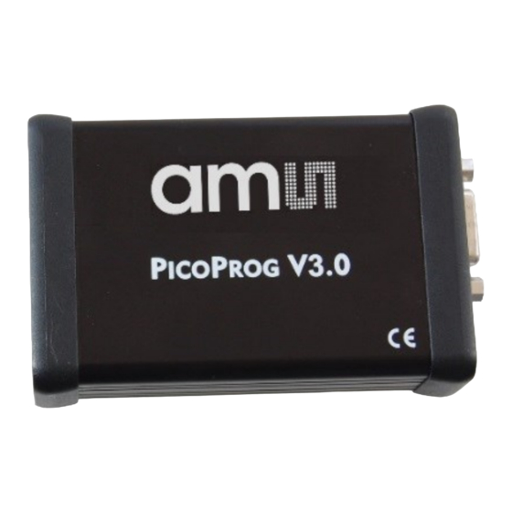
USB cable to the PC. Figure 4: Connect PICOPROG Now install of the ams GP30 evaluation software. For details see chapter 3. If the software and PicoProg driver is already installed then you can skip this section and continue with item 4. - Page 5 Never use configuration files other than for gas meters, as long as the gas meter board is plugged and energized by external voltage. Click on the Write Config button to write the configuration file into the TDC-GP30 chip. Connect the external voltage source (9 to 20 V) and the transducers (spool piece) to the Gasmeter V1.1.
-
Page 6: Installation Of The Software
You may be prompted for a GP30 Evaluation License Code to unlock the software. If so, please send an email request to support.stutensee@ams.com to request an unlock code with validity for one year. Enter the code provided into the dialog box and the software will unlock. - Page 7 TDC-GP30 in gas meters Figure 7: Graphical user’s interface (GUI) of the GP30 evaluation software. Click on System Reset button. The two indicators on the GIU, namely Pico Prog FW Version and Comm. With GP30 OK? should now turn to green. First one indicates that there is communication between the computer and the PicoProg.
-
Page 8: Circuit Design In Detail
TDC-GP30 in gas meters Circuit Design in Detail The circuit design and the layout of the Gasmeter V1.1 can be seen in section 5. Basically, the Gasmeter V1.1 is designed to send ultrasonic fire pulses that have relatively high peak values and amplify the received signal to a value which is meaningful for the GP30. The circuit was designed for development and test purposes, therefore there are many things added to increase the flexibility, observability and immunity against other disturbances. - Page 9 TDC-GP30 in gas meters Figure 9: Send and receive signals 516µs Note: Oscilloscope view of the signals. Yellow: Sent signal (fire pulses), 13Vpp. Purple: Received signal, amplified, ~500mVpp(max). The time of flight between transducers is 516µs for air at room temperature.
-
Page 10: Gpio Signals
TDC-GP30 in gas meters GPIO Signals TDC-GP30 gas meter mode is turned on by setting TI_ERA_EN and TI_GM_MODE. Figure 11: Setting gas meter mode in GUI With this setting, general purpose IOs GPIO0, GPIO1, GPIO4 and GPIO6 provide the signals to control external analog switches. -
Page 11: Hardware
TDC-GP30 in gas meters Hardware Layout ams Application Note Page 11 [v1-01] 2017-Jan-31 Document Feedback... -
Page 12: Schematics
TDC-GP30 in gas meters Schematics ams Application Note Page 12 [v1-01] 2017-Jan-31 Document Feedback... -
Page 13: Contact Information
TDC-GP30 in gas meters Contact Information Buy our products or get free samples online at: www.ams.com/ICdirect Technical Support is available at: www.ams.com/Technical-Support Provide feedback about this document at: www.ams.com/Document-Feedback For further information and requests, e-mail us at: ams_sales@ams.com For sales offices, distributors and representatives, please visit: www.ams.com/contact... -
Page 14: Copyrights & Disclaimer
No obligation or liability to recipient or any third party shall arise or flow out of ams AG rendering of technical or other services. -
Page 15: Revision Information
TDC-GP30 in gas meters Revision Information Changes from previous version 0.1 to current revision 1-01 (2017-Jan-31) Page Transfer to corporate design New section 4.1 9, 10 Note: Page numbers for the previous version may differ from page numbers in the current revision.


Need help?
Do you have a question about the TDC-GP30 and is the answer not in the manual?
Questions and answers