Table of Contents
Advertisement
Power source
Power requirements
Output (IEC60705)
Microwave frequency
Timer
Oven cavity size
Outside dimensions
Inside dimensions
Weight
510mm(W) x 390mm(D) X 305MM (H)
359mm(W) X 352mm(D) x 217mm(H)
Specifications subject to change without notice
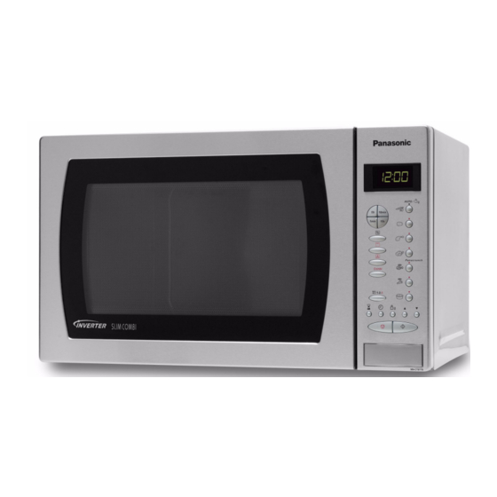
NN-CT577SEPG
230VAC Single Phase 50Hz
Microwave 1260W
Grill 1360
Convection 1380W
Micro / Grill Combi 2390W
Micro / Conv Combi 2400
Microwave 1000W
Grill1300W
Convection 1300W
2450Mhz
99 min 99 second
27L
13Kg
HAD0705010C2
Microwave Oven
Advertisement
Table of Contents
Troubleshooting

Related Manuals for Panasonic NN-CT577SEPG


Summary of Contents for Panasonic NN-CT577SEPG
-
Page 1: Microwave Oven
HAD0705010C2 Microwave Oven NN-CT577SEPG Power source 230VAC Single Phase 50Hz Power requirements Microwave 1260W Grill 1360 Convection 1380W Micro / Grill Combi 2390W Micro / Conv Combi 2400 Output (IEC60705) Microwave 1000W Grill1300W Convection 1300W Microwave frequency 2450Mhz Timer 99 min 99 second... -
Page 2: Table Of Contents
WARNING This service information is designed for experienced repair technicians only and is not designed for use by the general public. It does not contain warnings or cautions to advise non-technical individuals of potential dangers in attempting to service a product. Products powered by electricity must be serviced or repaired only by expe- rienced proffesional technicians. -
Page 3: Feature Chart
2 Feature Chart Function Microwave Grill Convection Combi Sensor Reheat Sensor Cook Sensor Combi Weight Defrost Weight Combination Weight Reheat Weight Cook Auto Preheat Weight Crisp Stage Cooking 1 stage Delay/Stand More / Less Kg / lb- oz Clock 24 h Word prompt None, Italian, Spanish, Dutch, French, German, Greek, Portu-... -
Page 4: Control Panel
3 Control Panel... -
Page 5: Inverter Warnings
4 Inverter Warnings The inverter circuit board supplies the magnetron tube with a very high voltage (4000 volts). Danger • The inverter circuit board operates at high voltages and high temperatures. The Inverter PCB • Operates at a very high voltage and current. •... -
Page 6: Wiring Diagram
6 Wiring Diagram NOTE WHEN REPLACIN ANY COMPONENT S RECONNECT THE WIRE HARNESS ACCORDIN T O THE COLOURS BELOW COL OURS INDICATED INSIDE BRACKETS () INDICATE THE COLOUR O THE CONNECTOR HOUSIN MA NETRON PRIMARY LATCH SWITCH CAUTION HEAT SINK (WH) (YE) (HOT LI E) -
Page 7: Variable Power Cooking Control
7 Description of the Operating Sequence 7.1 Variable power cooking control pad pressed: The output power is controlled by the inverter power 2. The digital programmer circuit determines the supply. The level of output from the inverter circuit is power level and the cooking time and indicates the controlled by a pulse width modulated signal from the operating state in the display. - Page 8 The aluminium heat sink becomes very hot when the during operation and allow time for it to cool down inverter circuit operates. Never touch this heat sink before servicing the microwave oven. figure 4 HV Inverter warning TORS WARNING For about 30 seconds after the oven is turned off, an INVERTER POWER SUPPLY GROUNDING electric charge remains in the high voltage capacitors on the inverter circuit board.
-
Page 9: Part Replacement
4. Short the magnetron input terminal to the micro- wave oven chassis using an insulated handle screw- IMPORTANT NOTICE driver. When the microwave oven is operating the following 5. Always touch the microwave oven chassis and then components carry a potential above 240VAC. the magnetron terminal. -
Page 10: Part Replacement Procedure
9 Part Replacement Procedure 9.1 Magnetron 4. Remove the 1 screw holding the earth wire to the magnetron. 1. Discharge the high voltage capacitors on the 5. Remove the connector CN701 and CN702 from the inverter circuit. inverter PCB.figure 9 2. - Page 11 Replacing the inverter...
-
Page 12: Fan Motor
9.3 Digital Programmer Circuit (DPC) 1. Carefully remove all solder from the terminal pins of and membrane key board. the low voltage transformer / power relays using a NOTE: Ground any static electric from your body before 30W soldering iron and a solder sucker. handling the digital programmer circuit (DPC). -
Page 13: Turntable Motor
After replacing component parts of the door, fol- low the instructions below for proper installation and adjustment of the door, this is to prevent microwave leakage. 1. When mounting the door to the oven, adjust the door parallel to the bottom of the oven face plate by adjusting the upper hinge. -
Page 14: Component Test Procedure
10 Component Test Procedure Caution 3. Check the continuity between each filament termi- nal and the magnetron case, a good magnetron ∞ • The inverter circuit operates at high voltages. indicates infinite resistance. • Never attempt to measure the high voltage on the inverter circuit. - Page 15 figure 17 Inverter circuit board layout 10.6 Inverter power supply unit Warning Do not attempt to make any measurements in the high voltage circuit of the inverter or magnetron. See troubleshooting of the inverter circuit and magne- tron on <$elemtextto determine if the inverter power supply is still functioning.
-
Page 16: Measurements And Adjustments
11 Measurements and Adjustments Warning 4. Stir the water again and read the temperature of the water. (Record as T2). • Only replace parts with parts from the original man- 5. The normal temperature rise at the high power posi- ufacturer. -
Page 17: Troubleshooting Guide
12 Troubleshooting Guide Caution 1. Do not try to repair the H.V. Inverter power supply. Replace the inverter circuit board as a complete unit. 2. Do not adjust the preset volume on the Inverter. It is very dangerous to repair or adjust without special test equiptment, the inverter handles very high voltage and current. - Page 18 12.1 Troubleshooting (no operation) Symptom Cause Correction 1. Oven is dead. 1. Open or loose lead wire harness. Fuse is OK 2. Open low voltage transformer. No display and no operation at all. 3. Defective DPC AU or DPC DU 2.
- Page 19 12.3 roubleshooting (other problems) Symptom Cause Correction 1. Microwave output is low. 1. Decrease in power source volt- Consult electrician. Oven takes a long time to cook food. age. Refer to output test procedures. 2. Open or loose wiring of magne- tron filament circuit causing inter- mittent oscillation.
-
Page 20: Digital Programmer Circuit
12.6 Troubleshooting inverter by microwave oven input current This is an alternative way to test the inverter circuit by monitoring the input current to the microwave oven. The microwave oven must be set in self test mode to activate the self diagnostic failure code system. Alternate way to troubleshoot oven with AC Ampere meter used H95, H97, H98, H99 appears in display window a short time after start key is pressed and no microwave oscillation with AC Ampere meter used for troubleshooting. - Page 21 Power relay (RY2 ) does not IC-1 pin 23 during Abnormal operate operation Normal 5V Create a short circuit RY2 does not turn on RY2 between pin 6 and pin RY2 turns on IC-220 16 of IC-2 No microwave oscillation IC-1 pin 18 and 16 Abnormal IC-1...
Need help?
Do you have a question about the NN-CT577SEPG and is the answer not in the manual?
Questions and answers