Philips FC7070 Service Manual
Vacuum & mopping system aquatrio
Hide thumbs
Also See for FC7070:
- User manual (230 pages) ,
- Quick start manual (6 pages) ,
- User manual (126 pages)
Advertisement
Table of Contents
- 1 Product Information
- 2 Technical Information
- 3 Electrical Diagram
- 4 Disassembly- and Re-Assembly Advise
- 5 Upper / Lower Stick
- 6 Remove the Complete Stick from the Nozzle
- 7 Open the Upper Stick Assy and Lower Stick Assy
- 8 Nozzle
- 9 Parts List
- 10 Exploded View
- Download this manual
See also:
User Manual
Philips Consumer Lifestyle
Service Manual
PRODUCT INFORMATION
• This product meets the requirements regarding
interference suppression on radio and TV.
• After the product has been repaired, it should function
properly and has to meet the safety requirements as
officially laid down at this moment.
• All removable parts are dishwasher proof.
Published by Philips Consumer Lifestyle
12/03
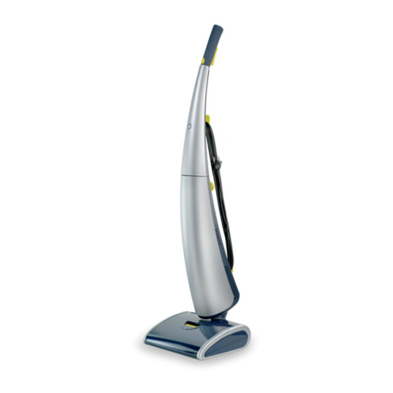
Vacuum & Mopping system AquaTrio
TECHNICAL INFORMATION
• Voltage
• Frequency
• Power Consumption (IEC)
• Colour setting
• Weight
• Dimensions L x W x H (cm)
• Clean Water Tank Capacity
• Dirty Water Tank Capacity
(OPTIONAL) Accessories
• Replacement brushes - FC8054
• Drip tray
Printed in the Netherlands
Appliance on Driptray
© Copyright reserved
FC7070/01
FC7070/11
FC7070/61
FC7070/81
: 220 V / 230 V
: 50 Hz
: 450 W
: Dark midnight &
Lime Yellow
: 7,5 kg
: 117,2 x 38,2 x 36,4
: 0,7 L
: 1,0 L
Subject to modification
Advertisement
Table of Contents

Related Manuals for Philips FC7070


Summary of Contents for Philips FC7070
- Page 1 • Clean Water Tank Capacity : 0,7 L • Dirty Water Tank Capacity : 1,0 L (OPTIONAL) Accessories • Replacement brushes - FC8054 • Drip tray Published by Philips Consumer Lifestyle Printed in the Netherlands © Copyright reserved Subject to modification 12/03...
- Page 2 FC7070/01 /11 /61 /81 Electrical diagram: Dead Man Switch Life Relay SPST Resistive Capaci- (pulsed) Power tive Capacitive Supply Sensor Power Relay Supply CWT PCBA SPST Isolated Pump Brush 230 VAC Power Supply Hall Sensor Inter- connect Back- Main PCBA...
- Page 3 FC7070/01 /11 /61 /81 DISASSEMBLY- AND RE-ASSEMBLY ADVISE Remove the complete stick from the nozzle. Secondly remove the ten screws from the Front Frame and remove the Front Frame from the Lower Stick assy. You can To be able to open the Upper Stick assy and Lower Stick assy now access all internal components.
- Page 4 FC7070/01 /11 /61 /81 DISASSEMBLY- AND RE-ASSEMBLY ADVISE To exchange the PCBA in the Lower Stick assy, open the PCB Nozzle Box and undo connectors J3 (Main PCBA), J4 (Clean Water To be able to open the nozzle, fi rst open the hood, take out sensor) and J5 (DWT Hall sensor).
- Page 5 FC7070/01 /11 /61 /81 PARTS LIST Service code Description Service code Description 4322 005 32941 Dirty water tank lid assy 4322 006 96191 Clean water pump 4322 005 31191 Dirty water tank (excl. lid) 4322 003 38931 Brush cover 4322 009 00611...
- Page 6 FC7070/01 /11 /61 /81 EXPLODED VIEW...
- Page 7 FC7070/01 /11 /61 /81 EXPLODED VIEW...
- Page 8 FC7070/01 /11 /61 /81 EXPLODED VIEW...
- Page 9 FC7070/01 /11 /61 /81 EXPLODED VIEW...
Need help?
Do you have a question about the FC7070 and is the answer not in the manual?
Questions and answers