Table of Contents
Advertisement
Quick Links
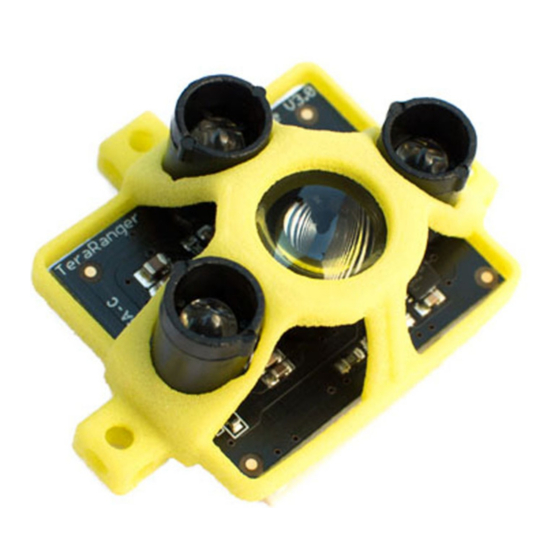
Installation and Operation Manual
Version 1.0.0, June 2016
Firmware 5.0.1
Technical Specifications:
Principle:
Range:
Update rate:
Range resolution:
Accuracy:
Field of view:
Supply voltage:
Supply current:
Interfaces:
Connector:
Designs:
Weight:
Sensor types:
Infrared Time‐of‐Flight (ToF)
Up to 14m indoors (At least 5 to 6m in sunlight)
1000Hz in fast mode (Up to 600Hz in precision mode)
0.5cm
± 4cm in precision mode
3º
10V DC recommended (10 to 20V DC accepted)
50mA average (110mA peak @12V)
1.UART (+5V level, up to 115200,8,N,1)
2.TWI (I2C compatible, +5V level, up to 400kHz, configurable address)
15 pin DF13 (open‐ended, 1.27mm pitch flat ribbon cable provided)
Box, Spider, Frame
8g (Spider, Frame) or 10g (Box)
Type A (Box, Spider) and Type B (Box, Frame)
Advertisement
Table of Contents

Related Manuals for TeraBee TeraRanger One


Summary of Contents for TeraBee TeraRanger One
-
Page 1: Technical Specifications
Installation and Operation Manual Version 1.0.0, June 2016 Firmware 5.0.1 Technical Specifications: Principle: Infrared Time‐of‐Flight (ToF) Range: Up to 14m indoors (At least 5 to 6m in sunlight) Update rate: 1000Hz in fast mode (Up to 600Hz in precision mode) Range resolution: 0.5cm Accuracy:... -
Page 2: Table Of Contents
Copyright © Terabee 2016 Safety Notes The TeraRanger One is eyesafe in all conditions, including system failure. However, please keep a minimum of 20cm distance from your eyes when handling the sensor ... -
Page 3: About The Teraranger One
If you have purchased a USB adapter in addition to your TeraRanger One, you will also receive the following items: ... -
Page 4: Dimensions And Mounting
sources, etc. About the Connector The TeraRanger One connects to your equipment using a 15 pin connector of the Hirose ... -
Page 5: Uart Data Interface
connect the TeraRanger One to a real RS232 port of a PC, the voltage levels are different ... -
Page 6: Usb Interface
allows you to connect up to eight TeraRanger One sensors and read the data from the ... -
Page 7: Connecting The Teraranger One Using A Computer With A Serial Console
Copyright © Terabee 2016 Connecting the TeraRanger One Using a Computer With a Serial Console Your TeraRanger One can interact with any serial console using the following configuration: ... -
Page 8: Macos
Copyright © Terabee 2016 “Type” box. If you want to change the sensor’s measurement mode, type “F” in the type box to select the ... -
Page 9: Linux
Copyright © Terabee 2016 name) The distance data will now appear on the terminal in “Binary” mode and will look like this: Press the commands Shift+T to switch from binary mode to “Text” mode. This will display the distance values in millimeters, as follows: To change the sensor from its fast mode to its precision mode, press: Shift+F for “Fast” mode Shift+P for “Precision” mode Shift+O for “Optimal” mode To stop the data measurement, press: Ctrl+A then K Linux Linux is very similar to MacOS and also works with a terminal. Open a terminal (shortcut: ctrl+alt+t): type: ls /dev/tty* 90 Rue Henri Fabre Website: www.teraranger.com 01630 St. Genis‐Pouilly Technical support: support@teraranger.com... -
Page 10: Running The Teraranger One In Ros
h ttp://www.ros.org ) node which provides a topic to access the TeraRanger One data stream. Please note that the s ensor has to be ... -
Page 11: Protocol Description
one. Protocol description The TeraRanger One can be read out and controlled via either UART or I2C. Even though ... - Page 12 TeraRanger One is unable to measure a distance, it will output 1\r\n as an ...
-
Page 13: I2C Interface
are kept in volatile memory by the sensor and have to be set after each power cycle. I2C interface An alternative way to read out the TeraRanger One is via its TWI bus (also known as I2C). ... -
Page 14: How To Connect To Pixhawk Autopilot
Copyright © Terabee 2016 Reading the distance is done by sending 0x61 (this is the 7 bit address 0x30 followed by the read bit '1') followed by three byte read operations. The first two bytes you receive are a 16 bit word containing the latest measurement in mm, the third byte is the CRC8 checksum. Writing commands to the TeraRanger One: 1. Send the address byte consisting of a 7 bit base address and the last bit indicating write (‘0’), e.g. 0x60 for base address 0x30. All commands listed in the table below are write operations, the answer will be in the next read operation for which you have to send the 7 bit address with the read bit set. 2. Send the desired command listed in the table below. 3. In case the command creates an answer, read it back immediately. Reading data from the TeraRanger One: 1. Send the address byte consisting of 7 bit base address and the last bit indicating read (‘1’), e.g. 0x61 for base address 0x30. 2. Read back the the number of bytes imposed by the command, e.g. three bytes for a distance reading. Command in Command name Command explanation hexadecimal 0x01 WHO_AM_I Write this value to TROne via I2C and the next distance reading will contain 0xA1 in the first byte (ignore others). You can use this function to uniquely identify a TeraRanger One on the I2C bus. 0xA2 CHANGE_BASE_ADDR ... -
Page 15: How To Calculate The Crc8 Checksum
Copyright © Terabee 2016 In its default state, the TeraRanger One can be connected to the Pixhawk autopilot using the TeraRanger I2C adapter. Currently, Ardupilot firmware from 3.3.3 supports the TeraRanger One as a precision altimeter. You can find details on how to connect the TeraRanger One to your Pixhawk on h ttp://ardupilot.org/copter/docs/commonterarangeronerangefinder.html . Important: When the Pixhawk boots, the TeraRanger One needs to already be powered on, or at least be powered on at the same time as the Pixhawk. If you power the TeraRanger One after the Pixhawk has booted, it will not be recognised! How to calculate the CRC8 checksum All data telegrams in UART binary and I2C output are ending with a CRC8 checksum of the previous bytes including the header byte ‘T’. Please find below an example function you can use to calculate this checksum from the received bytes which you can then compare to the received checksum to figure out if transmission errors occurred. u i n t 8 _ t c r c 8 ( ... -
Page 16: Understanding The Field Of View
Copyright © Terabee 2016 0 x 4 e , 0 x 4 9 , 0 x 4 0 , 0 x 4 7 , 0 x 5 2 , 0 x 5 5 , 0 x 5 c , 0 x 5 b , 0 x 7 6 , 0 x 7 1 , 0 x 7 8 , 0 x 7 f , ... - Page 17 Copyright © Terabee 2016 90 Rue Henri Fabre Website: www.teraranger.com 01630 St. Genis‐Pouilly Technical support: support@teraranger.com France (next to CERN) Commercial: teraranger@terabee.com 17 ...
Need help?
Do you have a question about the TeraRanger One and is the answer not in the manual?
Questions and answers