Advertisement
Table of Contents
- 1 Table of Contents
- 2 Warning Decal Placement
- 3 Important Precautions
- 4 Before You Begin
- 5 Part Identification Chart
- 6 Assembly
- 7 How to Use the Treadmill
- 8 How to Fold and Move the Treadmill
- 9 Maintenance and Troubleshooting
- 10 Exercise Guidelines
- 11 Part List
- 12 Exploded Drawing
- 13 Ordering Replacement Parts
- 14 Recycling Information
- Download this manual
Model No. PETL80715.0
Serial No.
Write the serial number in the space
above for reference.
Serial
Number
Decal
CUSTOMER SERVICE
UNITED KINGDOM
Call: 08457 089 009
From Ireland: 053 92 36102
Website: www.iconsupport.eu
E-mail: csuk@iconeurope.com
Write:
ICON Health & Fitness, Ltd.
c/o HI Group PLC
Express Way
CASTLEFORD
WF10 5QJ
UNITED KINGDOM
AUSTRALIA
Call: 1800 993 770
E-mail: australiacc@iconfitness.com
Write:
ICON Health & Fitness
PO Box 635
WINSTON HILLS NSW 2153
AUSTRALIA
CAUTION
Read all precautions and instruc-
tions in this manual before using
this equipment. Save this manual
for future reference.
USER'S MANUAL
www.iconeurope.com
Advertisement
Table of Contents

Related Manuals for Pro-Form Endurance M8i


Summary of Contents for Pro-Form Endurance M8i
- Page 1 Model No. PETL80715.0 Serial No. USER’S MANUAL Write the serial number in the space above for reference. Serial Number Decal CUSTOMER SERVICE UNITED KINGDOM Call: 08457 089 009 From Ireland: 053 92 36102 Website: www.iconsupport.eu E-mail: csuk@iconeurope.com Write: ICON Health & Fitness, Ltd. c/o HI Group PLC Express Way CASTLEFORD...
-
Page 2: Table Of Contents
TABLE OF CONTENTS WARNING DECAL PLACEMENT ............. . .2 IMPORTANT PRECAUTIONS . -
Page 3: Important Precautions
IMPORTANT PRECAUTIONS WARNING: To reduce the risk of burns, fire, electric shock, or injury to persons, read all important precautions and instructions in this manual and all warnings on your treadmill before using your treadmill. ICON assumes no responsibility for personal injury or property damage sus- tained by or through the use of this product. - Page 4 22. Never leave the treadmill unattended while it 26. Never insert any object into any opening on is running. Always remove the key, press the the treadmill. power switch into the off position (see the drawing on page 5 for the location of the 27.
-
Page 5: Before You Begin
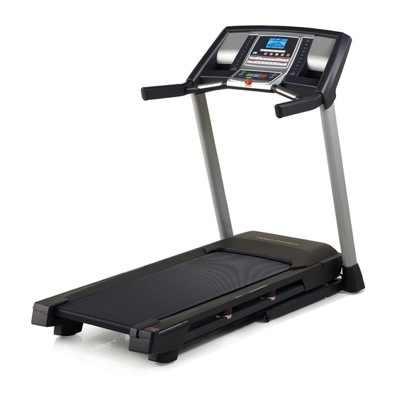
Thank you for selecting the new PROFORM reading this manual, please see the front cover of this ® ENDURANCE M8I treadmill. The ENDURANCE M8I manual. To help us assist you, note the product model treadmill provides an impressive selection of features number and serial number before contacting us. -
Page 6: Part Identification Chart
PART IDENTIFICATION CHART Use the drawings below to identify small parts used for assembly. The number in parentheses below each draw- ing is the key number of the part, from the PART LIST near the end of this manual. The number following the key number is the quantity used for assembly. -
Page 7: Assembly
ASSEMBLY • Assembly requires two persons. • Left parts are marked “L” or “Left” and right parts are marked “R” or “Right.” • Place all parts in a cleared area and remove the packing materials. Do not dispose of the packing •... - Page 8 2. Make sure that the power cord is unplugged. Press a Base Cap (74) into each side of the Base (85). Identify the Right Upright (90). Have a second person hold the Right Upright near the Base (85). See the inset drawing. Tie the wire tie (A) in the Right Upright (90) securely around the end of the Upright Wire (81).
- Page 9 4. Hold the Right Upright (90) against the Base (85). Be careful not to pinch the wires. Partially tighten three 3/8" x 4" Screws (7) with three 3/8" Star Washers (13) into the Right Upright and the Base; do not fully tighten the Screws yet.
- Page 10 6. Identify the Right Handrail (100). Remove the tie from the 5/16" Cage Nut (92). If necessary, press the Cage Nut back into place. Hole Hold the Right Handrail (100) near the Right Upright (90). Insert the Upright Wire (81) through the bracket on the bottom of the Left Handrail.
- Page 11 8. Identify the Right Handrail Tube (102). Insert the Right Handrail Tube (102) into the top of the Right Handrail (100). Attach the Right Handrail Tube with two 1/4" x 1" Screws (28); start both Screws, and then tighten them. Then, insert a Handrail Insert (31) into the top of the Right Handrail.
- Page 12 10. Insert the Upright Wire (81) into the Right Upright (90) as you set the console assembly on the Left and Right Handrails (99, 100). Make sure that Console Assembly no wires are pinched. Attach the console assembly with two 5/16" x 1" Screws (35) and two 5/16"...
- Page 13 12. Identify the Right and Left Trays (27, 36). Make sure that the indicated notch on each Tray is positioned as shown. Attach the Trays with eight #8 x 3/4" Screws (4); start all eight Screws, and then tighten them. Do not overtighten the Screws.
- Page 14 14. Remove the 5/16" Nut (34) and the 5/16" x 1 3/4" Bolt (23) from the bracket on the Base (85). Next, orient the Storage Latch (96) as shown. Attach the lower end of the Storage Latch (96) to the bracket on the Base (85) with the 5/16" x 1 3/4"...
- Page 15 16. Firmly tighten all six 3/8" x 4" Screws (7). Then, slide the Left and Right Base Covers (82, 83) downward. 17. Make sure that all parts are properly tightened before you use the treadmill. If there are sheets of plastic on the treadmill decals, remove the plastic.
-
Page 16: How To Use The Treadmill
HOW TO USE THE TREADMILL HOW TO PLUG IN THE POWER CORD Follow the steps below to plug in the power cord. This product must be earthed. If it should malfunc- 1. Plug the indicated end of the power cord into the tion or break down, earthing provides a path of least socket on the treadmill. - Page 17 CONSOLE DIAGRAM FEATURES OF THE CONSOLE You can even listen to your favorite workout music or audio books with the console’s sound system. The treadmill console offers an impressive array of features designed to make your workouts more effec- To turn on the power, see page 18. To use the manual mode, see page 18.
- Page 18 HOW TO TURN ON THE POWER HOW TO USE THE MANUAL MODE IMPORTANT: If the treadmill has been exposed to 1. Insert the key into the console. cold temperatures, allow it to warm to room tem- perature before you turn on the power. If you do See HOW TO TURN ON THE POWER at the left.
- Page 19 4. Change the incline of the treadmill as desired. The My Trail tab will show a track that represents 400 m (1/4 mile). As you exercise, the flashing To change the incline of the treadmill, press the rectangle will show your progress. The My Trail tab Incline increase or decrease button or one of the will also show the number of laps you complete.
- Page 20 6. Measure your heart rate if desired. 7. When you are finished exercising, remove the key from the console. You can measure your heart rate using either the handgrip heart rate monitor or an optional Step onto the foot rails, press the Stop button, and chest heart rate monitor (see page 23 for infor- adjust the incline of the treadmill to the lowest mation about the optional chest heart rate...
- Page 21 HOW TO USE A WEIGHT-LOSS WORKOUT Each workout is divided into one-minute segments. One speed setting and one incline setting are 1. Insert the key into the console. programmed for each segment. Note: The same speed setting and/or incline setting may be pro- See HOW TO TURN ON THE POWER on page 18.
- Page 22 HOW TO USE AN IFIT WORKOUT To re-run a recent iFit workout from your sched- ule, first press the Track button. Next, press the Note: To use an iFit workout, you must have an increase and decrease buttons to select the optional iFit module.
- Page 23 6. Follow your progress with the displays. HOW TO USE THE SOUND SYSTEM See step 5 on page 19. To play music or audio books through the console sound system while you exercise, plug a 3.5 mm male The My Trail tab will show a map of the trail you to 3.5 mm male audio cable (not included) into the jack are walking or running or it will show a track and on the console and into a jack on your MP3 player,...
- Page 24 THE SETTINGS MODE CONTRAST LVL—Press the Incline increase and decrease buttons to adjust the contrast level of the The console features an information mode that keeps display. track of treadmill information and allows you to person- alize console settings. If a module is connected, you may also select the following screens: 1.
-
Page 25: How To Fold And Move The Treadmill
HOW TO FOLD AND MOVE THE TREADMILL HOW TO FOLD THE TREADMILL HOW TO MOVE THE TREADMILL To avoid damaging the treadmill, adjust the incline Before moving the treadmill, fold it as described at the to zero before you fold the treadmill. Then, remove left. -
Page 26: Maintenance And Troubleshooting
MAINTENANCE AND TROUBLESHOOTING MAINTENANCE SYMPTOM: The power turns off during use Regularly clean the treadmill and keep the walking a. Check the power switch (see drawing c at the left). belt clean and dry. First, press the power switch into If the switch has tripped, wait for five minutes and the off position and unplug the power cord. - Page 27 Next, locate the Reed Switch (52) and the Magnet b. If the walking belt is overtightened, treadmill per- (50) on the left side of the Pulley (49). Turn the formance may decrease and the walking belt may Pulley until the Magnet is aligned with the Reed become damaged.
- Page 28 SYMPTOM: The walking belt is off-center SYMPTOM: The walking belt slips when walked on IMPORTANT: The walking belt should be centered a. First, remove the key and UNPLUG THE POWER between the foot rails. If the walking belt rubs CORD. Using the hex key, turn both idler roller against the foot rails, the walking belt may become screws clockwise, 1/4 of a turn.
-
Page 29: Exercise Guidelines
EXERCISE GUIDELINES Burning Fat—To burn fat effectively, you must exer- WARNING: cise at a low intensity level for a sustained period of Before beginning this time. During the first few minutes of exercise, your or any exercise program, consult your physi- body uses carbohydrate calories for energy. -
Page 30: Part List
PART LIST Model No. PETL80715.0 R0115A Key No. Qty. Description Key No. Qty. Description #8 x 1/2" Silver Screw Reed Switch Clip #3 x 1/4" Screw Reed Switch Base Pad 1/4" x 1 1/4" Screw #8 x 3/4" Screw Drive Motor Pulse Crossbar Motor Belt Filter... - Page 31 Key No. Qty. Description Key No. Qty. Description Left Handrail Tube Left Speaker Cover Right Handrail Tube Right Speaker Cover Speaker Left Speaker Back Right Speaker Back – User’s Manual Base Pad Spacer Note: Specifications are subject to change without notice. For information about ordering replacement parts, see the back cover of this manual.
-
Page 32: Exploded Drawing
EXPLODED DRAWING A Model No. PETL80715.0 R0115A... - Page 33 EXPLODED DRAWING B Model No. PETL80715.0 R0115A...
- Page 34 EXPLODED DRAWING C Model No. PETL80715.0 R0115A...
- Page 35 EXPLODED DRAWING D Model No. PETL80715.0 R0115A...
-
Page 36: Ordering Replacement Parts
ORDERING REPLACEMENT PARTS To order replacement parts, please see the front cover of this manual. To help us assist you, be prepared to provide the following information when contacting us: • the model number and serial number of the product (see the front cover of this manual) •...
Need help?
Do you have a question about the Endurance M8i and is the answer not in the manual?
Questions and answers
How to get hex let?
@Getahun Mare ”Hex Key”
The hex keys are included with the Pro-Form Endurance M8i treadmill. You do not need to purchase them separately.
This answer is automatically generated