
Related Manuals for Optika B-383LD1


Summary of Contents for Optika B-383LD1
- Page 1 B-380 Series INSTRUCTION MANUAL Model B-383LD1 B-383LD2 Version: Issued: 18, 03, 2015...
-
Page 2: Table Of Contents
Table of Contents Warning Symbols and conventions Safety Information Intended use Package Contents Unpacking Product specifications Overview Using the microscope Using the fluorescence Maintenance Troubleshooting User replaceable accessories and spare parts Equipment disposal Page 2... -
Page 3: Symbols And Conventions
Warning This microscope is a scientific precision instrument designed to last for many years with a minimum of mainte- nance. It is built to high optical and mechanical standards and to withstand daily use. We remind you that this manual contains important information on safety and maintenance, and that it must therefore be made accessible to the instrument users. -
Page 4: Unpacking
Place the observation head onto the top of the arm and tighten the lock-screw. Insert the eyepieces into the eye tubes and fix them with the tiny screws on the side of the eye tubes. Remove the plastic protection film from the microscope stage. Product specifications B-383LD1 Head: Trinocular, 30° inclined, 360° rotating. Interpupillary adjustment 48-75 mm. Eyepieces: WF10X/20mm. -
Page 5: Overview
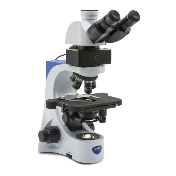
Overview PHOTO/VIDEO PORT DIOPTRIC ADJUSTMENT RING EYEPIECE HEAD LOCKING SCREW REVOLVING NOSEPIECE OBJECTIVE STAGE IRIS DIAPHRAGM TRANSLATION KNOBS CONDENSER CONDENSER CENTERING BRIGHTNESS SCREWS ADJUSTMENT (LEFT SIDE) LED ILLUMINATOR Page 5... - Page 6 INTERPUPILLARY DISTANCE SLIDE CLAMP CONDENSER HEIGHT ADJUSTMENT FINE FOCUSING KNOB COARSE FOCUSING KNOB TENSION ADJUSTMENT KNOB FOCUS STOP KNOB Page 6...
-
Page 7: Using The Microscope
Using the microscope Adjust the observation head Loosen the lock-screw, turn the observation head to a comfortable position for observation, and then lock the lock-screw. Place the specimen on the stage Lock the specimen slide on the mechanical stage using the slide clamp. Ensure that the specimen is centred over the stage opening by adjusting the coaxial knobs of the stage LED lamp settings –... - Page 8 HEAD LOCK SCREW LED ILLUMINATOR ILLUMINATOR LOCK SCREW FILTER SELECTOR (1) Page 8...
-
Page 9: Using The Fluorescence
Using the fluorescence Assembling the epi-fluorescence attachment Take the attachment out of its packaging and put it onto the microscope stand, then tighten the attachment lock- ing screw. Place the optical head onto the top of the attachment and tighten the optical head locking screw. Connect the cable from the epi-fluorescence attachment to the output jack on the rear of the microscope. -
Page 10: Maintenance
Do not disassemble objectives or eyepieces in attempt to clean them. For the best results, use the OPTIKA cleaning kit (see catalogue). If you need to send the microscope to Optika for maintenance, please use the original packaging. Page 10... -
Page 11: Troubleshooting
Troubleshooting Review the information in the table below to troubleshoot operating problems. PROBLEM CAUSE SOLUTION LIGHT DOESN’T TURN ON Power supply not connected Check that the 6Vdc power supply jack is well inserted on the rear of the micro- scope Rotate the brightness adjustment control and check if there is an increase in the light output... -
Page 12: Equipment Disposal
Equipment disposal Art.13 Dlsg 25 july 2005 N°151. “According to directives 2002/95/EC, 2002/96/EC and 2003/108/EC relating to the reduction in the use of hazardous substances in electrical and electronic equipment and waste disposal.” The basket symbol on equipment or on its box indicates that the product at the end of its useful life should be collected separately from other waste. - Page 13 Serie B-380 MANUALE D’ISTRUZIONI Modello B-383LD1 B-383LD2 Versione: 2 Emesso il: 18, 03, 2015...
- Page 14 Indice Contenuti Avvertenza Simboli Informazioni sulla sicurezza Utilizzo previsto Contenuto della confezione Apertura della confezione Specifiche tecniche Descrizione dello strumento Istruzioni per l’uso Utilizzo della fluorescenza Manutenzione Soluzioni per eventuali problemi Accessori sostituibili e parti di ricambio Smaltimento Pagina 14...
- Page 15 Avvertenza Questo microscopio è uno strumento scientifico di alta precisione, progettato per durare a lungo con una mini- ma manutenzione; la realizzazione è secondo i migliori standard ottici e meccanici, per poter essere utilizzato quotidianamente. Vi ricordiamo che questo manuale contiene informazioni importanti per la sicurezza e per la manutenzione dello strumento, e deve quindi essere messo a disposizione di coloro che lo utilizzeranno.
- Page 16 Posizionare la testata d’osservazione nella parte superiore del braccio e stringere la vite di serraggio. Inserire gli oculari nei tubi oculari. Collegare il cavo per l’alimentazione inserendo il connettore nell’apposita presa posta nella parte posteriore del microscopio. Specifiche tecniche B-383LD1 Testata: Ttrinoculare, inclinata 30°, ruotabile 360°. Distanza interpupillare regolabile 48-75mm.. Oculari: WF10X/20mm.
- Page 17 Descrizione dello strumento USCITA FOTO/VIDEO ANELLO DI REGOLAZIONE DIOTTRICA OCULARI VITE SERRAGGIO TESTA REVOLVER PORTAOBIETTIVI OBIETTIVI TAVOLINO TRASLATORE MANOPOLE REGOLAZIONE DIAFRAMMA A IRIDE SPOSTAMENTO TAVOLO CONDENSATORE VITI DI CENTRAGGIO CONDENSATORE REGOLAZIONE LUMINOSITÀ (LATO SINISTRO) ILLUMINATORE A LED Pagina 17...
- Page 18 DISTANZA INTERPUPILLARE PINZA PORTAPREPARATI REGOLAZIONE ALTEZZA DEL CONDENSATORE COMANDO FUOCO MICROMETRICO COMANDO FUOCO MACROMETRICO REGOLAZIONE DELLA TENSIONE LEVA DI BLOCCO FOCUS Pagina 18...
- Page 19 Istruzioni per l’uso Regolazione della testata di osservazione Allentare la vite di serraggio, ruotare la testata fino a trovare una posizione comoda per l’osservazione e quindi avvitarla nuovamente. Posizionamento del vetrino sul tavolo portapreparati Fissare il vetrino con preparato al piano meccanico mediante l’apposita pinzetta per il sostegno dei campioni. Regolando le manopole coassiali del piano portaoggetti, assicurarsi che il vetrino si trovi al centro del campo di osservazione.
- Page 20 VITE FISSAGGIO TESTA ILLUMINATORE LED VITE FISSAGGIO ILLUMINATORE SELETTORE FILTRI (1) Pagina 20...
- Page 21 Utilizzo della fluorescenza Montaggio dell’illuminatore per epi-fluorescenza Estrarre dall’apposito imballaggio l’illuminatore e posizionarlo sulla sommità dello stativo del microscopio avvi- tando la vite di serraggio. Posizionare quindi la testata ottica sopra l’attacco fissandola con l’apposita vite. Collegare il cavo proveniente dall’illuminatore per epi-fluorescenza nel connettore di uscita posto nella parte posteriore del microscopio.
- Page 22 Non smontare gli obiettivi o gli oculari per cercare di pulirli. Per un migliore risultato, utilizzare il kit di pulizia OPTIKA (vedi catalogo). Se si necessita di spedire il microscopio al produttore per la manutenzione, si prega di utilizzare l’imballo originale.
- Page 23 Soluzioni per eventuali problemi Consultare le informazioni riportate nella tabella sottostante per risolvere eventuali problemi operativi. PROBLEMA CAUSA SOLUZIONE L’ILLUMINATORE NON SI Cavo dell’alimentazione Controllare che il cavo jack dell’alimentazione ACCENDE non inserito. 6Vdc sia correttamente inserito nella parte po- steriore del microscopio.
- Page 24 Smaltimento Ai sensi dell’articolo 13 del decreto legislativo 25 luglio 2005 n°151. “Attuazione delle direttive 2002/95/CE, 2002/96/CE e 2003/108/CE, relative alla riduzione dell’uso di sostanze pericolose nelle apparecchiature elettriche ed elettroniche, nonché allo smaltimento dei rifiuti”. Il simbolo del cassonetto riportato sulla apparecchiatura o sulla sua confezione indica che il prodotto alla fine della propria vita utile deve essere raccolto separatamente degli altri rifiuti.
- Page 25 Series B-380 MANUAL DE INSTRUCCIONES Modelo B-383LD1 B-383LD2 Versión: Publicado: 18, 03, 2015...
- Page 26 Cuadro de contenidos Advertencia Símbolos Información de seguridad Utilización Contenido del embalaje Desembalaje Especificaciones técnicas Vista general Funcionamiento Usando la fluorescencia Mantenimiento Solucionar problemas Eliminación de residuos Página 26...
- Page 27 Advertencia Este microscopio es un instrumento científico de precisión. Su utilización está pensada para una larga duración con un mínimo nivel de mantenimiento. Para su fabricación se han utilizado elementos ópticos y mecánicos de elevada calidad que lo convierten en el instrumento ideal para la utilización diaria en las aulas y el laboratorio. Informamos que esta guía contiene importantes informaciones sobre la seguridad y el mantenimiento del pro- ducto y por lo tanto debe ser accesible a todos aquellos que utilizan dicho instrumento.
- Page 28 Inserte los oculares dentro de cada uno de los tubos porta-oculares y fijarlos con el tornillo de sujeción que en- contrará en ambos tubos. Quitar el film de plástico protector de la platina. Especificaciones técnicas B-383LD1 Cabezal: Trinocular, inclinado 30º, giratorio 360º. Ajuste dióptrico.
- Page 29 Vista general SALIDA PHOTO / VIDEO ANILLO DE AJUSTE DE DIOPTRÍAS OCULARES TORNILLO DE BLOQUEO DEL CABEZAL REVÓLVER PORTAOBJETIVOS OBJETIVOS PLATINA PORTAPREPARADOS MANDOS COAXIALES DE DESPLAZAMIENTO DE LA DIAFRAGMA IRIS PLATINA CONDENSADOR TORNILLOS DE CENTRADO DEL CONDENSADOR AJUSTE BRILLO (A LA IZQUIERDA) ILUMINADOR LED Página 29...
- Page 30 DISTANCIA INTERPUPILAR PINZA DE SUJECIÓN DE MUESTRAS MANDO DE REGULACIÓN DE LA ALTURA DEL CON- DENSADOR MANDO DE ENFOQUE MICROMÉTRICO MANDO DE ENFOQUE MACROMÉTRICO REGULACIÓN DE LA TENSIÓN BLOQUEO DEL MANDO DE ENFOQUE Página 30...
- Page 31 Funcionamiento Regulación del cabezal de observación Aflojar los tornillos de ajuste para girar el cabezal hasta obtener una posición cómoda para la observación antes de fijarla nuevamente. Colocación de la muestra en la platina porta-preparados Fijar la muestra en la platina utilizando las correspondientes pinzas de sujeción de muestras. Regular con los mandos coaxiales situados a un lado del carro mecánico, asegurándose que la muestra se sitúa en el centro del campo de observación.
- Page 32 TORNILLO DE SUJECIÓN DEL CABEZAL ILUMINADOR LED TORNILLO DE SUJECIÓN DEL MÓDULO DE FLUORESCENCIA SELECTOR DE FILTRO EPIFLUORESCENCIA (1) Página 32...
- Page 33 Usando la fluorescencia Montaje de la epi-fluorescencia Extraiga el equipo de epi-fluorescencia de su embalaje y colóquelo sobre el estativo del microscopio, a conti- nuación, apriete el tornillo de bloqueo (sujeción). Coloque el cabezal óptico en la parte superior de la epi-fluorescencia y sujétela con el tornillo de bloqueo. Co- necte el cable de iluminación del accesorio de epi-fluorescencia a la parte posterior del microscopio.
- Page 34 No desmontar los objetivos o los oculares para intentar limpiarlos. Para obtener mejores resultados, utilice el kit de limpieza OPTIKA (véase el catálogo). Si fuera necesario, enviar el microscopio a la empresa Optika para su mantenimiento se ruega utilizar el embalaje original.
- Page 35 Solucionar problemas Revise la información que aparece en la siguiente tabla. PROBLEMA CAUSA SOLUCIÓN LUZ NO SE ENCIENDE Transformador no enchufado Comprobar que el jack del transformador 6Vdc está insertado en la parte trasera del microscopio. Potenciometro Girar el mando de intensidad de luz para incrementar la luz.
- Page 36 Eliminación de residuos En conformidad con el Art. 13 del D.L. de 25 julio 2005 n°151. Actuación de las Directivas 2002/95/CE, 2002/96/ CE y 2003/108/CE, relativas a la reducción del uso de sustancias peligrosas en la instrumentación eléctrica y electrónica y a la eliminación de residuos. El símbolo del contenedor que se muestra en la instrumentación o en su embalaje indica que el producto cuando alcanzará...
- Page 37 Serie B-380 MANUEL D’UTILISATION Modèle B-383LD1 B-383LD2 Version: 18, 03, 2015...
- Page 38 Contenu Avertissement Symboles Précautions Usage Contenu de l’emballage Déballage Caractéristiques techniques Description Utilisation du microscope Réparation et entretien Résolution de problèmes Accessoires et pièces de rechanges Ramassage Page 38...
-
Page 39: Symboles
Avertissement Le présent microscope est un appareil scientifique de précision créé pour offrir une durrée de vie de plusieurs années avec un niveau d’entretien mininum. Les meilleurs composants optiques et mécaniques ont été utilisés pour sa conception ce qui fond de lui un appareil idéal pour une utilisation journalière. Ce guide contient des informations importantes sur la sécurité... -
Page 40: Déballage
Placer la tête de l’observation dans la partie supérieure du bras et serrer la vis de serrage. Introduisez les ocu- laires dans les tubes porte oculaires. Connecter le câble pour l’alimentation en insérant le connecteur dans la prise à l’arrière du microscope. Caractéristiques techniques B-383LD1 Tête: Trinoculaire, inclinée à 30°, rotative sur 360°. Distance interpupillaire réglable 48-75 mm. Oculaires: WF10X/20mm. -
Page 41: Description
Description SORTIE PHOTO VIDÉO RÉGLAGE DE LA DISTANCE INTER PUPILLAIRE OCULAIRES VIS DE FIXATION DE LA TÊTE RÉVOLVER OBJECTIFS SURPLATINE MÉCANIQUE DIAPHRAGME À IRIS COMMANDES COAXIALES CONDENSEUR VIS DE RÉGLAGE DE CONDENSEUR AJUSTEMENT LUMINOSITE (CÔTÉ GAUCHE) ECLAIRAGE LED Page 41... - Page 42 RÉGLAGE DE LA DISTANCE INTER PUPILLAIRE PINCE POUR MAINTENIR LES PRÉPARATIONS RÉGLAGE DE LA HAUTEUR DU CONDENSEUR COMMANDE DE MISE AU POINT MICROMÉTRIQUE COMMANDE DE MISE AU POINT COMMANDE DE MACROMÉTRIQUE RÉGLAGE DE TENSION VERROUILLAGE DU FOYER Page 42...
-
Page 43: Utilisation Du Microscope
Utilisation du microscope Réglage de la tête d’observation Dévissez légèrement les vis de fixation de façon à faire pivoter la tête jusqu’à obtenir une position confortable pour l’observation avant de revisser à nouveau. Positionnement de la préparation sur la platine mécanique Fixez la préparation à... - Page 44 VIS DE BLOCAGE DE LA TÊTE ÉCLAIRAGE LED VIS DE BLOCAGE DE L’ÉCLAIRAGE SÉLECTEUR DE FILTRE Page 44...
- Page 45 Utilisation de la fluorescence Montage de la lampe à épi-fluorescence Extraire l’éclairage de son emballage et placez le sur le statif du microscope, puis serrez la vis de blocage de l’éclairage. Placez la tête optique au dessus de l’éclairage et serrer la vis de blocage de la tête optique. Bran- chez le câble de l’éclairage à...
-
Page 46: Réparation Et Entretien
• Les empreintes digitales peuvent endommager les parties optiques. Pour les meilleurs résultats, utiliser le kit de nettoyage OPTIKA (voir le catalogue). Conserver l’emballage d’origine dans le cas où il serait nécessaire de retourner le microscope au fournisseur pour un entretien ou une réparation. -
Page 47: Résolution De Problèmes
Résolution de problèmes Reportez-vous à l’information dans le tableau ci-dessous pour résoudre les problèmes opérationnels. PROBLÈME CAUSE SOLUTION L’ÉCLAIRAGE NE L’alimentation n’est pas Vérifiez l’alimentation 6Vdc soit bien S’ALLUME PAS branché inséré à l’arrière du microscope. Potentiomètre Tourner le potentiomètre de réglage de la luminosité... -
Page 48: Ramassage
Ramassage Conformément à l’Article 13 du D.L du 25 Juillet 2005 nº151 Action des Directives 2002/95/CE, 2002/96/CE et 2003/108/CE, relatives à la réduction de l’utilisation de substances dangereuses dans l’appareil électrique et électronique et à l’élimination des résidus. Le Symbole du conteneur qui figure sur l’appareil électrique ou sur son emballage indique que le produit devra être, à... - Page 49 Serie B-380 BEDIENUNGSANLEITUNG Model B-383LD1 B-383LD2 Version: Datum: 18, 03, 2015...
- Page 50 Inhalt Warnung Zeichen Sicherheitshinweise Verwendungsempfehlungen Verpackung Öffnung der verpackung Technische Daten Überblick Verwendung des Mikroskops Verwendung der Fluoreszenz Wartung Störungssuche Zubehörteilen Wiederverwertung Pagina 50...
- Page 51 Warnung Dieses Mikroskop ist ein wissenschaftliches Präzisionsgerät, es wurde entwickelt für eine jahrelange Verwen- dung bei einer minimalen Wartung. Dieses Gerät wurde nach den höchsten optischen und mechanischen Standards und zum täglichen Gebrauch hergestellt. Diese Bedienungsanleitung enthält wichtige Informationen zur korrekten und sicheren Benutzung des Geräts. Diese Anleitung soll allen Benutzern zur Verfügung stehen. Wir lehnen jede Verantwortung für eine fehlerhafte, in dieser Bedienungsanleitung nicht gezeigten Verwen- dung Ihrer Produkte ab.
- Page 52 Setzen Sie die Okulare in die Tuben ein. Verbinden Sie das Netzkabel an die Stromversorgung und den Stecker in die Steckdose auf der Rückseite des Mikroskops. Technische Daten B-383LD1 Kopf: Trinokular, 30° schrägeinblick, 360° drehbar. Verstellbarer Augenabstand 48-75mm. Okulare: WF10X/20mm.
- Page 53 Überblick OUTPUT PHOTO / VIDEO EINSTELLRING DIOPTER OKULARE KOPFBEFESTIGUNGSCHRAUBE REVOLVER OBJEKTIVE KREUZTISCH KNÖPFE IRISBLENDE KREUZTISCHBEWEGUNG KONDENSOR SCHRAUBEN EINSTELLUNG KONDENSOREINSTELLUNG HELLIGKEIT (LINKE SEITE) LED BELEUCHTUNG Pagina 53...
- Page 54 PRÄPARATENKLEMMEN KONDENSOREINSTELLUNG FEINTRIEB GROBTRIEB SPANNUNGSEINSTELLUNG FOKUSSPEICHER Pagina 54...
- Page 55 Verwendung des Mikroskops Verstellung des Beobachtungskopf Lockern Sie die Spannschraube, dann drehen Sie den Kopf, bis eine komfortable Position für die Betrachtung erreicht wird. Die Schraube nochmals festigen. Objektträger auf den Tisch legen Befestigen Sie den Objektträger auf dem Kreuztisch mit Hilfe der dafür vorgesehenen Klemme.Benutzen Sie die koaxialen Knöpfen des Kreuztisches, um den Objektträger in der Mitte des Betrachtungsfelds zu positionieren.
- Page 56 KOPFBEFESTIGUNGSCHRAUBE LED BELEUCHTUNG BELEUCHTUNG - BEFE- STIGUNGSCHRAUBE FILTERSELEKTOR (1) Pagina 56...
- Page 57 Verwendung der Fluoreszenz Montage der Beleuchtung für Epi-Fluoreszenz Ziehen Sie die Beleuchtung aus der Verpackung heraus und stellen Sie sie oben auf dem Stativ des Mikroskops. Schrauben Sie die Befestigungschraube. Stellen Sie den optischen Kopf auf die Einrichtung und befestigen Sie ihn mit der vorgesehenen Schraube.
- Page 58 • Die Objektive oder die Okulare sollen bei der Reinigung nicht abgenommen werden. Für gute Ergebnisse verwenden Sie das OPTIKA Reinigungskit (siehe Katalog). Falls das Mikroskop zurück an uns für Wartung geschickt werden muss, verwenden Sie bitte die ursprüngliche Ver- packung.
- Page 59 Störungssuche PROBLEM URSACHE LÖSUNG KEIN LICHT Netzteil Prüfen Sie dass der 6Vdc Netzteil zum Mikroskjop verbunden ist. Potentiometer Drehen Sie das Potentiometer für Helligkeits- einstellung. KEIN OR DUNKLES BILD Die Irisblende is nicht völlig Öffnen die Irisblende geöffnet. Helligkeit is nicht genug Drehen Sie das Potentiometer für Helligkeits- einstellung.
- Page 60 Wiederverwertung Gemäß dem Artikel 13 vom Dekret Nr. 151 vom 25.07.2005 “Umsetzung der Richtlinien 2002/95/EG, 2002/96/EG und 2003/108/EG in Bezug auf die Verwendung gefährlicher Stoffe in elektrischen und elektronischen Geräten sowie die Abfallentsorgung” Das Symbol vom Müllcontainer erscheint auf dem Gerät oder der Verpackung und weist darauf hin, dass das Produkt Ende des Lebens separat von anderen Abfällen entsorgt werden muss.
- Page 61 Pagina 61...
- Page 64 OPTIKA S.r.l. ® Via Rigla, 30 - 24010 Ponteranica (BG) - ITALIA Tel.: +39 035.571.392 - Fax: +39 035.571.435 info@optikamicroscopes.com - www.optikamicroscopes.com OPTIKA Spain ® spain@optikamicroscopes.com OPTIKA USA ® usa@optikamicroscopes.com OPTIKA China ® china@optikamicroscopes.com OPTIKA Hungary ® hungary@optikamicroscopes.com...
Need help?
Do you have a question about the B-383LD1 and is the answer not in the manual?
Questions and answers