Table of Contents
Advertisement
Quick Links
Advertisement
Table of Contents

Related Manuals for Pco ultraviolet


Summary of Contents for Pco ultraviolet
- Page 1 pco.
- Page 2 The information is subject to change without notice and does not represent a commitment on the part of PCO in the future. PCO hereby authorizes you to copy documents for non – commercial use within your organization only. In...
-
Page 3: Table Of Contents
TABLE OF CONTENTS 1 INTRODUCTION ADVANTAGES OF THE PCO.ULTRAVIOLET 2 SAFETY INSTRUCTIONS SAVE MONEY, REDUCE STRESS, STAY HEALTHY 3 SYSTEM COMPONENTS WHAT'S IN THE BOX 4 INSTALLATION 4.1 CAMERA DRIVER 4.2 CAMWARE 5 QUICK START 5.1 PREPARATION 5.2. START 5.3. YOUR FIRST IMAGE 6 CAMERA CONTROL 6.1 THE CAMERA CONTROL WINDOW... - Page 4 APPENDIX A1 TECHNICAL DATA A2 MECHANICAL DIMENSIONS A3 PINOUT OF RJ11 CONNECTOR A4 EXTERNAL DEVICES A4.1 TRIGGER INTERFACE A4.2 USB 2.0/3.0 FOL EXTENDER A5 IMAGE FILE FORMATS A6 SERVICE AND MAINTENANCE A7 CUSTOMER SERVICE AND TROUBLE SHOOTING ABOUT PCO...
-
Page 5: Introduction
1. INTRODUCTION 1. INTRODUCTION Advantages of the pco.ultraviolet Features This high performance 14 bit CCD camera system has an extraordinary quantum efficiency of up to 40% at a wavelength of 193nm. This sensitivity is true sensor performance, without any additional coating. At the... -
Page 6: Safety Instructions
2. SAFETY INSTRUCTIONS Please read the safety instructions completely. Never operate the camera in humid or dusty environments or in places with high amounts of X-ray radiation. Humidity, dust or X- rays could damage the camera. To avoid the risk of water condensation, protect the camera against extreme changes of ambient temperature. -
Page 7: System Components
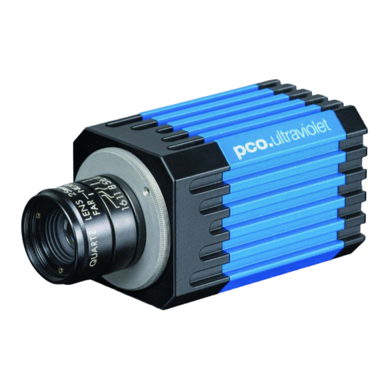
3. SYSTEM COMPONENTS 3. SYSTEM COMPONENTS The camera system includes the following parts. Camera Head C-mount optical connection: The distance between the front edge of the c-mount and the sensor is 17.52 mm. For standard c-mount lenses and adapters. DC Power Jack (connect to power supply) USB 2.0 Connector (connect to PC) -
Page 8: Installation
No].EXE) and follow the instructions of the installation wizard. After finishing the driver installation wizard please connect your pco.ultraviolet camera to its power supply and via enclosed USB 2.0 cable to your computer. The first time the camera is connected via USB to your computer,... -
Page 9: Camware
Install CamWare as Admin to install to program folder, instead it will be installed only to user folder. Then choose install directory. Choose components: Select additional drivers for Camera Link Interface (not available for pco.ultraviolet). After the next two screens installation is complete. -
Page 10: Quick Start
• Camera is connected to the PC • Camera is connected to the power supply and ready 5.2 START Start CamWare and the graphical user interface will start up: NOTE Always install latest CamWare version to be able to use full function of your pco camera. -
Page 11: Your First Image
5. QUICK START 5.3 YOUR FIRST IMAGE Please follow the instructions: • CamWare must be started. • Open view window (b/w or color). • Start live preview. • Apply auto range peak. • You may adjust exposure time, aperture and focus. •... -
Page 12: Camera Control
The camera control window can be opened by selecting the proper command in the Camera Menu or by the corresponding button in the toolbar. The camera control dialog always adapts to the camera type connected. For the pco.ultraviolet camera control settings are spread over four property sheets , which will be explained below. -
Page 13: The Timing Tab
BNC input (see A3, A4). pixelclock intrinsic + trigger acknowledge delay 12 MHz 5.8µs trigger busy exposure read : trigger acknowledge delay : intrinsic delay : readout time : exposure time read External Exp. Ctrl (not available for pco.ultraviolet) -
Page 14: The Sensor (Size) Tab
Timing The exposure time (delay time is not available for pco.ultraviolet) can be adjusted in steps of 1μs. camera type exposure time pco.ultraviolet 1µs … 60s The jitter of the actual exposure start edge: < 14ns. 6.3 THE SENSOR (SIZE) TAB... -
Page 15: The Sensor (Misc.) Tab
(not available for pco.ultraviolet) Double Image / Doubleshutter This feature is widely used for particle image velocimetry (PIV) measurements and is an standard feature of the pco.ultraviolet. The first exposure time t can be any exposure time of the available exp1 range of the pco.ultraviolet camera. - Page 16 The pco.ultraviolet has two conversion factors namely 0.8e 1.4e / count which both can be used in standard and binning mode. As mentioned in 6.3. binning is available for the pco.ultraviolet. The usable extended fullwell-capacity rises in binning mode from 14000 to 24000e .
-
Page 17: The Recording Tab
Acquire Mode Function is not available for pco.ultraviolet. Timestamp A time stamp can be placed into the upper left corner of the image. It can be either off, binary or binary with text. The time resolution is 1μs. -
Page 18: Camware Features
Resolution The drop down list displays the existing image sensor spatial resolutions of all PCO camera systems. Please select the specific resolution and bit depth of the images to be opened. If double shutter images have been recorded and should be opened, Double Shutter Mode should be checked. -
Page 19: Overview
7. CAMWARE FEATURES 7.2 OVERVIEW Menu Bar See chapter 7.3- 7.8 Local Menu Mouse right-click is explained in chapter 7.9 Toolbar Prints the currently displayed image or comment window Opens a b/w | color display window Opens the camera control window (see chapter 6) Opens the convert control (see chapter 7.6) Auto range peak/crop (see chapter 7.6 Convert Control) Live preview (see chapter 5.2) -
Page 20: The File Menu
The image itself will be fitted to the current image size. If the recorder is disabled, the current image sizes will be set to the parameters of the imported image. Open RAW File Set (only for pco.hsfc pro camera) Open RAW Recorder Sequence (image sequence from one camera) This command is used to import a sequence of images. - Page 21 7. CAMWARE FEATURES Export Recorder Sequence (not reloadable!) Use this command to export a sequence of images. If more than one camera is connected and an image window is currently open, the record of the window which has got the input focus will be saved.
- Page 22 Use six digits for filename If you record a sequence of *.b16 files and choose direct record to file CamWare is always using six digits for filename (e.g. t_123456.b16). View Settings Image Browser Here you can select between showing all image files inside the browser window either b/w or color.
- Page 23 7. CAMWARE FEATURES Misc Infotext Use this command to show or hide the start-up information dialog box. Synchronous Scrolling If this item is checked all opened image windows will be scrolled at the same time and in the same manner. View Embedded Image Info (not available) Multi Win Picture Order With the Multi Window you have the ability to view...
-
Page 24: The Camera Menu
For low light conditions only. Close Disconnects camera and switches CamWare to Demo Mode. In case of multiple cameras, all cameras must be closed in order for CamWare to switch to Demo Mode. Rescan Disconnect and reconnect camera. Setup (not available for pco.ultraviolet) -
Page 25: The Acquisition Menu
7. CAMWARE FEATURES 7.5 THE ACQUISITION MENU Live Preview The Live Preview is useful for fast and easy adjusting and focusing of the camera. The active window will be updated. To see another window, simply click on the window. This option is not available in double shutter mode. -
Page 26: The View Menu
7.6 THE VIEW MENU B/W Window Use this command to open a b/w display window. Color Window Use this command to open a color display window. Convert Control BW The user can influence how the 14 bit intensity values (x-axis) of the original image are converted into 8 bit values (y-axis) in different ways. - Page 27 (right mouse button). Skip #images allows for convenient overview at large numbers of images. You can view e.g. every 10 or 50 image only. Multi Window (not available for pco.ultraviolet) Embedded Image Info (not available for pco.ultraviolet)
-
Page 28: The Window Menu
The support files contain relevant hardware information, the log files and the PCO related registry entries. These files are moved into a zip-archive called CWSupport.zip, which can be found in the application... -
Page 29: The Local Menu
7. CAMWARE FEATURES 7.9 THE LOCAL MENU The local menu is opened by clicking the right mouse button inside the client area of an image window. Image Properties Opens an information bubble with main image properties and activates the in-image display. It does not overwrite image data. Camera Control Opens the Camera Control window (see chapter 6). -
Page 30: Additional Features
7.10 ADDITIONAL FEATURES Setting Contrast Area by Mouse You can control the minimum and maximum values used for the conversion from 14 bit to 8 bit with the mouse. Move the mouse cursor into a region which should be shown with maximum contrast. Press the shift and the left mouse button. -
Page 31: Appendix
0 APPENDIX APPENDIX... -
Page 32: A1 Technical Data
A1 TECHNICAL DATA Subject to change, please refer to current data sheet available on our website. -
Page 33: A2 Mechanical Dimensions
C-Mount flange focal distance: 17,52 mm Input Window Filter Attention: The pco.ultraviolet does not have an input window to protect the sensor, if the lens is removed you have direct access to the sensor surface. Therefore, please be very careful when removing or changing optical components. -
Page 34: A3 Pinout Of Rj11 Connector
A3 PINOUT OF RJ11 CONNECTOR Description Trigger in Busy out not used Exposure out +12V (alternative power supply) Pin Position Timing & Signals busy = TRUE: camera is recording or sensor readout in progress busy = FALSE: external trigger is ready to accept exposure = TRUE: exposure of image sensor In Auto Sequence trigger mode the busy signal is always set to... -
Page 35: A4.2 Usb 2.0/3.0 Fol Extender
The Adnaco-SU1 is an optical insulator and also gives you the opportunity to physically extend the transmission path between camera and computer. Absolute requirement: pco usb driver version 1.05. It is not working properly with older versions. Performance If you use a USB 2.0 device at the Adnacu SU-1 a maximum data transfer rate of 24.5 Mbytes/s will be reached. -
Page 36: A5 Image File Formats
The 16 bit information will be lost and cannot be displayed later. pcoraw This 16 bit PCO file format is based on the new BigTIFF format, thus allowing for file size > 4GB. A new PCO proprietary compression scheme is added in case it is necessary. - Page 37 A5 IMAGE FILE FORMATS Standard File Formats TIFF Tag Image File Format, version 6.0 and lower. There is a 16bit monochrome and color image format. Windows Bitmap Format, b/w or color 8 bit format-images, which have been saved in BMP format can be loaded later only as 8 bit images, i.e.
-
Page 38: A6 Service And Maintenance
A6 SERVICE AND MAINTENANCE Service The camera is designed to operate with no need of special adjustments or periodic inspections. Maintenance Unplug the camera from any power supply before cleaning it. Use a soft, dry cloth for cleaning the camera. Do not use liquid cleaners or sprays. -
Page 39: A7 Customer Service And Trouble Shooting
Reboot your pco.ultraviolet • Repeat the workflow which produces the faults. • Open the About Camware window (Menu ? ->about) and click at the support links to send an email directly to PCO-Support (see 7.8) • Or visit our website: http://www.pco.de/support/ Repair Before sending the camera for repair, first contact your local dealer or PCO respectively. -
Page 40: About Pco
CCD- and CMOS-technology for our cameras. Since 2001, PCO is located in its own facility building in Kelheim at the shore of the beautiful and international river Danube. Here in the county Bavaria, which is well known for its excellent support and... - Page 41 pco.
Need help?
Do you have a question about the ultraviolet and is the answer not in the manual?
Questions and answers