Table of Contents
Advertisement
Advertisement
Table of Contents

Related Manuals for Pco pco.panda 4.2


Summary of Contents for Pco pco.panda 4.2
- Page 1 pco.
- Page 2 The information is subject to change without notice and does not represent a commitment on the part of PCO in the future. PCO hereby authorizes you to copy documents for non – commercial use within your organization only. In...
-
Page 3: Table Of Contents
TABLE OF CONTENTS TABLE OF CONTENTS 1. INTRODUCTION 1.1 INTENDED USE 1.2 CONVENTIONS 2. SAFETY INSTRUCTIONS 3. SYSTEM COMPONENTS 4. INSTALLATION 4.1 DRIVER 4.2 CAMWARE 5. QUICK START 5.1 PREPARATION 5.2 START 5.3 FIRST IMAGE 6. CAMWARE 4 SOFTWARE 6.1 CHAPTER OVERVIEW 6.2 CAMERA OVERVIEW / LIST 6.3 CAMERA PROPERTIES 6.3.1 TIMING... - Page 4 A1.2 QUANTUM EFFICIENCY CURVE A1.3 MECHANICAL DIMENSIONS A1.4 REAR PANEL A2 HARDWARE MOUNTING A2.1 USB CARD INSTALLATION A2.2 MOUNTING OF THE PCO.PANDA A3 F-MOUNT ADAPTER (OPTIONAL) A3.1 PCO F-MOUNT ADAPTER A3.2 CHANGE FROM C-MOUNT TO F-MOUNT A4 IMAGE FILE FORMATS A5 CUSTOMER SERVICE A5.1 SERVICE...
-
Page 5: Introduction
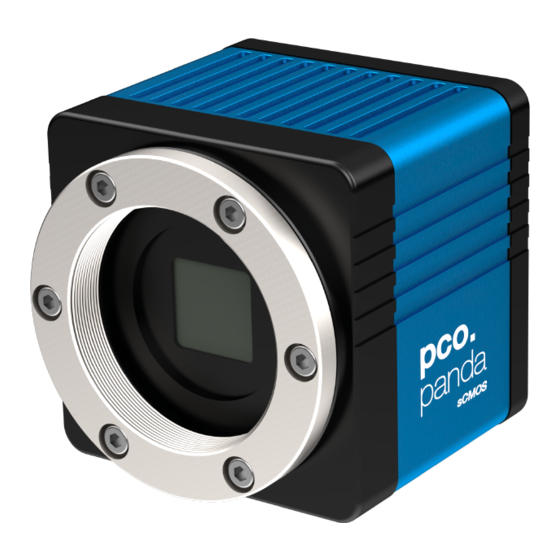
1. INTRODUCTION 1. INTRODUCTION Advantages of the pco.panda Features The pco.panda joins the ranks as our newest member of PCO’s state-of-the-art sCMOS sensor camera systems, which have revolutionized the scientific camera market since their introduction in 2010. Despite small-size dimensions of roughly 65 x 65 x 65 mm³, the new pco.panda camera system provides high quantum efficiency with low... -
Page 6: Safety Instructions
LIQUIDS DAMAGE CAMERA NOTICE If liquids have penetrated the device. Switch the camera off immediately, detach it from power and contact PCO's customer support. DAMAGED CAMERA HOUSING If the camera has been dropped or the camera body is damaged. NOTICE ... -
Page 7: System Components
3. SYSTEM COMPONENTS 3. SYSTEM COMPONENTS The camera system includes the following parts. Camera • C-mount optical connection • F-mount adapter optional • For standard C-mount / F-mount lenses and adapters Rear Panel • USB 3.1 Type C connector • LED indicates camera status (see A1.4) •... -
Page 8: Installation
USB 3.1 Gen1 • Windows 7 or higher 4.1 DRIVER Install PCO USB 3.0 Driver Always install the latest USB driver version. After these two screens the driver is completely installed. NVIDIA Cuda Driver Only relevant if an NVIDIA graphics card is used! GPU Processing is only working with NVIDIA graphics cards. -
Page 9: Camware
4. INSTALLATION 4.2 CAMWARE The Camware application software enables to control every camera parameter or setting. Images can be displayed on a monitor and may be downloaded and stored. The USB flash drive contains the installation files for the software for latest Windows operating systems in 32 &... -
Page 10: Quick Start
• Camera is connected to the PC 5.2 START Start Camware and the graphical user interface starts up: NOTE Always install latest Camware version to be able to use full function of your pco camera (www.pco.de/support). -
Page 11: First Image
5. QUICK START 5.3 FIRST IMAGE Follow the Instructions • Camware must be started • A View Window is shown automatically or open a new one • Start Live Preview • Right-click in the view window & apply Continuous Auto Range •... -
Page 12: Camware 4 Software
This chapter provides a detailed description of all Camware functions. Camware works with any kind of PCO camera. See PCO website for the latest version of this software. 6.1 CHAPTER OVERVIEW Chapter 6.2: cameras detected in Camware... -
Page 13: Camera Overview / List
Camera Overview The Camera Overview window supports management of more than one PCO cameras and displays a Camera List of the connected ones. Camware is able to Scan Cameras 2 or close a connected camera. It allows to define several different Camera... - Page 14 Link Preview Set to ‘Preview’ When Link Preview Set to ‘Preview’ is ticked the Preview is always active with the set parameters when starting a Live Preview 8 . In case this function is deactivated, the Live Preview always shows live images with the parameters of your active setting. Setting a higher exposure time for Preview Set and linking it to the Preview function is beneficial if Preview light conditions are different from those in recording situations.
-
Page 15: Camera Properties
6. CAMWARE 4 SOFTWARE 6.3 CAMERA PROPERTIES The Camera Properties window in Camware is the main interface for all camera settings. The active set selected within Camera List is adjusted here. The former main instance Camera Control (known from Camware 3.x) and the Convert Control (see 6.3.8) can be opened additionally. -
Page 16: Timing
6.3.1 TIMING This chapter explains the timing of the pco.panda in Camware. To basically understand the timing of the camera, read the chapter 6.3.2 ROLLING SHUTTER. Trigger Mode In this context trigger means exposure trigger, i.e. the trigger signal controls the exposure of a single image (light integration time). - Page 17 6. CAMWARE 4 SOFTWARE If the trigger rate of the external signal is higher than the maximum possible frame rate, every second trigger pulse is ignored. Therefore the actual frame rate drops to half of the external trigger rate. If the trigger rate is increased further, then only every third, every fourth etc.
-
Page 18: Rolling Shutter
6.3.2 ROLLING SHUTTER The pco.panda uses the rolling shutter mode. In this mode the pixel reset and exposure start is carried out line by line. Each line has the same exposure time, but a different start and end of exposure. Within one line, the exposure starts simultaneously for all pixels. - Page 19 6. CAMWARE 4 SOFTWARE Exposure time > Sensor frame readout time In case the required exposure time is longer than the frame readout time, the image sensor is completely exposed to light for some time (Show common time of ‘All Lines’ also see General Timing Diagram).
- Page 20 The band of simultaneous exposure is in this case (smallest possible height) at full resolution: For example: pco.panda 4.2: 10 µs / 12.136 µs (line time) = 1 → number of simultaneous lines. This is an example timing diagram for Trigger Mode Auto...
- Page 21 6. CAMWARE 4 SOFTWARE Details for External Exposure Start The detailed timing for external trigger includes system delay times, an adjustable additional delay time, and the jitter. NOTE The jitter t can be a maximum of one line time. Name Explanation Value jitter...
-
Page 22: Image Size
6.3.3 IMAGE SIZE The ROI (Region of Interest) selects only a part of the sensor to be read out, to speed up the frame-rate and to reduce the amount of image data. The decreased image size you see within Camware is a combination of reduced sensor resolution and software downsizing. -
Page 23: Sensor Control
6. CAMWARE 4 SOFTWARE 6.3.4 SENSOR CONTROL Offset Control Select Auto to automatically compensate dark current and signal drift of the offset. Select Off to deactivate Offset Control. The offset is recalculated if the exposure time is changed during a Record session. This applies also if any setting in Camera Properties is changed. - Page 24 Explanation of how the Acquire Mode External works in the different Trigger Modes (see 6.3.1): If set to External, the camera only records images if the external signal enables recording. The Acquire Mode is level controlled. That means at the level "high" image acquisition is possible, at the level "low"...
-
Page 25: Status
Additionally to Timestamp the Image Overlay function is available, see chapter 6.4. 6.3.6 STATUS Shows the current temperature level of the pco.panda camera. Electronics Temperature: shows the actual temperature of the FPGA Sensor Temperature: shows the actual sensor temperature. -
Page 26: Hardware Io Control
6.3.7 HARDWARE IO CONTROL Change setting via drop-down menu. Exposure Trigger If checked, a signal for External Exposure Start Trigger Mode (see chapter 6.3.1) is accepted at the Exposure Trigger SMA input #1. Exposure Trigger: On; Off Signal Polarity: Rising; Falling Aquire Enable If checked, a signal for Acquire Mode (see chapter 6.3.5) is accepted at the Acquire Enable SMA input #2. - Page 27 6. CAMWARE 4 SOFTWARE Detailed Explanation for Status Expos SMA #4 Signal Timing Setting in Camware: There are four different signal types selectable. The example timing diagram shows all four different possibilities: • Shows the exposure time of the first line •...
-
Page 28: Convert Control Dialog
GPU Processing On: Switch on in order to significantly reduce processing time (increases refresh rate of the live image). Only for NVIDIA graphic cards. Fast pco debayering: n/a (only color cameras) Color Refine Filter On: n/a (only color cameras) Noise Reduction... -
Page 29: Image Overlay
6. CAMWARE 4 SOFTWARE 6.4 IMAGE OVERLAY Open Image Overlay: these buttons allow easy switching between Camera Properties and Image Overlay windows. If not available, see 6.9.5 View Menu to activate this menu. This function enables an individually configurable image overlay, to display information within the images. -
Page 30: Recorder Tools
6.5 RECORDER TOOLS Recorder Tools provides Record and Play function, Play Settings and Record Settings. It can be found on the right lower side of Camware or, if closed, activated by View menu (see chapter 6.9.5) Record Start/Stop record: with Record button Second option: press enter or STRG+A to Start / Stop recording. - Page 31 6. CAMWARE 4 SOFTWARE Preview Settings If Preview with ext. signals is set to Yes: Trigger Mode Ext. Exp. Start or Acquire Mode External are active during Live Preview in case the Trigger Mode or Acquire Mode is enabled in the Preview set. Live Preview this...
-
Page 32: View Window
6.6 VIEW WINDOW Quick Scrolling Having recorded at least 50 images, you may scroll through the images quickly by holding down the left mouse button on the image number. Or enter the desired image number directly into the number field. More View Windows To open more View Windows from one camera: click View Window button 1 and Camware creates a new... -
Page 33: Recorder (Images)
6. CAMWARE 4 SOFTWARE 6.7 RECORDER (IMAGES) Once recording is done, small preview images (thumbnails) are built and displayed automatically in the Recorder (Images) docking window. It takes some time depending on the performance of your computer system and of the interface used. Clicking (left mouse button) within the upper scale bar 1 , adjusts the number of images shown by moving the mouse left or right. - Page 34 Right-Click Menu Right-click on thumbnails. Allows to rebuild all thumbnails and to search for events. Furthermore, the Set In / Out gives you the possibility to set values for a sequence, which can be played via play button. Reset In / Out discards these settings. Set In / Out is active: if you save / export your images, only the selected images are saved / exported (see 6.9.2).
-
Page 35: Settings Overview
6. CAMWARE 4 SOFTWARE 6.8 SETTINGS OVERVIEW Settings Overview shows the most important parameters of your camera(s) at a glance. If you have more than one camera connected, each camera and its parameters are listed. The parameters can only be changed using 6.3 Camera Properties. It is possible to easily switch between the Recorder (Images) section and the Settings Overview. -
Page 36: Auto Save
6.8.1 AUTO SAVE Auto Save helps to save recorded images or sequences in an easy way. There is no need to save each image / sequence separately from each connected camera. Therefore this function is very useful if you use more than one camera. Once configured Auto Save allows acquiring and saving as many images / sequences as needed during your experiment. - Page 37 6. CAMWARE 4 SOFTWARE Common Folder: select main folder for stored files RAW and Export File Type: select the type of RAW and compressed file Export Color Image: select to export color images (only for color cameras) Apply Automatic File Naming: if set to Yes, stored files automatically...
-
Page 38: Camware Menu Tabs & Features
2048 x 2048 yes / no upper Resolution The drop down list shows the PCO camera image sensor resolutions. Select the specific resolution and bit depth of the images to be opened. Color Select color mode (not available for pco.panda). -
Page 39: File Menu
This command imports a single image into the active image window. Only files with the extension and format *.b16 (=PCO proprietary binary image format) and *.tif (16 bit TIFF image format) can be imported. If the recorder is enabled, each imported image is transferred to the buffer shown in the picture number. - Page 40 Select: Yes, No. RAW 16bit RGB TIF File: Save RAW TIF without color balance. Select: Yes, No. Use Cache File: (n/a for pco.panda) General File Properties FIFO Buffer Size: Set the FIFO buffer size in number of images. This avoids gaps during file write delays.
-
Page 41: Camera Menu
6. CAMWARE 4 SOFTWARE Open AVI Codec Dialog Using Auto File Save and selecting AVI for video output affects stored video sequences. You only need to set this option, if you use Auto File Save see 6.8.1 Select the (compression) codec you want to use for stored sequences. -
Page 42: Acquisition Menu
6.9.4 ACQUISITION MENU Live Preview Live Preview for quick and easy adjusting and focusing of the camera. The active window is refreshed. To see another window, simply click on the window. Acquire Picture Only available if Trigger Mode is set to Soft Trigger, see 6.3.1 Acquire Sequence Starts recording images into the system memory according to Trigger Mode selection (see 6.3.1). - Page 43 6. CAMWARE 4 SOFTWARE Convert Control See 6.3.8 Toolbars and Docking Windows Standard toolbars of Camware are Recorder / Recorder Tools / Camera Overview / Camera Properties and Image Overlay. Additional Toolbars are displayable, but not essential: Main Toolbar / Extended Recorder / Math. Tool / Cursor. See below.
-
Page 44: Window Menu
Close Active Window Active window closes. Split The view window is split in four quadrants. Camera Overview Shows all connected cameras, e.g. 1 Camera 2 (pco.panda) 6.9.7 HELP MENU Contents (not available) Search for Help on (not available) Logging Enable Logging:... -
Page 45: View Window Menu
6. CAMWARE 4 SOFTWARE 6.9.8 VIEW WINDOW MENU Right-click in the View Window to open this menu. View Color Color window. View Window B (not available) Split Window Splits the View Window in four quadrants. Double-click on separator to undo. Stretched View Image is fitted into the View Window. - Page 46 Flip / Mirror Image is flipped or mirrored. Rotate Left / Right Rotates the image in steps of 90°. Set ‘File Save ROI’ To save just a part of the recorded image (region of interest), draw a rectangle with the mouse.
-
Page 47: Additional Features
6. CAMWARE 4 SOFTWARE 6.9.9 ADDITIONAL FEATURES White Balance by Mouse Change white balance by mouse: You only have to press the CTRL (STRG) and the shift button at the same time and select a white or gray area within the image by dragging a rectangle while holding the left mouse button. -
Page 48: Appendix
A1.2 QUANTUM EFFICIENCY CURVE A1.3 MECHANICAL DIMENSIONS A1.4 REAR PANEL A2 HARDWARE MOUNTING A2.1 USB CARD INSTALLATION A2.2 MOUNTING OF THE PCO.PANDA A3 F-MOUNT ADAPTER (OPTIONAL) A3.1 PCO F-MOUNT ADAPTER A3.2 CHANGE FROM C-MOUNT TO F-MOUNT A4 IMAGE FILE FORMATS A5 CUSTOMER SERVICE A5.1 SERVICE... -
Page 49: A1 Technical Data
A1 TECHNICAL DATA A1 TECHNICAL DATA A1.1 DATA SHEET image sensor type of sensor customized sCMOS resolution (h x v) 2048 x 2048 pixel pixel size (h x v) 6.5 µm x 6.5 µm sensor format / diagonal 13.3 x 13.3 mm / 18 mm shutter mode Rolling Shutter fullwell capacity (typ.) -
Page 50: A1.2 Quantum Efficiency Curve
A1.2 QUANTUM EFFICIENCY CURVE Quantum efficiency curve for the pco.panda 4.2. A1.3 MECHANICAL DIMENSIONS NOTE C-Mount flange focal distance: 17,52 mm All dimensions given in millimeter. -
Page 51: A1.4 Rear Panel
A1 TECHNICAL DATA A1.4 REAR PANEL Status LEDs (LED1: green / red; LED 2: orange) Color Description Red / green continuous Camera is booting Green Camera is ready for operation Orange continuous Arm camera / rec state off Orange blinking Recording on Red continuous Error... -
Page 52: A2 Hardware Mounting
A2 HARDWARE MOUNTING Instructions how to mount the pco.panda camera system. A2.1 USB CARD INSTALLATION An external USB 3.0 host controller card comes along with to each pco.panda camera. Hardware Installation First shut down your computer and install the USB 3.0 Host Controller. -
Page 53: A2.2 Mounting Of The Pco.panda
A2 HARDWARE MOUNTING A2.2 MOUNTING OF THE PCO.PANDA In order to ensure a proper function of the pco.panda, it is necessary to secure the USB cable by the fixing screws. The accompanying USB cable is screwable on both ends of the cable. -
Page 54: A3 F-Mount Adapter (Optional)
A3 F-MOUNT ADAPTER (OPTIONAL) A3.1 PCO F-MOUNT ADAPTER PCO's proprietary F-mount adapter for lenses with automatic diaphragm. Sets manually the lens aperture by turning the ring on the adapter. F-mount lenses without automatic diaphragm fastened camera's mount but aperture changed. -
Page 55: A3.2 Change From C-Mount To F-Mount
11 mm (2/3”), 16 mm (1”) or 22 mm (4/3”) diameter only. The pco.panda has a sensor diagonal of 18 mm, it follows that you have to use the ROI function for a shade less image while using the C-mount adapter with the two smaller C-mount diameters. -
Page 56: A4 Image File Formats
The 16 bit information is lost and cannot be recovered. pcoraw This 16 bit PCO file format is based on the new BigTIFF format, thus allowing for file size > 4GB. A new PCO proprietary compression scheme is added if necessary. - Page 57 A4 IMAGE FILE FORMATS Standard File Formats TIFF Tag Image File Format, version 6.0 and lower. There is a 16bit monochrome and color image format. Windows Bitmap Format, b/w or color 8 bit format-images, which have been saved in BMP format can be loaded later only as 8 bit images, i.e.
-
Page 58: A5 Customer Service
A5.3 RECYCLING If you want to dispose your camera, send it to PCO or take it to a local recycling center. The camera includes electronic devices, which can contain materials harmful to the environment. -
Page 59: A5.4 Trouble Shooting
A5 CUSTOMER SERVICE A5.4 TROUBLE SHOOTING If you have a question, which is not adequately addressed in this manual, contact PCO or your local dealer. To Speed up Your Request • • Short description of the Operating system (PC) problem •... -
Page 60: A6 Index
A6 INDEX Keyword Chapter Page NOTE: Auto File Save 6.8.1 The mentioned page is Averaging always starting Camware software page of a chapter! Codec Dialog 6.9.2 Contrast settings 6.3.8; 6.9.8 28; 45 Convert control 6.3.8 Cuda nvidia driver Data sheet A1.1 Demo mode (Camware) 6.9.1... -
Page 61: About Pco
– Dr. Emil Ott. In PCO’s first 30 years, Dr. Emil Ott took a company that he started right after finishing university and has built it into a major player in scientific and industrial cameras – and there’s plenty more to... - Page 62 pco.
Need help?
Do you have a question about the pco.panda 4.2 and is the answer not in the manual?
Questions and answers