Table of Contents
Advertisement
Quick Links
Advertisement
Table of Contents

Related Manuals for Pco edge 26


Summary of Contents for Pco edge 26
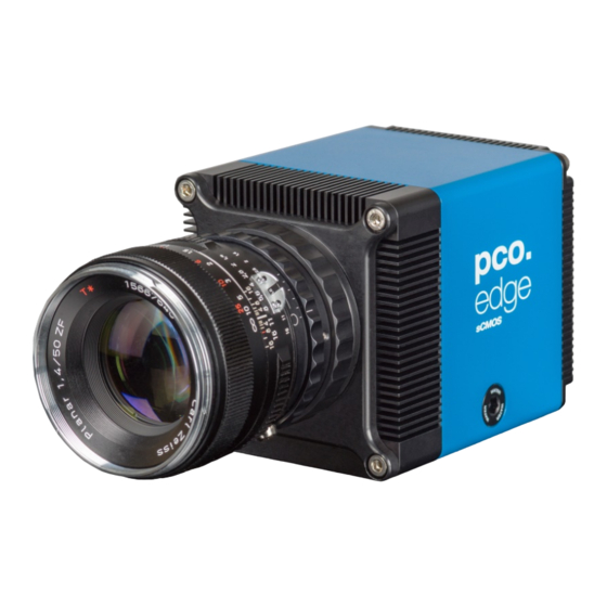
- Page 1 26 pco.
- Page 2 PCO asks you to carefully read and follow the instructions in this manual before using the pco.edge camera system. For any questions or comments, contact us at PCO. telephone +49 (0) 9441 2005 50 +49 (0) 9441 2005 20 email info@pco.de...
-
Page 3: Table Of Contents
A2.1 USB CARD INSTALLATION A2.2 CABLE MOUNTING A3 F-MOUNT ADAPTER A3.1 PCO F-MOUNT ADAPTER A3.2 CHANGE FROM F-MOUNT TO C-MOUNT A4 WATER COOLING OPTION PCO.AQUAMATIC II A4.1 SYSTEM COMPONENTS A4.2 FIRST TIME INSTALLATION A4.3 OPERATION A4.4 DIMENSIONS A4.5 USING YOUR OWN COOLING SYSTEM A5 CUSTOMER SERVICE A5.1 SERVICE... -
Page 4: Introduction
1. INTRODUCTION The pco.edge 26 Welcome to the pco.edge 26 system. This manual should help you to familiarize yourself with the camera and its functions. If you have any questions, please contact PCO directly. Main Features • True charge domain global shutter •... -
Page 5: Safety Instructions
LIQUIDS DAMAGE CAMERA NOTICE If liquids have penetrated the device: Switch the camera off immediately, detach it from power and contact PCO's customer support. DAMAGED CAMERA HOUSING If the camera has been dropped or the camera body is damaged: NOTICE ... -
Page 6: System Components
3. SYSTEM COMPONENTS The camera system includes the following parts. Camera • F-mount / C-mount optical connection • For standard C-mount / F-mount lenses and adapters Rear Panel • USB 3.1 Type C connector • LED indicates camera status (see A1.3) •... - Page 7 Digital Camera Tools (USB flash drive content) • pco.camware: software for camera control & image acquisition • Camera driver & tools • Software Development Kit (SDK) & demo programs in C and C++...
-
Page 8: Installation
This is only relevant if an NVIDIA graphics card is used! GPU Processing only functions with NVIDIA graphics cards. Update your NVIDIA driver for pco.camware. If an old driver version is installed, GPU Processing will not function, and image processing will be slow. -
Page 9: Camware Software
Windows operating systems in 32 & 64 bit. After a successful installation, you will find the program file Digital Camera Toolbox in your program directory and a pco.camware 32 / 64 button on your desktop. To uninstall the pco.camware program, navigate to Windows’ Add or remove programs from system settings. -
Page 10: Quick Start
• Camera is connected to the PC 5.2 START Start pco.camware to begin working with the graphical user interface: NOTE Always install the latest version of pco.camware to access full function of your camera (www.pco.de/support). -
Page 11: First Image
You should clearly see the object in the window To change Exposure time (e.g., the image is still either too dark or too bright) and to record and save images, see pco.camware manual for detailed information. NOTE Live preview: useful for fast and easy camera adjustment and... -
Page 12: Global Shutter
6. GLOBAL SHUTTER The pco.edge 26 uses the global shutter mode for image acquisition. First, all pixels are globally reset and its reset values are stored internally on the sensor. The image exposure starts. After exposure and readout, the sensor completes the correlated double sampling (CDS). -
Page 14: Camware 4 Software
7. CAMWARE 4 SOFTWARE This chapter contains only camera-specific additions to the pco.camware manual. All main functions and explanations can be found in the pco.camware manual. 7.1 HARDWARE IO CONTROL Settings can be changed with a drop-down menu. Exposure Trigger If On, a signal for External Exposure Start Trigger Mode is accepted at the Exposure Trigger SMA input #1. - Page 15 Enabling and Polarity of IO Signals The polarity of the input and output signals indicating their active states is selectable (positive or negative logic). The polarity of level-sensitive signals can be set to High (positive logic) or Low (negative logic). The polarity of edge-sensitive signals can be set to Rising (positive logic) or Falling (negative logic).
-
Page 16: Appendix
A1.1 DATA SHEET A1.2 QUANTUM EFFICIENCY CURVE A1.3 MECHANICAL DIMENSIONS A2 HARDWARE MOUNTING A2.1 USB CARD INSTALLATION A2.2 MOUNTING OF THE PCO.EDGE 26 A3 F-MOUNT ADAPTER A3.1 PCO F-MOUNT ADAPTER A3.2 CHANGE FROM C-MOUNT TO F-MOUNT A4 WATER COOLING OPTION PCO.AQUAMATIC II A4.1 SYSTEM COMPONENTS... -
Page 17: A1 Technical Data
A1 TECHNICAL DATA A1 TECHNICAL DATA A1.1 DATA SHEET Image sensor pco.edge 26 Type of sensor customized sCMOS Resolution (h x v) 5120 x 5120 pixel Pixel size (h x v) 2.5 µm x 2.5 µm Sensor format / diagonal 12.8 x 12.8 mm / 18.1 mm... -
Page 18: A1.2 Mechanical Dimensions
A1 TECHNICAL DATA A1.2 MECHANICAL DIMENSIONS All dimensions are in millimeters. 2D and 3D technical drawings are available on our website. 3D step files and further technical drawings are available on request. -
Page 19: A1.3 Rear Panel
A1 TECHNICAL DATA A1.3 REAR PANEL Status LEDs (LED1: green / red; LED 2: orange) Color Description Red / green continuous Camera is booting Green Camera is ready for operation Orange continuous Arm camera / rec state off Orange blinking Recording on Red continuous Error... -
Page 20: A2 Hardware Mounting
A2 HARDWARE MOUNTING A2 HARDWARE MOUNTING These instructions will show how to mount the pco.edge 26 camera system. A2.1 USB CARD INSTALLATION An external USB 3.0 / 3.1 Gen1 host controller card comes with each pco.edge 26 camera. Hardware Installation First shut down your computer and install the USB 3.0 / 3.1 Gen1... -
Page 21: A2.2 Cable Mounting
A2 HARDWARE MOUNTING A2.2 CABLE MOUNTING In order to ensure proper function of the pco.edge 26, it is necessary to secure the USB cable by the fixing screws. The accompanying USB cable is screwable on both ends of the cable. -
Page 22: A3 F-Mount Adapter
A3 F-MOUNT ADAPTER A3 F-MOUNT ADAPTER A3.1 PCO F-MOUNT ADAPTER When using PCO's proprietary F-mount adapter for lenses with automatic diaphragm, the aperture can be set manually by turning the ring on the adapter. F-mount lenses without automatic diaphragm can also be... -
Page 23: A3.2 Change From F-Mount To C-Mount
11 mm (2/3”), 16 mm (1”) or 22 mm (4/3”) diameter only. The pco.edge 26 has a sensor diagonal of 18.1 mm, therefore you have to use the ROI function for a shade-less image while using the... -
Page 24: A4 Water Cooling Option Pco.aquamatic Ii
Only use Innovatec Protect IP for the pco.aquamatic! Do not use or add any other coolant or normal water. If you need to add cooling liquid in order to maintain the tank level, contact PCO for additional supply. The coolant will turn yellow after some hours of operation. This is normal and not a sign of wear or malfunction. -
Page 25: A4.2 First Time Installation
Ensure the unit is placed on a flat and firm surface. Do not cover the cooling vents of the unit. Make certain there is free airflow around the pco.aquamatic for maximum cooling performance. All tubes and power cords must run kink-free. -
Page 26: A4.3 Operation
A4 WATER COOLING OPTION PCO.AQUAMATIC II A4.3 OPERATION To begin, connect the power out of the cooling unit with the power in of the pco.edge camera with the PCO WAT camera cable. The cooling unit provides two operation modes. Operation Mode on: the... -
Page 27: A4.4 Dimensions
Weight: 4kg (with filled coolant tank) A4.5 USING YOUR OWN COOLING SYSTEM You are not obliged to purchase the pco.aquamatic system — you may use your own water cooling device. A separate power supply will be provided to every pco.edge camera with water connection. The hardware of the pco.edge cameras with USB 3.1 interface is... -
Page 28: A5 Customer Service
A5.3 RECYCLING If you wish to dispose of your camera, return it to PCO or take it to a local recycling center. The camera includes electronic devices that may contain materials harmful to the environment. -
Page 29: A5.4 Troubleshooting
• Your setup: Software version Operating system Processor and memory Graphics card Firmware, Software and Driver Update You will find all necessary software and drivers on the accompanying USB storage device. For the latest versions check the PCO website (https://www.pco-tech.com/). -
Page 30: A6 Index
A6 INDEX A6 INDEX Keyword Chapter Page NOTE: Camware installation page listed Cleaning A5.1 always starting page of a chapter! Components camera system Cuda Nvidia driver Data sheet A1.1 Dimensions A1.2 Driver installation F-Mount First Image Global Shutter Hardware I/O Control Input / Output possibilities Installation Live preview... -
Page 31: About Pco
PCO’s success dates back to the 1980s and a research project of the founder, Dr. Emil Ott, who was working at the Technical University Munich for the Chair of Technical Electrophysics. While performing measurements with intensified slow scan cameras, Dr. - Page 32 pco.
Need help?
Do you have a question about the edge 26 and is the answer not in the manual?
Questions and answers