Table of Contents
Advertisement
Quick Links
Advertisement
Table of Contents

Related Manuals for Pco pco.edge 4.2 bi


Summary of Contents for Pco pco.edge 4.2 bi
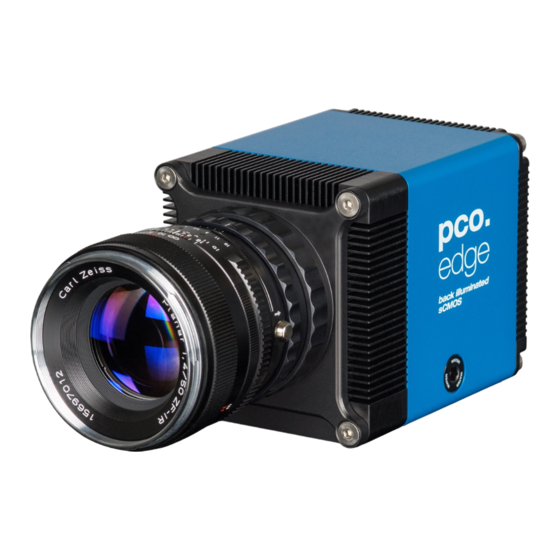
- Page 1 4.2 bi pco.edge 4.2 bi UV pco.
- Page 2 The information is subject to change without notice and does not represent a commitment on the part of PCO in the future. PCO hereby authorizes you to copy documents for non – commercial use within your organization only. In...
-
Page 3: Table Of Contents
A2.2 CABLE MOUNTING A2.3 DIRECT CAMERA MOUNTING A3 F-MOUNT ADAPTER A3.1 PCO F-MOUNT ADAPTER A3.2 CHANGE FROM F-MOUNT TO C-MOUNT A4 WATER COOLING OPTION PCO.AQUAMATIC II A4.1 SYSTEM COMPONENTS A4.2 FIRST TIME INSTALLATION A4.3 OPERATION A4.4 DIMENSIONS A4.5 YOUR OWN COOLING SYSTEM A5 CUSTOMER SERVICE A5.1 SERVICE... -
Page 4: Introduction
Innovations aren’t always about having that one big new idea. Unique technology also comes from evolution, combining existing and new technology. When our tried and trusted pco.edge series pools forces with modern back illuminated (bi) sensor technology, the result is our pco.edge 4.2 bi (UV). -
Page 5: Safety Instructions
LIQUIDS DAMAGE CAMERA NOTICE If liquids have penetrated the device. Switch the camera off immediately, detach it from power and contact PCO's customer support. DAMAGED CAMERA HOUSING If the camera has been dropped or the camera body is damaged. NOTICE ... -
Page 6: System Components
• Voltage input: 115 VAC - 230 VAC; IEC 60320 C14 plug • Power cord IEC 60320 C13 Digital Camera Tools (USB flash drive content) • pco.camware: software for camera control & image acquisition • Camera driver & tools •... -
Page 7: Installation
Only relevant if an NVIDIA graphics card is used! GPU Processing is only working with NVIDIA graphics cards. Update your NVIDIA driver for pco.camware. In case of an old driver version GPU Processing is not working. Therefore image processing is slow. -
Page 8: Camware Software
32 & 64 bit. After a successful installation, you find the program file Digital Camera Toolbox in your program directory and a pco.camware 32 / 64 button on your desktop. To uninstall the pco.camware program, use the software feature under Windows’... -
Page 9: Quick Start
• Camera is connected to the PC 5.2 START Start pco.camware and the graphical user interface starts up: NOTE Always install latest pco.camware version to be able to use full function of your camera (www.pco.de/support). -
Page 10: First Image
5.3 FIRST IMAGE Follow the Instructions • pco.camware must be started • A View Window is shown automatically or open a new one • Start Live Preview • Right-click in the view window & apply Continuous Auto Range • You may adjust Exposure time... -
Page 11: Rolling Shutter
6 ROLLING SHUTTER 6. ROLLING SHUTTER The pco.edge 4.2 bi (UV) uses the rolling shutter mode. In this mode the pixel reset and exposure start is carried out line by line. Each line has the same exposure time, but a different start and end of exposure. - Page 12 Exposure time > Sensor frame readout time In case the required exposure time is longer than the frame readout time, the image sensor is completely exposed to light for some time (Show common time of ‘All Lines’ also see General Timing Diagram).
- Page 13 6 ROLLING SHUTTER Exposure time < Sensor frame readout time In case the required exposure time is shorter than the frame readout time, the image is readout through an exposure band moving from the top to the bottom of the sensor. exposure stop &...
- Page 14 Details for External Exposure Start and External Exposure Control The detailed timing for external trigger includes system delay times, an adjustable additional delay time, and the jitter. Explanation for all Trigger Modes see pco.camware manual. NOTE The jitter t can be a maximum of one line time.
-
Page 15: Camware 4 Software
7 CAMWARE SOFTWARE 7. CAMWARE SOFTWARE This chapter contains only camera-specific additions to the pco.camware manual. All main functions and explanations can be found in the pco.camware manual. 7.1 HARDWARE IO CONTROL Change setting are done via drop-down menu. Exposure Trigger If checked, a signal for External Exposure Start Trigger Mode is accepted at the Exposure Trigger SMA input #1. - Page 16 The polarity of edge-sensitive signals can be set to Rising (positive logic) or Falling (negative logic). Detailed Explanation for Status Expos SMA #4 Signal Timing Setting in pco.camware: There are four different signal types selectable. The example timing diagram shows all four different possibilities: •...
-
Page 17: Appendix
A2.2 CABLE MOUNTING A2.3 DIRECT CAMERA MOUNTING A3 F-MOUNT ADAPTER A3.1 PCO F-MOUNT ADAPTER A3.2 CHANGE FROM F-MOUNT TO C-MOUNT A4 WATER COOLING OPTION PCO.AQUAMATIC II A4.1 SYSTEM COMPONENTS A4.2 FIRST TIME INSTALLATION A4.3 OPERATION A4.4 DIMENSIONS A4.5 YOUR OWN COOLING SYSTEM A5 CUSTOMER SERVICE A5.1 SERVICE... -
Page 18: A1 Technical Data A1.1 Data Sheet
A1 TECHNICAL DATA A1.1 DATA SHEET Image sensor pco.edge 4.2 bi (UV) Type of sensor Customized sCMOS Resolution (h x v) 2048 x 2048 pixel Pixel size (h x v) 6.5 μm x 6.5 μm Sensor format / diagonal 13.3 x 13.3 mm / 18.8 mm... -
Page 19: A1.2 Mechanical Dimensions
A1 TECHNICAL DATA A1.2 MECHANICAL DIMENSIONS NOTE C-Mount flange focal distance: 17.52 mm All dimensions given in millimeter. 2D and 3D technical drawings are available on our website 3D step files and further technical drawings are available on request. -
Page 20: A1.3 Rear Panel
A1.3 REAR PANEL Status LEDs (LED1: green / red; LED 2: orange) Color Description Red / green continuous Camera is booting Green Camera is ready for operation Orange continuous Arm camera / rec state off Orange blinking Recording on Red continuous Error Interface Connector USB 3.1 plug Type-C screwable;... -
Page 21: A2 Hardware Mounting
A2 HARDWARE MOUNTING A2 HARDWARE MOUNTING Instructions how to mount the pco.edge 4.2 bi (UV) camera system. A2.1 USB CARD INSTALLATION An external USB 3.0 / 3.1 Gen1 host controller card comes along with to each pco.edge 4.2 bi (UV) camera. -
Page 22: A2.2 Cable Mounting
A2.2 CABLE MOUNTING In order to ensure a proper function of the pco.edge 4.2 bi (UV), it is necessary to secure the USB cable by the fixing screws. The accompanying USB cable is screwable on both ends of the cable. -
Page 23: A2.3 Direct Camera Mounting
A2 HARDWARE MOUNTING A2.3 DIRECT CAMERA MOUNTING The hardware design allows to mount the camera very close to an optical setup (e.g. a microscope) without F- or C-mount adapter but with the help of a rubber ring. This allows to reduce the distance from the focal plane of the sensor to the adaption plate to only 6.18 mm. -
Page 24: A3 F-Mount Adapter
A3 F-MOUNT ADAPTER A3.1 PCO F-MOUNT ADAPTER PCO's proprietary F-mount adapter for lenses with automatic diaphragm. Sets manually the lens aperture by turning the ring on the adapter. F-mount lenses without automatic diaphragm fastened camera's mount but aperture changed. Adjust Back Focal Length To adjust the back focal length (e.g. -
Page 25: A3.2 Change From F-Mount To C-Mount
11 mm (2/3”), 16 mm (1”) or 22 mm (4/3”) diameter only. The pco.edge bi has a sensor diagonal of 18.8 mm, it follows that you have to use the ROI function for a shade less image while using the C-mount adapter with the two smaller C-mount diameters. -
Page 26: A4 Water Cooling Option Pco.aquamatic Ii
(water tank) should be checked from time to time. Only use Innovatec Protect IP for the pco.aquamatic! Do not use or add any other coolant or normal water! If you need to add cooling liquid in order to maintain the tank level, contact PCO for additional supply. -
Page 27: A4.2 First Time Installation
Take care to place the unit on a flat and firm surface. Do not cover the cooling vents of the unit. Ensure free airflow around the pco.aquamatic for maximum cooling performance. All tubes and power cords need to run kink-free. -
Page 28: A4.3 Operation
A4.3 OPERATION First connect the power out of the cooling unit with the power in of the pco.edge camera by using the PCO WAT camera cable. The cooling unit provides two operation modes. Operation Mode on: the cooling unit turns on and provides permanently power to the camera. -
Page 29: A4.4 Dimensions
Weight: 4kg (completely filled coolant tank) A4.5 YOUR OWN COOLING SYSTEM You are not obliged to purchase the pco.aquamatic system - you may use your own water cooling device. A separate power supply will be provided to every pco.edge camera with water connection. The hardware of the pco.edge cameras with USB 3.1 interface is... -
Page 30: A5 Customer Service
A5.3 RECYCLING If you want to dispose your camera, send it to PCO or take it to a local recycling center. The camera includes electronic devices, which can contain materials harmful to the environment. -
Page 31: A5.4 Trouble Shooting
Serial number • Your setup: Software version Operating system Processor and memory Graphics card Firmware, Software and Driver Update You will find all necessary software and drivers on the accompanying USB storage device. For the latest versions check PCO website. -
Page 32: A6 Index
A6 INDEX Keyword Chapter Page NOTE: Camware installation The mentioned page is Cleaning A5.1 always starting page of a chapter! Components camera system Cuda Nvidia driver Data sheet A1.1 Dimensions A1.2 Driver installation F-Mount First Image Hardware I/O Control Input / Output possibilities Installation Live preview Logfiles... -
Page 33: About Pco
– Dr. Emil Ott. In PCO’s first 30 years, Dr. Emil Ott took a company that he started right after finishing university and has built it into a major player in scientific and industrial cameras – and there’s plenty more to... - Page 34 pco.
Need help?
Do you have a question about the pco.edge 4.2 bi and is the answer not in the manual?
Questions and answers