Table of Contents
Advertisement
Quick Links
Advertisement
Table of Contents

Related Manuals for RADIOMETER ABL 77 Series


Summary of Contents for RADIOMETER ABL 77 Series
- Page 1 1. Introduction ABL™77 Series 2. Analyzer Description Blood Gas and Electrolyte 3. Troubleshooting Analyzer 4. Test and Calibration 5. Dismantling 6. Replacements Service Manual 7. Re-Assembly 8. Maintenance 9. Spare Parts Service Notes Date of Issue...
- Page 2 By your use of the instrument you agree to the terms of this Agreement and the Microsoft End User License Agreement. If you do not accept or agree to the terms you should promptly contact your Radiometer representative for a return of the instrument and a refund of your money.
-
Page 3: Table Of Contents
ABL77 Service Manual Table of Contents Table of Contents Introduction This manual describes how to service the ABL™77 Series analyzer. Contents This manual contains the following topics. 1. Introduction ....................1-1 Overview .................... 1-1 Service Policy..................1-2 Test Equipment and Tools..............1-5 ABL77 Identification................ - Page 4 Table of Contents ABL77 Service Manual Table of Contents, Continued 4. Test and Calibration Procedures ..............4-1 Overview .................... 4-1 Verify the Fluid Transport System ............. 4-3 Calibration Lines Procedure ............... 4-5 Testing the Valve Connections............4-11 Valve Test Procedures ..............4-13 Check Valve Fluidics System ..........
- Page 5 ABL77 Service Manual Table of Contents Table of Contents, Continued Roller Wheel and Roller Pump............5-20 Waste Pump Head and Waste Pump ..........5-22 Original Valve Board / Manifold Assembly........5-25 Valve Board with Replaceable Valves ..........5-27 Valve Board Styles ................5-31 Electronics Module.................
- Page 6 Table of Contents ABL77 Service Manual Table of Contents, Continued Cabling ....................6-33 Disk Drive Cable ................6-36 LCD Display Cable ................6-38 Backlight Inverter Cable..............6-40 Touch Screen Cable................6-42 Main Analog Cable................6-43 Analog Power Cable................. 6-44 Power Board Cable................6-45 A/D Cable –...
- Page 7 ABL77 Service Manual Table of Contents Table of Contents, Continued Electronics Module................. 7-37 Rear Panel Assembly................ 7-37 Fan Assembly ................... 7-38 Electronics Chassis And Battery Cage ..........7-39 Battery Control Board ..............7-40 Electronics Shelf................7-42 Electronic Boards ................7-44 Touch Screen And CPU Boards Assembly......
- Page 8 Table of Contents ABL77 Service Manual Table of Contents, Continued Service Notes Date of Issue Rev. F...
-
Page 9: Introduction
ABL77 Service Manual Chapter 1: Introduction 1. Introduction Overview Introduction This chapter gives an introduction to the servicing of the ABL™77 analyzer and important information for understanding the procedures and requirements. This chapter contains the following topics. Contents Overview....................1-1 Service Policy .................. -
Page 10: Service Policy
• The recommended maintenance procedures outlined in the Operator’s and Service Manuals are performed. • The accessories and spare parts specified by Radiometer Medical A/S are used. Warranty claims for parts which suffer from physical damage, unauthorized attempted repair, or exposure to conditions other than those specified by Radiometer Medical A/S (e.g., temperature, line voltage outside specified limits) - Page 11 ABL77 Service Manual Chapter 1: Introduction Service Policy, Continued Repair level The repair level outlines the extent to which it is allowed to dismantle an analyzer in the process of troubleshooting and repair. This level is limited for several reasons such as: the need for specialized test equipment, special environmental requirements etc., and is optimized in relation to cost of parts, time for repair, etc.
- Page 12 Chapter 1: Introduction ABL77 Service Manual Service Policy, Continued WARNING/ CAUTION: Follow legal requirements and local rules for safe work practices with CAUTION: chemicals. CAUTION: Working with blood gas analyzers may result in contact with blood remnants and with harsh disinfectants. During the various procedures wear suitable protection gear (gloves, face protection, and protective body clothing) and follow legal requirements and local rules for safe work practices.
-
Page 13: Test Equipment And Tools
ABL77 Service Manual Chapter 1: Introduction Test Equipment and Tools Required To carry out the procedures for servicing the analyzer, the following test equipment and equipment and tools are required: Parts marked with “N/A” in the REF column are tools to be purchased locally. -
Page 14: Abl77 Identification
Chapter 1: Introduction ABL77 Service Manual ABL77 Identification Introduction This section explains the identification system for the ABL77 product. ABL77 Each individual analyzer consists of a number of separate elements, some using a identification unique identification system. These numbers are used for a large variety of purposes, e.g. -
Page 15: Panel Options
ABL77 Service Manual Chapter 1: Introduction Panel Options Introduction This section explains the panel options available with the ABL77 analyzer. When servicing an analyzer it should always be returned to the same settings. Available The ABL77 can be configured for the following options: options •... -
Page 16: Analyzer Description
ABL77 Service Manual Chapter 2: Analyzer Description 2. Analyzer Description Overview Introduction This chapter provides a general description of the analyzer modules, the electronic boards, the electronics wiring diagrams, and the fluidics system. This chapter includes various drawings for use during servicing. The drawings indicate the location of connection points and general identification. -
Page 17: Functional Description
Chapter 2: Analyzer Description ABL77 Service Manual Functional Description Introduction This section provides a general introduction to the analyzer. Overview The ABL77 Analyzer is an electromechanical instrument designed to measure blood gas, pH, and electrolyte concentrations of whole blood. The heart of the ABL77 analyzer is a 486 SX single board computer. It operates on ®... -
Page 18: Sci Installation
ABL77 Service Manual Chapter 2: Analyzer Description SCi Installation Sensor cassette When a new sensor cassette is installed on the analyzer, the software will perform installation an initialization procedure to prepare the cassette for use. This initialization process consists of a preparatory hydration phase followed by a number of calibration attempts. - Page 19 Chapter 2: Analyzer Description ABL77 Service Manual This page intentionally left blank Rev. F...
-
Page 20: Calibration
ABL77 Service Manual Chapter 2: Analyzer Description Calibration Introduction The user can define the frequency of automatic two-point calibrations. The possible intervals are 1, 2, 3 or 4 hours. The Calibration option on the Main Menu is used to initiate a manual two- point calibration as desired. Hydration If the calibration is more than 30 minutes past the scheduled time, a preliminary flush of Cal1 solution is performed prior to the two-point calibration. - Page 21 Chapter 2: Analyzer Description ABL77 Service Manual Calibration, Continued • During the first phase of the calibration process, the roller wheel is activated Calibration- phase 1 along with valves 1 and 3. This flushes Cal2 solution through the sensor cassette measuring chamber (see Figure 2-1).
- Page 22 ABL77 Service Manual Chapter 2: Analyzer Description Calibration, Continued Calibration- Part Function phase 1 (continued) Cal1 solution (Calibration solution – Level 1) Cal2 solution (Calibration solution – Level 2) Waste bag Cal Pack Main waste line Manifold Manifold luers Side waste line Valves L1, L2 and L3 Cassette measuring chamber Roller wheel...
- Page 23 Chapter 2: Analyzer Description ABL77 Service Manual Calibration, Continued • During the second phase of the calibration, the roller wheel is activated along Calibration – phase 2 with valves 2 and 3. This flushes Cal1 solution through the sensor cassette measuring chamber (see Figure 2-2).
- Page 24 ABL77 Service Manual Chapter 2: Analyzer Description Calibration, Continued Calibration – Part Function phase 2 (continued) Cal1 solution (Calibration solution – Level 1) Cal2 solution (Calibration solution – Level 2) Waste bag Cal Pack Main waste line Manifold Manifold luers Side waste line Valves L1, L2 and L3 Cassette measuring chamber...
- Page 25 Chapter 2: Analyzer Description ABL77 Service Manual Calibration, Continued • Calibration sensitivity values are calculated based on these two measurements. Sensitivity values • These sensitivity values are compared to the acceptable range. • If the values are acceptable, the calibration is complete. •...
- Page 26 ABL77 Service Manual Chapter 2: Analyzer Description This page intentionally left blank Rev. F 2-11...
-
Page 27: Sample Analysis
Chapter 2: Analyzer Description ABL77 Service Manual Sample Analysis Introduction The Analysis option on the Main Menu allows the user to initiate a sample analysis. Analysis – initial Pressing the Analysis icon initiates a brief flush of Cal1 solution to ensure the tip flush of the inlet probe is filled with fluid. - Page 28 ABL77 Service Manual Chapter 2: Analyzer Description Sample Analysis, Continued Analysis – phase Part Function 1 aspiration (continued) Cal1 solution (Calibration solution – Level 1) Cal2 solution (Calibration solution – Level 2) Waste bag Cal Pack Main waste line Manifold Manifold luers Side waste line Valves L1, L2 and L3...
- Page 29 Chapter 2: Analyzer Description ABL77 Service Manual Sample Analysis, Continued • The analyzer prompts the user to remove the sample and lower the inlet probe Analysis – phase 2 aspiration • The analyzer then advances the sample a second time to complete the positioning of the sample (see Figure 2-4).
- Page 30 ABL77 Service Manual Chapter 2: Analyzer Description Sample Analysis, Continued Analysis – phase Part Function 2 aspiration (continued) Cal1 solution (Calibration solution – Level 1) Cal2 solution (Calibration solution – Level 2) Waste bag Cal Pack Main waste line Manifold Manifold luers Side waste line Valves L1, L2 and L3...
- Page 31 Chapter 2: Analyzer Description ABL77 Service Manual Sample Analysis, Continued • Following the sample measurement, the roller wheel is activated along with Analysis – sample flush valves 2 and 3 to flush cal 1 solution through the sensor cassette (see Figure 2-5). •...
- Page 32 ABL77 Service Manual Chapter 2: Analyzer Description Sample Analysis, Continued Analysis – Part Function sample flush (continued) Cal1 solution (Calibration solution – Level 1) Cal2 solution (Calibration solution – Level 2) Waste bag Cal Pack Main waste line Manifold Manifold luers Side waste line Valves L1, L2 and L3 Cassette measuring chamber...
-
Page 33: Module Descriptions
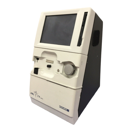
Chapter 2: Analyzer Description ABL77 Service Manual Module Descriptions Overview This section describes the analyzer, individual modules and external components. Detailed diagrams of the modules and connections are included with each module. ABL77 analyzer This sub-section describes the analyzer, external components and disposables. Front view of Figure 2-6 shows the front view and sensor cassette of the ABL77 analyzer. - Page 34 ABL77 Service Manual Chapter 2: Analyzer Description Module Descriptions, Continued Rear view of Figure 2-7 shows the rear view and cal pack of the ABL77 analyzer. analyzer Figure 2-7 Part Function Main housing assembly Cal pack Electronics module Continued on next page Rev.
- Page 35 Chapter 2: Analyzer Description ABL77 Service Manual Module Descriptions, Continued Battery charger The external battery charger is for use with the ABL77 analyzer only. It provides the source of AC power to the system when plugged into an active electrical socket (see Figure 2-8).
- Page 36 ABL77 Service Manual Chapter 2: Analyzer Description Module Descriptions, Continued Barcode scanner The barcode scanner, shown below, is for use with the ABL77 analyzer only (see Figure 2-10). Figure 2-10 Barcode scanner The barcode scanner holder may be installed on the analyzer in any location that is holder convenient (see Figure 2-11).
- Page 37 Chapter 2: Analyzer Description ABL77 Service Manual Module Descriptions, Continued Disposables The ABL77 has two key disposable components, a sensor cassette and a cal pack. These disposable items are designed for a limited number of uses throughout a specified in-use life. After use, these components are considered a biohazard and should be disposed of in a safe and proper manner.
- Page 38 ABL77 Service Manual Chapter 2: Analyzer Description Module Descriptions, Continued Cal pack The cal pack contains the solutions used to calibrate and flush the sensor cassette (see Figure 2-13). The cal pack also contains a waste bag to collect all samples, solutions and other fluids that are processed through the analyzer.
- Page 39 Chapter 2: Analyzer Description ABL77 Service Manual Module Descriptions, Continued ABL77 block Figure 2-14 displays the inter-connection of primary and secondary components of diagram the ABL77 analyzer. Figure 2-14 2-24 Rev. F...
- Page 40 ABL77 Service Manual Chapter 2: Analyzer Description This page intentionally left blank Rev. F 2-25...
-
Page 41: Upper Module
Chapter 2: Analyzer Description ABL77 Service Manual Upper Module Introduction This section provides a description of the upper module of the ABL77 analyzer. The upper module contains the display components and disk drive (see the following figures). • Resistive Touch Screen: Located in front of the LCD display. It reacts to gentle Components pressure from a finger or wand to supply the ABL77 with user input. - Page 42 ABL77 Service Manual Chapter 2: Analyzer Description Module Descriptions, Continued Diagrams Figure 2-15 Part Function Upper housing Disk drive Disk drive cable Touch screen cable LCD display cable Backlight inverter cable Backlight inverter Insulating tape Housing bracket Touch screen panel LCD display Continued on next page Rev.
- Page 43 Chapter 2: Analyzer Description ABL77 Service Manual Module Descriptions, Continued Diagrams (continued) Figure 2-16 Continued on next page 2-28 Rev. F...
- Page 44 ABL77 Service Manual Chapter 2: Analyzer Description Module Descriptions, Continued Diagrams Part Function (continued) Backlight inverter board screws Insulating tape Backlight inverter board Housing screws Housing bracket Copper tape Disk drive screws Disk drive washers Copper cloth tape Disk drive LCD display Touch screen panel Upper housing...
-
Page 45: Lower Module
Chapter 2: Analyzer Description ABL77 Service Manual Lower Module Introduction This section provides a description of the lower module of the ABL77 analyzer. The lower module contains the following components and related mechanisms. • The Valve Board routes all fluids through a system of three 3-way valves. The Components valve board contains the sensor cassette connector and connections to the analog board, door sensor, roller pump and waste pump motor. - Page 46 ABL77 Service Manual Chapter 2: Analyzer Description Module Descriptions, Continued Valve board Layout of the Valve Board, REF: 902-812 (Figure 2-17). SENSOR BOSS SENSOR LUER 41449 / B 41477 SERVICE BOARD ABL70-77 ASSY REV : 2587 REVISION Figure 2-17 The Valve Board Assembly (REF: 902-811) includes the valves and tubing (Figure 2-18).
- Page 47 Chapter 2: Analyzer Description ABL77 Service Manual Module Descriptions, Continued Lower module - Front Figure 2-19 Part Function Waste drain Waste pump Sensor cassette nest Roller pump wheel Printer Continued on next page 2-32 Rev. F...
- Page 48 ABL77 Service Manual Chapter 2: Analyzer Description Module Descriptions, Continued Lower module - Rear Figure 2-20 Part Function Printer Sensor luer connector Roller pump motor I/O cable connector Valve board Sensor cable connector Opto sensor Manifold Waste pump Rev. F 2-33...
-
Page 49: Electronics Module
Chapter 2: Analyzer Description ABL77 Service Manual Electronics Module Introduction This section provides a description of the electronics module of the ABL77 analyzer. • Electronics Boards Components • Analog board • Power distribution board • Interface board • ChipDisk • LCD adapter board •... - Page 50 ABL77 Service Manual Chapter 2: Analyzer Description Module Descriptions, Continued Electronics Boards Analog board The analog board (REF: 902-682) contains a microprocessor and custom algorithms that control valve, motor, and sensor operations (see Figure 2-21). The onboard processor performs various operations such as thermistor control, roller pump motor control, and sensor signal A to D conversions.
- Page 51 Chapter 2: Analyzer Description ABL77 Service Manual Module Descriptions, Continued Power The power distribution board (REF: 902-838) receives power from the battery distribution control board and routes the power to the electronic boards assembly and the board analog board (see Figure 2-22). Figure 2-22 Interface board The interface board (REF: 902-681) contains the internal speaker and the coin cell battery that supplies the CPU with power to maintain the computer settings See...
- Page 52 ABL77 Service Manual Chapter 2: Analyzer Description Module Descriptions, Continued LCD adapter The LCD adapter board (REF: 902-678) converts signals from the CPU for use by board the LCD display (see Figure 2-25). The LCD adapter board is a component of the CPU board.
- Page 53 Chapter 2: Analyzer Description ABL77 Service Manual Module Descriptions, Continued CPU board The CPU board (REF: 902-679) consists of a 486 SX microcomputer with at least 8 MB memory, VGA, serial and parallel ports, and floppy disk control (see Figure 2-27). The interface board connects the microcomputer to its battery support and speaker as well as interfacing with the printer and the COM 1 port.
- Page 54 ABL77 Service Manual Chapter 2: Analyzer Description Module Descriptions, Continued Battery control The battery control board (REF: 902-680) monitors system power requirements board and diverts the incoming AC power to and from the battery pack accordingly (see Figure 2-29). The batteries are charged in a controlled manner to prevent over- charging.
- Page 55 Chapter 2: Analyzer Description ABL77 Service Manual Module Descriptions, Continued Electronics module assembly Figure 2-30 Continued on next page 2-40 Rev. F...
- Page 56 ABL77 Service Manual Chapter 2: Analyzer Description Module Descriptions, Continued Rear Panel with External Connections Diagrams Figure 2-31 Part Function Barcode / keyboard port cable Power switch cable Ethernet port cable COM1 port cable Fan assembly cable Continued on next page Rev.
- Page 57 Chapter 2: Analyzer Description ABL77 Service Manual Module Descriptions, Continued Diagrams (continued) Figure 2-32 Part Function COM1 port Barcode / keyboard port Charger port Ethernet port Power switch Battery door Continued on next page 2-42 Rev. F...
- Page 58 ABL77 Service Manual Chapter 2: Analyzer Description Module Descriptions, Continued Barcode / The barcode scanner port is a 5 pin DIN connector that sends the signals to the keyboard interface board. This port is also used for connecting a keyboard to the analyzer for connector testing purposes.
- Page 59 Chapter 2: Analyzer Description ABL77 Service Manual Module Descriptions, Continued Battery Pack Battery pack The battery pack contains 12 nickel metal hydride (NiMH) cells (see Figure 2-33). The pack has a nominal DC voltage of 14.4 and a rated capacity of 3.8 Ah. The battery pack stores power for use by the analyzer when not connected to an AC power source.
- Page 60 ABL77 Service Manual Chapter 2: Analyzer Description Module Descriptions, Continued Optimal battery The lifetime of a battery pack is affected by various conditions. Elevated pack life temperatures, long periods of inactivity and incomplete charging will diminish the expected lifetime and operation of the battery pack. NiMH batteries operate at their optimal capacity when regularly exercised and allowed to discharge to a level other than full capacity.
-
Page 61: Overview
ABL77 Service Manual Chapter 3: Troubleshooting 3. Troubleshooting Overview Introduction This chapter provides troubleshooting information for errors or messages that may occur during the operation of the ABL77 analyzer. This chapter contains the following topics. Contents Overview....................3-1 General Information ..................3-2 Cautions and Warnings ................. -
Page 62: General Information
Chapter 3: Troubleshooting ABL77 Service Manual General Information Introduction This section provides information regarding cautions and warnings as well as information on normal operation that can be fundamental to understanding error conditions. -
Page 63: Cautions And Warnings
ABL77 Service Manual Chapter 3: Troubleshooting Cautions and Warnings Introduction This topic emphasizes important safety issues. Please review before proceeding with any troubleshooting steps. WARNING/ WARNING: Always turn the power off and unplug the system when cleaning the CAUTION: analyzer. CAUTION: Always remember to exercise Universal Precautions when handling contaminants and biohazardous materials (OSHA standard 1910.1030). -
Page 64: General Guidelines
Chapter 3: Troubleshooting ABL77 Service Manual General Guidelines Introduction This topic describes additional information pertinent to the use of the ABL77 analyzer. • The following tools are recommended for various service procedures: Suggested tools • A Sample Path Obstruction Tools (REF: 905-674) kit can assist in removing fluid path obstructions. -
Page 65: Hardware Screen
ABL77 Service Manual Chapter 3: Troubleshooting Hardware Screen Introduction This topic describes the various features of the Hardware screen that can assist in troubleshooting. • The Hardware screen allows manual control of basic analyzer functions. Description of Hardware • The three soft keys across the bottom of the screen allow the user to initiate a screen single flush of Cal1 solution, Cal2 solution, or a single aspiration through the inlet probe (see Figure 3-2). - Page 66 Chapter 3: Troubleshooting ABL77 Service Manual Hardware Screen, Continued • Activate the heater circuit by selecting the check box labelled Heater ON (see Description of Hardware Figure 3-3). The temperature reading as measured by the thermistor (located in screen the sensor cassette) is displayed and labelled Th. (continued) Figure 3-3 •...
- Page 67 ABL77 Service Manual Chapter 3: Troubleshooting Hardware Screen, Continued • A relative charge reading for the battery pack is displayed (Bat) as well as the Description of Hardware function of the battery charger (Pak) (see Figure 3-4). An inlet flap sensor screen indicator is also displayed (Door).
-
Page 68: Reference Table Of Problems, Causes And Corrective Actions
Chapter 3: Troubleshooting ABL77 Service Manual Reference Table of Problems, Causes and Corrective Actions Introduction This section summarizes, in table form, the various types of problems and error conditions which may be encountered during the operation of the ABL77 analyzer. -
Page 69: Reference Table
ABL77 Service Manual Chapter 3: Troubleshooting Reference Table Introduction This table offers a convenient reference to problems, their causes and the recommended corrective action. The most frequent cause for each problem is listed first followed by less frequent causes. Problem Probable Cause Corrective Action Calibration Failure –... - Page 70 Chapter 3: Troubleshooting ABL77 Service Manual Reference Table, Continued Problem Probable Cause Corrective Action Calibration, Initialization, or Insufficient 5V supply of power Proceed to Chapter 4, Test and QC failures of the Hct channel Calibration Procedures to with multiple sensor cassettes check the 5 volt power supply.
- Page 71 ABL77 Service Manual Chapter 3: Troubleshooting Reference Table, Continued Problem Probable Cause Corrective Action Power – no AC power A/C not reaching the analyzer Verify active power source and due to poor power cord ensure all cord connections are connection or inactive power secure source Battery charger malfunction...
- Page 72 Chapter 3: Troubleshooting ABL77 Service Manual Reference Table, Continued Problem Probable Cause Corrective Action Printer – Other Printout light or missing pixels / Replace printer. See Chapter 5, not sensing paper: the thermal Dismantling. If corrosion is printer can have a component present, investigate source of malfunction or this problem can fluid contamination...
- Page 73 ABL77 Service Manual Chapter 3: Troubleshooting Reference Table, Continued Problem Probable Cause Corrective Action QC - results out of range Incorrect handling Review the user's QC technique. Stress the importance of If failures are occurring with thorough mixing and aspirating multiple sensor cassettes over the sample immediately after time see "Calibration,...
- Page 74 Chapter 3: Troubleshooting ABL77 Service Manual Reference Table, Continued Problem Probable Cause Corrective Action Screen – Touch Screen non Main CPU Replace the main CPU. See functional Chapter 5, Dismantling Description: there is no response LCD Display Cable Check the connection. Replace when the touch screen is pressed as necessary.
- Page 75 ABL77 Service Manual Chapter 3: Troubleshooting Reference Table, Continued Problem Probable Cause Corrective Action Temperature Errors SCi temperature circuit failure Replace the sensor cassette. See Chapter 4, Test and Calibration Procedures for further instructions on checking the heater circuit Valve Board - worn or corroded Replace the valve board.
-
Page 76: System Messages
Chapter 3: Troubleshooting ABL77 Service Manual System Messages Introduction This section lists system messages, provides an interpretation and any recommended corrective action. This section groups system messages in categories. Reference error messages using its unique error number. System messages This table provides an interpretation of the message and suggests corrective action. Error # Message Interpretation... - Page 77 ABL77 Service Manual Chapter 3: Troubleshooting Reference Table, Continued Error # Message Interpretation Corrective Action 1100 Printer Errors 1101 Printer access denied General failure of the Shutdown the analyzer operating system. power through the Main Menu Shutdown button then turn the analyzer back on to re-boot the computer 1102 The printer is out of paper.
- Page 78 Chapter 3: Troubleshooting ABL77 Service Manual Reference Table, Continued Error # Message Interpretation Corrective Action 1300 Sensor Errors 1301 Sensor cassette is not Analyzer does not sense the Re-seat sensor cassette. If connected. presence of a sensor cassette message persists after re- seating try another sensor cassette.
- Page 79 ABL77 Service Manual Chapter 3: Troubleshooting Reference Table, Continued Error # Message Interpretation Corrective Action 1306 QC Level 1 is required Mandatory QC interval has Perform the required before analysis can be been reached. Analysis will BG/Lytes QC measurement performed not be allowed until or inactivate the required BG/Lytes QC Level 1...
- Page 80 Chapter 3: Troubleshooting ABL77 Service Manual Reference Table, Continued Error # Message Interpretation Corrective Action 1311 Calibration required before Maximum allowable time Perform manual calibration analysis. between calibrations has or allow auto calibration to been reached. complete. • Perform a manual 1312 QC Level 1 out of range At least one parameter fell...
- Page 81 ABL77 Service Manual Chapter 3: Troubleshooting Reference Table, Continued Error # Message Interpretation Corrective Action • Perform a manual 1312 QC Hct Level 1 out of range At least one parameter fell continued outside the acceptable range calibration and repeat the for the most recent Hct Hct Level 1 measurement Level 1 QC measurement...
- Page 82 Chapter 3: Troubleshooting ABL77 Service Manual Reference Table, Continued Error # Message Interpretation Corrective Action 1500 Cal Pack Errors 1501 Cal pack not installed. There is no currently Install a new cal pack. installed cal pack on the analyzer 1502 Cal pack has expired.
- Page 83 ABL77 Service Manual Chapter 3: Troubleshooting Reference Table, Continued Error # Message Interpretation Corrective Action 1600 Temperature Errors 1601 Sample: Temperature Not Temperature stabilization See Chapter 4, Test and Stable criteria not met during Calibration Procedures to sample analysis investigate the heater circuit 1602 Flush: Temperature Not Temperature stabilization...
- Page 84 Chapter 3: Troubleshooting ABL77 Service Manual Reference Table, Continued Error # Message Interpretation Corrective Action 1704 Session terminated The analyzer terminated the Check connections. Verify upload session due to the remote host system is unsuccessful transmission working properly. after 6 attempts •...
- Page 85 Check the network load for user cancelled by the user excessive delays 1712 No connection license The connection license has Contact the Radiometer available not been acquired Sales Representative 1713 Wrong RAML version There is an incompatible Review the RAML version...
- Page 86 3013 Invalid solution ID The Radiometer solution ID Ensure you are using the within the QC barcode is not correct quality control compatible for use with the material and scanning the ABL77.
- Page 87 ABL77 Service Manual Chapter 3: Troubleshooting Reference Table, Continued Additional This table provides an interpretation of additional messages that may appear. messages Message Interpretation Corrective Action Parameter is inactive. Turned off No action required. by user. Parameter locked out due to QC Perform a successful QC results outside acceptable limits.
- Page 88 Chapter 3: Troubleshooting ABL77 Service Manual Reference Table, Continued Additional Message Interpretation Corrective Action messages (continued) The sample analysis result is No action required for sample above or below the user-defined analysis. reference value. The quality control result is above Perform a manual calibration then or below the acceptable QC repeat the QC measurement.
-
Page 89: Test And Calibration Procedures
ABL77 Service Manual Chapter 4: Test and Calibration Procedures 4. Test and Calibration Procedures Overview Introduction This chapter details the procedures for checking and adjusting the analyzer circuitry. The tools required for carrying out the procedures are listed in Chapter 1; Test Equipment and Tools. - Page 90 Chapter 4: Test and Calibration Procedures ABL77 Service Manual Overview, Continued Contents This chapter contains the following topics. Overview....................4-1 Verify the Fluid Transport System............4-3 Calibration Lines Procedure..............4-5 Testing the Valve Connections ............4-11 Valve Test Procedures................. 4-13 Check Valve Fluidics System ..........
-
Page 91: Verify The Fluid Transport System
Access to this screen requires a password. If a user password is not available, the generic MK592 may be used. NOTE: This password is for Radiometer use only. Do not share this password with customers. • Select Hardware from the Options menu. - Page 92 Chapter 4: Test and Calibration Procedures ABL77 Service Manual Verify the Fluid Transport System, Continued Verify the Step Action fluidics system (continued) Press the Pump Cal1 button to flush Cal1 solution through the measuring chamber. • Carefully observe the measuring chamber. The chamber should be completely filled with fluid.
-
Page 93: Calibration Lines Procedure
ABL77 Service Manual Chapter 4: Test and Calibration Procedures Calibration Lines Procedure Introduction The Calibration Lines procedure is used to evaluate the function of the internal tubing and valves that are used to transport calibration solution from the cal pack to the sensor cassette measuring chamber. - Page 94 Chapter 4: Test and Calibration Procedures ABL77 Service Manual Calibration Lines Procedure, Continued Calibration lines Step Action procedure (continued) If a sensor cassette is… Attached The analyzer will remove any fluid, then prompt the operator to remove the sensor cassette. The analyzer will sense when the cassette has been removed and will automatically proceed to the next screen.
- Page 95 ABL77 Service Manual Chapter 4: Test and Calibration Procedures Calibration Lines Procedure, Continued Calibration lines Step Action procedure (continued) • Activate the waste pump by pressing Pump. This will clear the fluid, carrying it through the waste line and into the cal pack. •...
- Page 96 Chapter 4: Test and Calibration Procedures ABL77 Service Manual Calibration Lines Procedure, Continued Calibration lines Step Action procedure (continued) • Fill a syringe (with luer adapter) from a Sample Path Obstruction Tools kit (REF: 905-674) with deionized water or sterile water. •...
- Page 97 ABL77 Service Manual Chapter 4: Test and Calibration Procedures Calibration Lines Procedure, Continued Calibration lines Step Action procedure (continued) Press Cal1. NOTE: This will activate internal valves and open a pathway between the cassette luer and the Cal1 manifold luer. RESULT: The following screen will appear.
- Page 98 Chapter 4: Test and Calibration Procedures ABL77 Service Manual Calibration Lines Procedure, Continued Calibration lines Step Action procedure (continued) Press Continue. RESULT: The following screen will appear. • Refill the syringe with deionized or sterile water and flush the Cal2 line in a similar manner, pressing Cal2 to open a pathway between the cassette luer and the Cal2 manifold luer.
-
Page 99: Testing The Valve Connections
MK592 when entering the Options screen to gain access to the Hardware screen. NOTE: This password is for Radiometer use only. Do not share this password with customers. Insert an index card (or equivalent) into the door slot. The door indicator in the Hardware screen will change from 1 to 0. - Page 100 Chapter 4: Test and Calibration Procedures ABL77 Service Manual Testing the Valve Connections, Continued NOTE: Step Action (continued) Remove the index card, or equivalent, from the door slot and the soft cloth or gauze from the manifold ports. The calibration resistors may have been inadvertently affected during this procedure.
-
Page 101: Valve Test Procedures
ABL77 Service Manual Chapter 4: Test and Calibration Procedures Valve Test Procedures Introduction The following procedures are used to determine which valve is malfunctioning on a valve board with replaceable valves. Evaluation Use the following diagrams to determine which type of fluidics system is installed in the analyzer. - Page 102 Chapter 4: Test and Calibration Procedures ABL77 Service Manual Valve Test Procedures, Continued Check valve fluidics system Figure 4-3 Original fluidics system SENSOR BOSS SENSOR LUER 41401 / B SERVICE BOARD ABL70-77 ASSY REV: 2587 REVISION LTP3345B-C576 Figure 4-4 Continued on next page 4-14 Rev.
-
Page 103: Check Valve Fluidics System
ABL77 Service Manual Chapter 4: Test and Calibration Procedures Check Valve Fluidics System Introduction Follow this procedure to determine which valve is malfunctioning on a valve board with replaceable valves and the check valve fluidics system. This test is only to be used with the check valve fluidics configuration. - Page 104 Chapter 4: Test and Calibration Procedures ABL77 Service Manual Check Valve Fluidics System, Continued Test procedure The following diagrams should be used for reference when testing the check valve diagrams fluidics system. Figure 4-5 shows the fluidics connections. Figure 4-5 Part Function To sensor cassette fitting luer...
- Page 105 ABL77 Service Manual Chapter 4: Test and Calibration Procedures Valve Test Procedures, Continued Test procedure Use the following steps to test the check valve fluidics system. Step Action Disconnect tubing (A) from COM luer of L1. Using a syringe, apply a vacuum to the Sensor Luer: a) If syringe maintains a vacuum, replace Valve L2.
- Page 106 Chapter 4: Test and Calibration Procedures ABL77 Service Manual Valve Test Procedures, Continued Test procedure Step Action (continued) Using a syringe, apply a vacuum to the Sensor Luer: a. If syringe loses vacuum, replace Valve L3. Return to the beginning of step 7 and continue testing. b.
-
Page 107: Original Fluidics System
ABL77 Service Manual Chapter 4: Test and Calibration Procedures Original Fluidics System Introduction Follow this procedure to determine which valve is malfunctioning on a valve board with replaceable valves and the original fluidics system. • One sensor luer (P/N 902-683) Materials required •... - Page 108 Chapter 4: Test and Calibration Procedures ABL77 Service Manual Original Fluidics System, Continued • Non-energized position: This describes the normal open fluid path when the Definitions valve is at rest. This path is between the common (Com) and normally open (N.O.) ports.
- Page 109 ABL77 Service Manual Chapter 4: Test and Calibration Procedures Valve Test Procedures, Continued Testing the Follow these steps to test the sensor luer to the waste tee path (see Figure 4-8). waste tee path NOTE: Ensure no luer caps and/or forceps are in place. Figure 4-8 Part Function...
- Page 110 Chapter 4: Test and Calibration Procedures ABL77 Service Manual Valve Test Procedures, Continued Testing the Step Action waste tee path (continued) Apply the syringe to the sensor luer (all valves at rest). It should not be possible to apply a vacuum. If a vacuum can be drawn (a blockage or restriction is noted in the tubing and/or valve ports) continue to next section, Testing the Cal1 luer path.
- Page 111 ABL77 Service Manual Chapter 4: Test and Calibration Procedures Valve Test Procedures, Continued Testing the Cal1 Follow these steps to test the sensor luer to Cal1 luer path. luer NOTE: Ensure no luer caps and/or forceps are in place. Step Action Apply the syringe to the Cal1 luer at the manifold.
- Page 112 Chapter 4: Test and Calibration Procedures ABL77 Service Manual Valve Test Procedures, Continued Testing the Cal2 Follow these steps to test the sensor luer to Cal2 luer path. luer NOTE: Ensure no luer caps and/or forceps are in place. Step Action Apply the syringe to the Cal2 luer at the manifold.
- Page 113 ABL77 Service Manual Chapter 4: Test and Calibration Procedures Valve Test Procedures, Continued Testing valve L3 Follow these steps to test valve L3. NOTE: Ensure no luer caps and/or forceps are in place. Step Action Disconnect the tubing at the normally open port of valve L3. Apply the syringe to the Cal1 luer at the manifold.
-
Page 114: Waste Line
Chapter 4: Test and Calibration Procedures ABL77 Service Manual Waste Line Introduction This procedure can be used for three purposes: 1. A preventive measure to prevent waste drain blockage 2. To clear a blockage 3. To decontaminate the analyzer Waste line Follow these steps to perform the waste line procedure. - Page 115 ABL77 Service Manual Chapter 4: Test and Calibration Procedures Waste Line, Continued Waste line Step Action procedure (continued) Allow the solution to soak for one minute then activate the waste pump by pressing Pump (see Figure 4-9). Figure 4-9 If the fluid is: successfully aspirated…...
- Page 116 Chapter 4: Test and Calibration Procedures ABL77 Service Manual Waste Line, Continued Waste line Step Action procedure (continued) Press OK. If the analyzer has a sensor cassette: currently installed… not currently installed… The analyzer will prompt to replace The analyzer will the sensor cassette.
-
Page 117: Volt Power Output Setting
ABL77 Service Manual Chapter 4: Test and Calibration Procedures 5 Volt Power Output Setting Introduction This topic describes how to verify and, if necessary, adjust the 5 volt power output supply from the Battery Control Board. • Valve Board Calibration Cassette, REF: 920-729 Equipment required •... - Page 118 Chapter 4: Test and Calibration Procedures ABL77 Service Manual 5 Volt Power Output Setting, Continued Calibrate 5 volts Follow these steps to calibrate the 5 volt output. Step Action Power down the analyzer and disconnect from AC power source. Remove the Service Modules from the Main Housing. This is required to gain access to the test and adjustment points in the analyzer.
-
Page 119: Sc/Hematocrit Circuits
Access to this screen requires a password. If a user password is not available, the generic MK592 may be used. NOTE: This password is for Radiometer use only. Do not share this password with customers. Select Hardware from the Options menu. - Page 120 Chapter 4: Test and Calibration Procedures ABL77 Service Manual SC/Hematocrit Circuits, Continued Verify the Step Action SC/Hct circuits (continued) With the combo box displaying OFF(AD), the value displayed in this field should be less than 100. Press the combo box and select SC(AD). The value displayed should be greater than 1000.
- Page 121 ABL77 Service Manual Chapter 4: Test and Calibration Procedures SC/Hematocrit Circuits, Continued Calibrate the Follow the steps below to calibrate the hematocrit and SC circuits. SC/Hct circuits A Valve Board Calibration Cassette (REF: 920-729) is necessary to perform this calibration. Step Action Set the electronic zero offset.
-
Page 122: Electronic Zero Offset
• Enter MK592 as the Password. Only this password will provide the necessary Set 0 button to adjust the zero offset. NOTE: This password is for Radiometer use only. Do not share this password with customers. NOTE: Pressing the Set 0 button inappropriately can alter the reference channel for each analyte and cause erroneous results. - Page 123 ABL77 Service Manual Chapter 4: Test and Calibration Procedures Electronic Zero Offset, Continued Verify zero Step Action offset (continued) Press Set 0 to zero all channels • The O2(nA) channel should fall within -0.010 to +0.010 nAmps. • The pH, CO , and ISE channels should fall within –0.1 to +0.1 mV •...
-
Page 124: Heater Circuit
Access to this screen requires a password. If a user password is not available, the generic MK592 may be used. NOTE: This password is for Radiometer use only. Do not share this password with customers. • Select Hardware from the Options menu. - Page 125 ABL77 Service Manual Chapter 4: Test and Calibration Procedures Heater Circuit, Continued Verify the Step Action heater circuit (continued) Upon entry to the Hardware screen the Heater ON button is off. NOTE: Five minutes prior to an auto-calibration, the heater is automatically turned on.
- Page 126 Chapter 4: Test and Calibration Procedures ABL77 Service Manual Heater Circuit, Continued Verify the Step Action heater circuit (continued) • If the Th reading is within the target range, the heater circuit is functioning properly. • If the Th reading is outside the target range, the sensor cassette may be defective.
-
Page 127: Inlet Flap Sensor
Access to this screen requires a password. If a user password is not available, the generic MK592 may be used. NOTE: This password is for Radiometer use only. Do not share this password with customers. • Select Hardware from the Options menu. -
Page 128: Paper Jam
Chapter 4: Test and Calibration Procedures ABL77 Service Manual Paper Jam Introduction This procedure is used to clear a paper jam in the printer • Paper jams are typically caused by the user allowing the free edge of the paper to Causes of paper jams remain behind the printer door, rather than positioned to exit out the door. - Page 129 ABL77 Service Manual Chapter 4: Test and Calibration Procedures Paper Jam, Continued Clear a paper Step Action jam (continued) Unscrew the two printer access screws, one on the left side and one on the right side of the printer (see Figure 4-16). Figure 4-16 Slowly remove the printer by pulling up and out as shown in Figure 4-17.
- Page 130 Chapter 4: Test and Calibration Procedures ABL77 Service Manual Paper Jam, Continued Clear a paper Step Action jam (continued) • Slide the printer back into the analyzer. • Secure into place with the connecting screws. • Connect the analyzer to an A/C source. •...
-
Page 131: Battery Charger
ABL77 Service Manual Chapter 4: Test and Calibration Procedures Battery Charger Introduction This procedure is used to verify the analyzer is detecting the external battery charger. Battery charger Follow these steps to determine if the battery charger is functional. voltage test Step Action Connect the battery charger to an AC source. - Page 132 Access to this screen requires a password. If a user password is not available, the generic MK592 may be used. NOTE: This password is for Radiometer use only. Do not share this password with customers. • Select Hardware from the Options menu.
-
Page 133: Battery Pack
ABL77 Service Manual Chapter 4: Test and Calibration Procedures Battery Pack Introduction This procedure is performed when a battery pack is installed or replaced. It can also be used to verify the operation of the analyzer charging system. • When the battery pack and battery charger are both disconnected then NOTE: reconnected, the battery counter is reset to zero and the analyzer will begin a charge cycle. - Page 134 Chapter 4: Test and Calibration Procedures ABL77 Service Manual Battery Pack, Continued Charge the Follow the steps below to charge the battery pack. Use this procedure when battery pack installing a new battery pack or when the analyzer is not functioning reliably on battery power.
- Page 135 ABL77 Service Manual Chapter 4: Test and Calibration Procedures Battery Pack, Continued Charge the Step Action battery pack (continued) Return to the Main Menu and select Shutdown. • Turn off the analyzer. • Allow the battery pack to continue charging for the full 6 hour cycle.
-
Page 136: Touch Screen Panel Calibration
Chapter 4: Test and Calibration Procedures ABL77 Service Manual Touch Screen Panel Calibration Introduction Follow this procedure when the LCD display or the touch screen panel is replaced, as these two components may no longer be properly aligned. This procedure may also need to be used when the CPU or the ChipDisk have been replaced. - Page 137 ABL77 Service Manual Chapter 4: Test and Calibration Procedures Touch Screen Panel Calibration, Continued Calibration Step Action (continued) If the settings have been accepted, press the ENTER key. If the settings have not been accepted, the cross will move back into the center of the screen, and you must start over.
-
Page 138: Reprogramming The Cpu Bios Settings
Chapter 4: Test and Calibration Procedures ABL77 Service Manual Reprogramming the CPU BIOS Settings Introduction When the connection between the coin cell battery and the CPU is broken, the CPU BIOS loses the system settings. These settings must be re-programmed into the CPU after re-connecting the coin cell battery. - Page 139 ABL77 Service Manual Chapter 4: Test and Calibration Procedures Reprogramming the CPU BIOS Settings, Continued Step Action programming the CPU BIOS If these entries have changed, the coin cell battery may need to be (continued) replaced. Follow the instructions in Chapter 5 for replacing the coin cell battery.
-
Page 140: Re-Programming The Barcode Scanner
Chapter 4: Test and Calibration Procedures ABL77 Service Manual Re-programming the Barcode Scanner Introduction Scan the following barcodes, one time each, in the order presented, to re-program the barcode scanner to the ABL77 default settings. • You will hear a tone after each successful scan. NOTE: •... - Page 141 ABL77 Service Manual Chapter 4: Test and Calibration Procedures Re-programming the Barcode Scanner, Continued Default settings The following table lists the default values for all parameters. These settings are programmed with each ABL77 analyzer barcode gun prior to shipment. If you require different custom settings for an available parameter, contact SenDx Medical Technical Support.
- Page 142 Chapter 4: Test and Calibration Procedures ABL77 Service Manual Re-programming the Barcode Scanner, Continued Default settings Parameter Default (continued) Code 128 Enable/Disable Code 128 Enable Enable/Disable UCC/EAN 128 Enable Code 39 Enable/Disable Code 39 Enable Code 39 modulo 43 check Disable Transmit Code 39 Check Digit Disable...
- Page 143 ABL77 Service Manual Chapter 4: Test and Calibration Procedures Re-programming the Barcode Scanner, Continued Default settings Parameter Default (continued) MSI Plessey Enable/Disable MSI Plessey Disable Lengths for MSI Plessey Any Length MSI Plessey Check Digits Transmit MSI Plessey Check Digits Disable MSI Plessey Check Digit Algorithm MOD 10/MOD 10...
-
Page 144: Resetting The Analyzer Serial Number
Chapter 4: Test and Calibration Procedures ABL77 Service Manual Resetting the Analyzer Serial Number Introduction The purpose of this section is to detail the procedure for resetting the ABL77 analyzer serial number. This procedure should be used after replacing an electronics module or the ChipDisk. -
Page 145: Dismantling
ABL77 Service Manual Chapter 5: Dismantling 5. Dismantling Overview Introduction This chapter describes the procedures for dismantling the analyzer for repair. Each procedure in this chapter is a stand-alone set of instructions for dismantling higher-level components of the analyzer. Replacement instructions for lower-level components are included in Chapter 6. - Page 146 Chapter 5: Dismantling ABL77 Service Manual Overview, Continued Contents This chapter contains the following topics. Overview....................5-1 Upper Module....................5-4 Upper Module ..................5-4 Backlight Inverter Board............... 5-7 Disk Drive ..................... 5-8 LCD Display ..................5-10 Touch Screen Panel................5-12 Lower Module....................
-
Page 147: Overview
ABL77 Service Manual Chapter 5: Dismantling Overview, Continued Equipment The following items are required for carrying out these procedures. required • 1/16" Ball Point Allen wrench, REF: 920-722 • 1/4” nut driver, REF: 920-728 • 5/16" nut driver, REF: 920-727 •... -
Page 148: Upper Module
Chapter 5: Dismantling ABL77 Service Manual Upper Module Upper Module Introduction This procedure describes the process for removing the upper module from the analyzer. WARNING/ WARNING: When the upper module is removed from the main housing and CAUTION: connected to other modules for testing purposes, DO NOT touch the backlight inverter board inside the upper housing. - Page 149 ABL77 Service Manual Chapter 5: Dismantling Upper Module, Continued Disconnecting Follow these steps to disconnect the cables from the upper module (Figure 5-2). the cables Step Action Disconnect the disk drive cable from the disk drive by sliding the brown lock connector down to the left. Disconnect the 2-wire backlight inverter cable from the center of the backlight inverter board.
- Page 150 Chapter 5: Dismantling ABL77 Service Manual Upper Module, Continued Disconnecting the cables (continued) Figure 5-2 Part Function Upper housing Disk drive Disk drive cable Touch screen cable LCD display cable Backlight inverter cable Insulating tape Backlight inverter board Housing bracket Touch screen panel LCD display Rev.
-
Page 151: Backlight Inverter Board
ABL77 Service Manual Chapter 5: Dismantling Backlight Inverter Board Introduction This section describes the procedure for removing the backlight inverter board from the upper module. WARNING/ CAUTION: Always establish an ESD protected area before removing this board CAUTION: from the analyzer to prevent damage to the electronics. Board removal Follow these steps to remove the backlight inverter board as shown in Figure 5-3. -
Page 152: Disk Drive
Chapter 5: Dismantling ABL77 Service Manual Disk Drive Introduction This section describes the procedure for removing the disk drive from the upper module. Disk drive Follow these steps to remove the disk drive from the upper housing as shown in removal Figure 5-4. - Page 153 ABL77 Service Manual Chapter 5: Dismantling Disk Drive, Continued Disk drive removal (continued) Figure 5-4 Part Function Backlight inverter board Housing bracket screws Disk drive screws Disk drive LCD display LCD display cables Rev. F...
-
Page 154: Lcd Display
Chapter 5: Dismantling ABL77 Service Manual LCD Display Introduction This section describes the procedure for removing the LCD display from the upper module. LCD display Follow these steps to remove the LCD display from the upper housing as shown in removal Figure 5-5. - Page 155 ABL77 Service Manual Chapter 5: Dismantling LCD Display, Continued LCD display removal (continued) Figure 5-5 Part Function Backlight inverter board Housing bracket screws Disk drive screws LCD display LCD display cables Touch screen panel Upper housing Rev. F 5-11...
-
Page 156: Touch Screen Panel
Chapter 5: Dismantling ABL77 Service Manual Touch Screen Panel Introduction This section describes the procedure for removing the touch screen panel from the upper module. Touch screen Follow these steps to remove the touch screen panel from the upper housing as panel removal shown in Figure 5-5. -
Page 157: Lower Module
ABL77 Service Manual Chapter 5: Dismantling Lower Module Printer Door Introduction This procedure describes the process for removing the printer door from the lower module of the ABL77 analyzer. Removing the Follow these steps to remove the printer door from the lower module as shown in printer door Figure 5-6. -
Page 158: Printer Module
Chapter 5: Dismantling ABL77 Service Manual Printer Module Introduction This procedure describes the process for removing the printer module from the lower module. Removing the Follow these steps to remove the printer module as shown in the following figures. printer module Step Action Open the printer door. - Page 159 ABL77 Service Manual Chapter 5: Dismantling Printer Module, Continued Replacing the Follow these steps to replace the metal printer screw with a nylon screw to prevent metal printer the printer data cable from shorting against the board. screw Step Action Remove the printer module.
-
Page 160: Lower Module
Chapter 5: Dismantling ABL77 Service Manual Lower Module Introduction This procedure describes the process for removing the lower module from the analyzer. Lower module The following diagram (Figure 5-10) identifies the major components of the lower diagram module. Figure 5-10 Continued on next page 5-16 Rev. - Page 161 ABL77 Service Manual Chapter 5: Dismantling Lower Module, Continued Lower module Part Function diagram (continued) Printer module Sensor cassette luer fitting Roller pump motor I/O cable connector Surface-mount valve board Sensor cable connector Opto-sensor Manifold Waste pump Continued on next page Rev.
- Page 162 Chapter 5: Dismantling ABL77 Service Manual Lower Module, Continued Removing the Follow these steps to remove the lower module. lower module Step Action From the back of the analyzer, remove the lower left 7/64” screw and the upper right 5/64” screw from the manifold using the appropriate Allen wrenches (Figure 5-11).
-
Page 163: Opto-Sensor
ABL77 Service Manual Chapter 5: Dismantling Opto-Sensor Removing the This procedure describes the process for removing the opto sensor from the lower opto-sensor module. Step Action Remove the lower module. From the back of the lower module, locate the opto sensor (see Figure 5-12). -
Page 164: Roller Wheel And Roller Pump
Chapter 5: Dismantling ABL77 Service Manual Roller Wheel and Roller Pump Introduction This procedure describes the process for removing the roller wheel and the roller pump from the lower module. Removing the Follow these steps to remove the roller wheel from the front of the lower module roller wheel as shown in Figure 5-13. - Page 165 ABL77 Service Manual Chapter 5: Dismantling Roller Wheel and Roller Pump, Continued Removing the Follow these steps to remove the roller pump motor from the back of the lower roller pump module as shown in Figure 5-14. Step Action Remove the roller wheel from the lower module. Remove the lower module.
-
Page 166: Waste Pump Head And Waste Pump
Chapter 5: Dismantling ABL77 Service Manual Waste Pump Head and Waste Pump Introduction This procedure describes the process for removing the waste pump head and the waste pump from the lower module. WARNING/ CAUTION: Wear suitable protection gear during this procedure. CAUTION: Removing the Follow these steps to remove the waste pump head from the front of the lower... - Page 167 ABL77 Service Manual Chapter 5: Dismantling Waste Pump Head and Waste Pump, Continued Removing the Follow these steps to remove the waste pump from the back of the lower module as waste pump shown in Figure 5-16. Step Action Remove the lower module. From the backside of the lower module, stand the two flanges straight, where the waste pump cable is connected to the motor.
- Page 168 Chapter 5: Dismantling ABL77 Service Manual Waste Pump Head and Waste Pump, Continued Removing the waste pump (continued) Figure 5-16 Part Function Waste pump flanges Waste pump cable connector 5-24 Rev. F...
-
Page 169: Original Valve Board / Manifold Assembly
ABL77 Service Manual Chapter 5: Dismantling Original Valve Board / Manifold Assembly Introduction This procedure describes the process for removing the original configuration valve board / manifold assembly from the lower module. This version is no longer being used and should be replaced with the newer valve board with replaceable valves and separate manifold assembly configuration. - Page 170 Chapter 5: Dismantling ABL77 Service Manual Original Valve Board / Manifold Assembly, Continued Diagram Figure 5-17 5-26 Rev. F...
-
Page 171: Valve Board With Replaceable Valves
ABL77 Service Manual Chapter 5: Dismantling Valve Board with Replaceable Valves Introduction This procedure describes the process for removing the valve board with replaceable valves from the lower module. NOTE: NOTE: The valve board and analog board are a matched set for the Hct and SC circuits and must be calibrated when either is replaced. - Page 172 Chapter 5: Dismantling ABL77 Service Manual Valve Board with Replaceable Valves, Continued Removing the valve board (continued) Figure 5-18 Part Function Sensor cassette luer Waste drain Bulk head connector Continued on next page 5-28 Rev. F...
- Page 173 ABL77 Service Manual Chapter 5: Dismantling Valve Board with Replaceable Valves, Continued Removing the Step Action valve board (continued) Disconnect the roller pump cable from J5 on the valve board (see Figure 5-19 surface-mount valve board). Disconnect the opto sensor cable from J6 on the valve board. Disconnect the waste pump cable from J4 on the valve board.
- Page 174 Chapter 5: Dismantling ABL77 Service Manual Valve Board with Replaceable Valves, Continued Removing the valve board (continued) Figure 5-19 Part Function J5 roller pump connector Surface-mount valve board Valve board support screw Valve board screws J6 opto-sensor connector Sensor cassette fitting luer J4 waste pump connector Continued on next page 5-30...
-
Page 175: Valve Board Styles
ABL77 Service Manual Chapter 5: Dismantling Valve Board Styles Valve boards Reference the following diagrams for the different valve board styles. Valve board Figure 5-20 is an example of the valve board with replaceable valves together with with replaceable the check valve fluidics and a J10 connector for valve L3. valves and J10 Figure 5-20 Continued on next page... - Page 176 Chapter 5: Dismantling ABL77 Service Manual Valve Board Styles, Continued Valve board Figure 5-21 is an example of the valve board with replaceable valves together with with replaceable the Y-cable for L3 attached. This cable allows the check valve fluidics to be used valves and on a board without a J10 connector.
- Page 177 ABL77 Service Manual Chapter 5: Dismantling Valve Board Styles, Continued Valve board Figure 5-22 is an example of the original valve board with replaceable valves with replaceable together with the original fluidics. valves and original fluidics Figure 5-22 Continued on next page Rev.
- Page 178 Chapter 5: Dismantling ABL77 Service Manual Valve Board Styles, Continued Original valve Figure 5-23 is an example of the original valve board with the original fluidics. board Figure 5-23 5-34 Rev. F...
-
Page 179: Electronics Module
ABL77 Service Manual Chapter 5: Dismantling Electronics Module Electronics Module Introduction This procedure describes the process for removing the electronics module from the analyzer. The electronics module consists of the rear panel assembly and the electronics boards. WARNING/ CAUTION: Wear suitable protection gear during this procedure. CAUTION: NOTE: The electronics module may be replaced as a whole unit or to the NOTE:... - Page 180 Chapter 5: Dismantling ABL77 Service Manual Electronics Module, Continued Electronics Follow these steps to remove the electronics module. module Step Action Remove the upper module. Remove the lower module. Remove five screws from the rear panel using a 5/64” Allen wrench (see Figure 5-24).
- Page 181 ABL77 Service Manual Chapter 5: Dismantling Electronics Module, Continued Electronics This diagram shows the electronics module removed from the analyzer. module diagram Rev. F 5-37...
-
Page 182: Analog Board
Chapter 5: Dismantling ABL77 Service Manual Analog Board Introduction This section describes the process to be followed for removing the analog board. NOTE: NOTE: The valve board and analog board are a matched set for the Hct and SC circuits and must be calibrated when either is replaced. This also applies when replacing the lower module or electronics module, which contains these boards. - Page 183 ABL77 Service Manual Chapter 5: Dismantling Analog Board, Continued Analog board (continued) Figure 5-25 Part Function Battery control board to analog board cable CPU board to analog board cable Power distribution board to analog board cable Rev. F 5-39...
-
Page 184: Interface Board
Chapter 5: Dismantling ABL77 Service Manual Interface Board Introduction This section describes removal of the interface board. NOTE: NOTE: When the interface board is removed, the coin cell battery is disconnected and the CPU CMOS will lose its settings and must be re-programmed. See the instructions for re-programming the CPU CMOS settings in Chapter 4, Test and Calibration Procedures. - Page 185 ABL77 Service Manual Chapter 5: Dismantling Interface Board, Continued Interface board (continued) Figure 5-26 Part Function Interface board Coin cell battery Barcode reader / keyboard cable Printer data cable Rev. F 5-41...
-
Page 186: Power Distribution Board
Chapter 5: Dismantling ABL77 Service Manual Power Distribution Board Power Follow these steps to remove the power distribution board as shown in Figure 5-27. distribution board Step Action Remove the electronics module. Remove the analog board. Remove the interface board. Remove the two screws holding the power distribution board in place. - Page 187 ABL77 Service Manual Chapter 5: Dismantling Power Distribution Board, Continued Power Part Function distribution board Power distribution board screws (continued) Power distribution board Black standoffs, 14mm CPU board White standoffs, 15mm Touch screen board Touch screen cable Power board cable Backlight inverter cable Disk drive cable LCD display cable...
-
Page 188: Electronic Boards Assembly
Chapter 5: Dismantling ABL77 Service Manual Electronic Boards Assembly Introduction This section describes the process for replacing the LCD adapter board, memory module, ChipDisk board, CPU and touch screen controller boards. NOTE: NOTE: When the CPU is disconnected from the coin cell battery on the interface board, the CPU CMOS will lose its settings and must be re-programmed. -
Page 189: Lcd Adapter Board
ABL77 Service Manual Chapter 5: Dismantling LCD Adapter Board LCD adapter Follow these steps to remove the LCD adapter board as shown in Figure 5-28. board Step Action Remove the electronics module. Remove the analog board. Remove the interface board. Disconnect the COM cable from the front of the CPU board by pulling straight out. -
Page 190: Memory Module
Chapter 5: Dismantling ABL77 Service Manual Memory Module Memory module Follow these steps to remove the memory module as shown in Figure 5-28. Step Action Remove the electronics module. Remove the analog board. Remove the interface board. Disconnect the COM cable from the front of the CPU board by pulling straight out. -
Page 191: Chipdisk Board
ABL77 Service Manual Chapter 5: Dismantling ChipDisk Board ChipDisk board Follow these steps to remove the ChipDisk (hard drive) board as shown in Figure 5-28. NOTE: NOTE: When replacing the ChipDisk, all data files will be lost. As appropriate, follow instructions in the Operator’s Manual for downloading data files prior to replacing the electronics module or Chip Disk. -
Page 192: Cpu And Touch Screen Boards
Chapter 5: Dismantling ABL77 Service Manual CPU or Touch Screen Boards CPU or Touch Follow these steps to remove the CPU or touch screen controller boards as shown screen boards in Figure 5-28. Step Action If replacing the CPU board, remove the LCD adapter board, memory module and ChipDisk board. -
Page 193: Battery Control Board
ABL77 Service Manual Chapter 5: Dismantling Battery Control Board Battery control This section describes the process for replacing the battery control board as shown board in Figure 5-29. Step Action Remove the electronics module. Remove the analog board. Remove the interface board. Disconnect the COM cable. - Page 194 Chapter 5: Dismantling ABL77 Service Manual Battery Control Board, Continued Battery control board (continued) Figure 5-29 Part Function Barcode scanner / keyboard cable Power switch cable Ethernet cable COM1 cable A/D Cable Power board cable Battery control board Fan assembly cable Printer power cable 5-50 Rev.
-
Page 195: Fan Assembly
ABL77 Service Manual Chapter 5: Dismantling Fan Assembly Introduction Follow these steps to remove the cooling fan assembly as shown in Figure 5-30. Step Action Follow the instruction for removing the battery control board. Disconnect the fan cable from the battery control board. Using a 1/4”... -
Page 196: Replacements
ABL77 Service Manual Chapter 6: Replacements 6. Replacements Overview Introduction This chapter describes the procedures for replacing lower-level components of the analyzer. Each procedure in this chapter is a stand-alone set of instructions for replacing lower-level components of the analyzer. Within these replacement procedures are instructional steps such as “Remove the analog board”. - Page 197 Chapter 6: Replacements ABL77 Service Manual Overview, Continued Contents This chapter contains the following topics. Overview....................6-1 Main Housing ....................6-4 Main Housing Assembly............... 6-4 Carrying Handle ..................6-5 Upper Module....................6-6 Housing Bracket..................6-6 Lower Module....................6-9 Manifold Gasket..................6-9 Valve Board ..................
-
Page 198: Overview
ABL77 Service Manual Chapter 6: Replacements Overview, Continued Equipment The following items are required for carrying out these procedures. required • 1/16" Ball Point Allen wrench, REF: 920-722 • 1/4” nut driver, REF: 920-728 • 5/16" nut driver, REF: 920-727 •... -
Page 199: Main Housing
Chapter 6: Replacements ABL77 Service Manual Main Housing Main Housing Assembly Introduction This procedure describes the process for replacing the main housing assembly. Replace the Follow these steps to replace the main housing assembly (REF: 902-692). main housing assembly Step Action Remove the upper module. -
Page 200: Carrying Handle
ABL77 Service Manual Chapter 6: Replacements Carrying Handle Introduction This procedure describes the process for replacing the carrying handle. Replace the Follow these steps to replace the ABL77 carrying handle (REF: 886-484). carrying handle Step Action If the handle pins require replacement, remove the upper module. Remove the e-clips from each of the handle pins. -
Page 201: Upper Module
Chapter 6: Replacements ABL77 Service Manual Upper Module Housing Bracket Introduction This section describes the procedure for replacing the housing bracket in the upper module. Upper module Figure 6-1 is a general representation of the parts of the upper module that relate to diagram this procedure. - Page 202 ABL77 Service Manual Chapter 6: Replacements Housing Bracket, Continued Items and The following table describes the upper module items in figure 6-1. descriptions Item Function Backlight inverter board screws (2 each) Insulating tape Backlight inverter board Assembly screws (4 each) Housing bracket Copper tape (2 pieces) Washers...
- Page 203 Chapter 6: Replacements ABL77 Service Manual Housing Bracket, Continued Housing bracket Follow these steps to replace the housing bracket. Step Action Verify that no loose threads are protruding from the copper tape on the housing bracket. If loose threads come into contact with exposed areas of the electronics it can cause a short.
-
Page 204: Lower Module
ABL77 Service Manual Chapter 6: Replacements Lower Module Manifold Gasket Introduction To replace the manifold gasket, the type of gasket must be determined. The two gasket designs are easily identified by color. The original manifold gasket was black. The current manifold gasket is white and has a similar look and feel to a rubber band. -
Page 205: Valve Board
Chapter 6: Replacements ABL77 Service Manual Valve Board Introduction This valve board kit (REF: 902-812) may only be used to replace the valve board from a valve board with replaceable valves assembly. NOTE: The valves and tubing from any older valve board / manifold assembly are not interchangeable with this board, nor is this “valve board only”... - Page 206 ABL77 Service Manual Chapter 6: Replacements Valve Board, Continued Removing the Follow these steps to remove the old valve board with replaceable valves. Refer to old valve board the figures on the following page to determine which valve board in the analyzer. Step Action •...
- Page 207 Chapter 6: Replacements ABL77 Service Manual Valve Board, Continued Valve Board These figures show the possible wiring connections for valve L3, depending on the Diagrams valve board and the fluidics system installed in the analyzer. Figure 6-2 — Valve board with replaceable Figure 6-3 —...
- Page 208 ABL77 Service Manual Chapter 6: Replacements Valve Board, Continued Valve Board Step Action Diagrams (continued) Unscrew the two screws securing each valve to the valve board. Lift the valves from the valve board and set aside to be re-installed on the new valve board.
- Page 209 Chapter 6: Replacements ABL77 Service Manual Valve Board, Continued Valve board Figures 6-5 and 6-6 are included to illustrate the proper orientation when installing diagrams valves. SENSOR BOSS SENSOR LUER Figure 6-6 41449 / B 41477 SERVICE BOARD ABL70-77 ASSY REV : 2587 REVISION Figure 6-7...
- Page 210 ABL77 Service Manual Chapter 6: Replacements Valve Board, Continued Installing the Step Action new valve board (continued) Using a 1/16" Allen wrench or a Phillips head screwdriver as appropriate, insert two screws in the upper corners and tighten. Turn the lower module over and insert the alignment boss with bevel side up into the hole in the center of the sensor cavity.
- Page 211 Chapter 6: Replacements ABL77 Service Manual Valve Board, Continued Valve board The following diagram shows the wiring connections of the current design valve diagram board. SENSOR BOSS SENSOR LUER ↑ 41449 / B 41477 SERVICE BOARD ABL70-77 ASSY REV : 2587 REVISION Figure 6-8...
- Page 212 ABL77 Service Manual Chapter 6: Replacements Valve Board, Continued Lower module The following diagram (Figure 6-9) illustrates a properly installed, current design, diagram valve board. SENSOR BOSS SENSOR LUER 41449 / B 41477 SERVICE BOARD ABL70-77 ASSY REV : 2587 REVISION LTP3345B-C576 Figure 6-9...
-
Page 213: Single Valve
Chapter 6: Replacements ABL77 Service Manual Single Valve Introduction This procedure describes the process for replacing a valve on the valve board with replaceable valves only. Use the valve test procedure (see Chapter 4 – Valve Test Procedure) to determine which valve is malfunctioning. - Page 214 ABL77 Service Manual Chapter 6: Replacements Single Valve, Continued Removing the Step Action old valve (continued) Disconnect the cable of the malfunctioning valve from the valve board connector; J7, J8, J9, J10 or the valve L3 Y-cable (Y-cable) on J4. Unscrew the two screws securing the malfunctioning valve to the valve board.
- Page 215 Chapter 6: Replacements ABL77 Service Manual Single Valve, Continued Valve board Figures 6-10 and 6-11 are included to illustrate the proper orientation when diagrams installing valves. SENSOR BOSS SENSOR LUER Figure 6-11 41449 / B 41477 SERVICE BOARD ABL70-77 ASSY REV : 2587 REVISION Figure 6-12...
- Page 216 ABL77 Service Manual Chapter 6: Replacements Single Valve, Continued Valve board Figure 6-13 shows the wiring connections of the valve board using a Y-cable. diagram Figure 6-13 Items and The following table describes the cable connections in figure 6-13. descriptions Item Function Y-cable for valve L3...
-
Page 217: Valve Board Tubing
Chapter 6: Replacements ABL77 Service Manual Valve Board Tubing Introduction This procedure describes the process for replacing the tubing on the valve board with replaceable valves only. This tubing arrangement is referred to as the check valve tubing. • To increase accessibility during this procedure, you may loosen the three screws NOTE: securing the valve board to the lower module and lift the valve board to access the tubing connections. - Page 218 ABL77 Service Manual Chapter 6: Replacements Valve Board Tubing, Continued Replacing the Step Action tubing (continued) Disconnect and remove all existing tubing from the valves and waste drain path. Discard tubing appropriately. Identify the tubing pieces, shown as actual size in figure 6-14. Figure 6-14 Valve Valve...
- Page 219 Chapter 6: Replacements ABL77 Service Manual Valve Board Tubing, Continued Replacing the Step Action tubing (continued) NOTE: Reference figures 6-13, 6-14 and 6-15 for assembly details and references. Using the “A” tubing, with a tubing plug attached, connect the open tubing end to the N.O.
- Page 220 ABL77 Service Manual Chapter 6: Replacements Valve Board Tubing, Continued Replacing the Step Action tubing (continued) Connect the Cal1 port tubing from the manifold to the adapter on the tubing connected to the N.C. port of valve L2 Connect the Cal2 port tubing from the manifold to the adapter on the tubing connected to the N.C.
-
Page 221: Manifold
Chapter 6: Replacements ABL77 Service Manual Manifold Introduction This procedure describes the process for replacing a manifold. NOTE: This replacement manifold is intended for use with newer valve boards. Do not attempt to replace the manifold on an original configuration “valve board / manifold assembly”. - Page 222 ABL77 Service Manual Chapter 6: Replacements Manifold, Continued Installing the Follow these instructions to install a new manifold. new manifold Step Action Connect the Cal1 port tubing from the new manifold to the adapter connected to the N.C. valve port of L1. Make certain the tubing is completely installed.
- Page 223 • Use password 4M5W6X7 when entering the Options screen to gain access to the Hardware screen. NOTE: This password is for Radiometer use only. Do not share this password with customers NOTE: Be prepared to collect all fluids that exit the manifold.
-
Page 224: Electronics Module
ABL77 Service Manual Chapter 6: Replacements Electronics Module Coin Cell Battery Introduction This section describes the process for replacing the coin cell battery. This battery maintains the CPU settings. NOTE: When the coin cell battery is disconnected, the CPU CMOS will lose its settings and must be re-programmed. -
Page 225: Rear Panel
Chapter 6: Replacements ABL77 Service Manual Rear Panel Introduction This section describes the process for replacing the rear panel. Rear panel Follow these steps to remove the rear panel. Step Action Remove the battery control board. Remove the battery pack. Using a 5/16”... -
Page 226: Battery
Place a new battery in the battery cavity of the analyzer and plug it into the battery control board connector on the left side of the battery compartment. Use only a Radiometer ABL77 battery. Replace the rear panel battery access door, taking care not to damage the battery wires. - Page 227 Chapter 6: Replacements ABL77 Service Manual This page intentionally left blank 6-32 Rev. F...
-
Page 228: Continued On Next Page
ABL77 Service Manual Chapter 6: Replacements Cabling Introduction The ABL77 internal cabling connects between the various modules and boards. At least one end of each cable is connected in the electronics module and to remove the electronics module requires disconnecting the upper and lower modules. - Page 229 Chapter 6: Replacements ABL77 Service Manual Cabling, Continued Electronics Figure 6-20 identifies the cables within the electronics module. module diagram Figure 6-20 Continued on next page 6-34 Rev. F...
- Page 230 ABL77 Service Manual Chapter 6: Replacements Cabling, Continued Parts and The following table describes the parts identified in Figure 6-20. description Item Description of Function Main Analog Cable (sensor cable) Main analog cable (I/O cable) LCD display cable Power switch cable Ethernet cable COM1 cable A/D cable (analog board to CPU board)
-
Page 231: Disk Drive Cable
Chapter 6: Replacements ABL77 Service Manual Disk Drive Cable WARNING/ CAUTION: The cable connectors are very delicate and easily damaged. Use CAUTION: caution when installing this cable into the connector. Do Not tug on the cable after it is installed as the cable may pull free of the connector. Disk drive cable Follow these steps to replace the disk drive cable. - Page 232 ABL77 Service Manual Chapter 6: Replacements Disk Drive Cable, Continued Disk drive cable Step Action (continued) NOTE: The disk drive cable includes a notch in the shielding at one end of the cable, this identifies the end that must be installed into the CPU board.
-
Page 233: Lcd Display Cable
Chapter 6: Replacements ABL77 Service Manual LCD Display Cable WARNING/ CAUTION: The cable connectors are very delicate and easily damaged. Use CAUTION: caution when installing this cable into the LCD adapter board connector. Do Not tug on the cable after it is installed as the cable may pull free of the connector. LCD display Follow these steps to replace the LCD display cable. - Page 234 ABL77 Service Manual Chapter 6: Replacements LCD Display Cable, Continued LCD display Step Action cable (continued) Hold the new LCD display cable from the non-connector end of the cable and with the colored strip facing up. Route the cable through the slot in the right-hand board guide attached to the electronics shelf and then under the cable clamp that attaches to the board guide.
-
Page 235: Backlight Inverter Cable
Chapter 6: Replacements ABL77 Service Manual Backlight Inverter Cable Backlight Follow these steps to replace the backlight inverter cable. inverter cable Step Action Remove the electronics module. One end of the backlight inverter cable will be disconnected when the upper module is removed. Remove the analog board. - Page 236 ABL77 Service Manual Chapter 6: Replacements Backlight Inverter Cable, Continued Backlight Step Action inverter cable (continued) Route the new backlight inverter cable along the inside of the right hand board guide and out the front of the electronics module (item 1 in figure 6-24).
-
Page 237: Touch Screen Cable
Chapter 6: Replacements ABL77 Service Manual Touch Screen Cable Touch screen Follow these steps to replace the touch screen cable. cable Step Action Remove the electronics module. One end of the touch screen cable will be disconnected when the upper module is removed. Disconnect the interface board from the CPU board. -
Page 238: Main Analog Cable
ABL77 Service Manual Chapter 6: Replacements Main Analog Cable Introduction The main analog cable (REF: 636-440) is used in two locations that serve different functions. One cable is the input/output cable (I/O Cable) for data between the analog board and the valve board. The other cable is the Sensor Cable, which transfers data from the sensor cassette to the analog board. -
Page 239: Analog Power Cable
Chapter 6: Replacements ABL77 Service Manual Analog Power Cable Analog power Follow these steps to replace the analog power cable. cable Step Action Remove the electronics module. Remove the analog board. One end of the analog power cable will be disconnected when the analog board is removed. -
Page 240: Power Board Cable
ABL77 Service Manual Chapter 6: Replacements Power Board Cable Power board Follow these steps to replace the power board cable. cable Step Action Remove the electronics module. Remove the analog board. Disconnect the following cables from the CPU and touch screen controller boards. - Page 241 Chapter 6: Replacements ABL77 Service Manual Power Board Cable, Continued Power board Step Action cable (continued) Connect the new power board cable (item 1 in figure 6-28) to J5 of the power distribution board. Re-install the Ethernet cable (636-438) into the white connector in the upper right corner of the CPU.
-
Page 242: A/D Cable - Analog Board To Cpu Board
ABL77 Service Manual Chapter 6: Replacements A/D Cable – Analog Board to CPU Board A/D Cable Follow these steps to replace the A/D cable between the analog board and the CPU board. Step Action Remove the electronics module. Remove the analog board. One end of the A/D cable will be disconnected when the analog board is removed. -
Page 243: Printer Data Cable
Chapter 6: Replacements ABL77 Service Manual Printer Data Cable Introduction Follow these steps to replace the printer data cable. Step Action Remove the electronics module. Disconnect the interface board from the CPU board. Disconnect the old printer data cable from the connector on the interface board. -
Page 244: Printer Power Cable
ABL77 Service Manual Chapter 6: Replacements Printer Power Cable Introduction Follow these steps to replace the printer power cable. Step Action Remove the electronics module. Disconnect the old printer power cable from the front of the battery control board. Connect the new printer power cable (item 1 in figure 6-31) to the battery control board. -
Page 245: A/D Cable - Analog Board To Battery Control Board
Chapter 6: Replacements ABL77 Service Manual A/D Cable – Analog Board to Battery Control Board Introduction Follow these steps to replace the A/D cable that connects between the analog board and the battery control board. Step Action Remove the electronics module. Remove the analog board. - Page 246 ABL77 Service Manual Chapter 6: Replacements A/D Cable – Analog Board to Battery Control Board, Continued Introduction Step Action (continued) Connect the new A/D cable (item 1 in figure 6-32) to the left rear of the battery control board. Re-install the electronics shelf with four 5/64” Allen screws. Re-install the Ethernet cable (636-438) into the white connector in the upper right corner of the CPU.
-
Page 247: Com1 Cable
Chapter 6: Replacements ABL77 Service Manual COM1 Cable Introduction Follow these steps to install the COM1 cable. Step Action Remove the electronics module. Remove the analog board. Disconnect the interface board from the CPU board. It is not necessary to disconnect the interface board cables. Disconnect the COM1 cable from the front of the CPU board. -
Page 248: Power Switch Cable
ABL77 Service Manual Chapter 6: Replacements Power Switch Cable Introduction Follow these steps to install the power switch cable. Step Action Remove the electronics module. Remove the electronic boards assembly to gain access to the battery control board. Disconnect the old power switch cable from the battery control board. Press the spring latches on the power switch to release the switch from the rear panel and slide the old power switch cable out of the rear panel. -
Page 249: Barcode Reader / Keyboard Cable
Chapter 6: Replacements ABL77 Service Manual Barcode Reader / Keyboard Cable Introduction Follow these steps to install the barcode reader / keyboard cable. Step Action Remove the electronics module. Remove the analog board. If necessary, remove the power distribution board to facilitate the removal of the bar code gun / keyboard cable. - Page 250 ABL77 Service Manual Chapter 6: Replacements Barcode Reader / Keyboard Cable, Continued Introduction Step Action (continued) Install the new barcode reader / keyboard cable (item 1 in figure 6-35) into the round opening above the fan with the alignment notch facing up.
-
Page 251: Ethernet Cable
Chapter 6: Replacements ABL77 Service Manual Ethernet Cable Introduction Follow these steps to install the Ethernet cable. Step Action Remove the electronics module. Remove the analog board. If necessary, remove the power distribution board to facilitate the removal of the Ethernet cable. Press the spring latches on the Ethernet cable connector to release the connector from the rear panel and slide the old Ethernet cable out of the rear panel. -
Page 252: Re-Assembly
ABL77 Service Manual Chapter 7: Re-Assembly 7. Re-Assembly Overview Introduction This chapter describes the procedures for re-assembling the analyzer after repair / replacement and testing of the analyzer. CAUTION: Follow legal requirements and local rules for safe work practices with WARNING/ chemicals. - Page 253 Chapter 7: Re-Assembly ABL77 Service Manual Overview, Continued Contents This chapter contains the following topics. Overview....................7-1 Upper Module....................7-4 Touch Screen Panel................7-5 LCD Display ..................7-8 Disk Drive ..................... 7-9 Backlight Inverter Board..............7-12 Upper Module ..................7-13 Lower Module....................
- Page 254 ABL77 Service Manual Chapter 7: Re-Assembly Overview, Continued Equipment The following items are required for carrying out these procedures. required • 1/4” nut driver, 920-728 • 5/16" nut driver, part number: 920-727 • 5/16” open-end wrench, part number: 920-726 • 1/16" Ball point Allen wrench, part number: 920-722 •...
-
Page 255: Upper Module
Chapter 7: Re-Assembly ABL77 Service Manual Upper Module Introduction This procedure describes how to re-assemble the upper module when replacing the touch screen panel. NOTE: NOTE: Always be careful to avoid leaving fingerprints on the inside of the touch screen panel and on the LCD display. NOTE: When handling the disk drive do not touch the small silver plate on the outside of the disk drive. -
Page 256: Touch Screen Panel
ABL77 Service Manual Chapter 7: Re-Assembly Touch Screen Panel Introduction Follow these steps to re-assemble the upper module as shown in Figure 7-1. NOTE: An upside-down touch screen panel will result in a non-responsive touch screen. Step Action Place the upper housing face down with the disk drive slot on the right. - Page 257 Chapter 7: Re-Assembly ABL77 Service Manual Touch Screen Panel, Continued Touch screen panel diagram Figure 7-1 Continued on next page Rev. F...
- Page 258 ABL77 Service Manual Chapter 7: Re-Assembly Touch Screen Panel, Continued Touch screen Part Function panel diagram (continued) Backlight inverter board screws Insulating tape Backlight inverter board Housing screws Housing bracket Copper tape Disk drive screws Disk drive washers Copper cloth tape Disk drive LCD display Touch screen panel...
-
Page 259: Lcd Display
Chapter 7: Re-Assembly ABL77 Service Manual LCD Display Introduction This procedure describes how to re-assemble the upper module when replacing the LCD display. NOTE: Never leave fingerprints on the inside of the touch screen panel or on the LCD display. LCD display Follow these steps to re-assemble the upper module as shown in Figure 7-1. -
Page 260: Disk Drive
ABL77 Service Manual Chapter 7: Re-Assembly Disk Drive Disk drive Follow these steps using the disk drive figure to re-assemble the upper module as shown in Figure 7-2. NOTE: When handling the disk drive do not touch the small silver plate on the outside of the disk drive. - Page 261 Chapter 7: Re-Assembly ABL77 Service Manual Disk Drive, Continued Disk drive Step Action (continued) Cut a piece of copper tape 2.75” in length. Place the tape lengthwise between the disk drive and the outside edge of the upper module. Make sure the bottom edge of the tape covers the copper shielding on the outside edge of the upper module.
- Page 262 ABL77 Service Manual Chapter 7: Re-Assembly Disk Drive, Continued Disk drive diagram Figure 7-2 Part Function Backlight inverter board Housing screws Disk drive screws and washers Disk drive Upper housing LCD display cables Rev. F 7-11...
-
Page 263: Backlight Inverter Board
Chapter 7: Re-Assembly ABL77 Service Manual Backlight Inverter Board Introduction Follow these steps to re-assemble the backlight inverter board to the upper module as shown in Figure 7-3. Step Action Hold the backlight inverter board with the single center connector facing the left. -
Page 264: Upper Module
ABL77 Service Manual Chapter 7: Re-Assembly Upper Module Introduction This section describes the process for re-attaching the upper module to the ABL77 analyzer. WARNING/ WARNING: When the upper module is removed from the main housing and CAUTION: connected to other modules for testing purpose, DO NOT touch the backlight inverter board residing inside the upper housing. - Page 265 Chapter 7: Re-Assembly ABL77 Service Manual Upper Module, Continued Upper module diagram Figure 7-4 Part Function Upper housing Disk drive Disk drive cable Touch screen cable LCD display cable Backlight inverter cable Backlight inverter Insulating tape Housing bracket Touch screen panel LCD display 7-14 Rev.
-
Page 266: Lower Module
ABL77 Service Manual Chapter 7: Re-Assembly Lower Module Valve Boards – General Information Introduction This section describes the different types of valve boards that may be encountered during service. Y-cable for L3 During the transition process to the Check Valve Fluidics system, some existing adapter valve boards were adapted to the Check Valve Fluidics by adding a Y-cable for L3 kit (REF: 905-782) Figure 7-5. - Page 267 Chapter 7: Re-Assembly ABL77 Service Manual Valve Boards – General Information, Continued Y-cable for L3 This Y-cable shares the J4 connection with the waste pump and valve L3 on the adapter valve boards with replaceable valves (902-789), Figure 7-6. (continued) Figure 7-6 Part Function...
- Page 268 ABL77 Service Manual Chapter 7: Re-Assembly Valve Boards – General Information, Continued Y-cable Step Action installation (continued) Connect the waste pump cable to the Y-cable connector with the blue and green wires. Match the polarity of the cables by connecting the blue and green wires of the Y-cable with the same color wires of the waste pump cable.
- Page 269 Chapter 7: Re-Assembly ABL77 Service Manual Valve Boards – General Information, Continued Valve board Valve boards built after the release of the check valve fluidics system have an extra with J10 connector (J10) to make a direct connection for valve L3 (902-790) as shown in connector Figure 7-8.
- Page 270 ABL77 Service Manual Chapter 7: Re-Assembly Valve Boards – General Information, Continued Surface-mount The current valve board uses a surface-mount design to take advantage of more valve board advanced technology (902-812). This valve board also has a J10 connector in a more convenient location, Figure 7-9.
-
Page 271: Valve Board Assembly
Chapter 7: Re-Assembly ABL77 Service Manual Valve Board Assembly Introduction This procedure describes the process for re-attaching the valve board assembly into the lower module. NOTE: NOTE: The valve board and analog board are a matched set for the Hct and SC circuits and must be calibrated when either is replaced. - Page 272 ABL77 Service Manual Chapter 7: Re-Assembly Valve Board Assembly, Continued Attaching the Follow these steps to re-attach the valve board assembly. valve board Step Action Insert the valve board into the housing as shown above, aligning the sensor connector with the front of the housing. Insert two screws in the upper corners of the valve board and tighten.
- Page 273 Chapter 7: Re-Assembly ABL77 Service Manual Valve Board Assembly, Continued Connecting the Follow these steps to re-connect the valve board and manifold assembly. valve board NOTE: Do not alter the length of the tubing. It has been precut to the optimal length.
- Page 274 ABL77 Service Manual Chapter 7: Re-Assembly Valve Board Assembly, Continued NOTE: NOTE: Do not pre-stretch the tubing when fitting, this may cause the connections to leak or draw air. The adapters are intended to eliminate connection problems. Figure 7-12 Part Connection Sensor cassette fitting luer Cal 1 adapter...
-
Page 275: Waste Pump And Waste Pump Head
Chapter 7: Re-Assembly ABL77 Service Manual Waste Pump and Waste Pump Head Introduction This procedure describes the process for attaching the waste pump and waste pump head into the lower module. WARNING/ CAUTION: Wear suitable protection gear during this procedure. CAUTION: Attaching the Follow these steps to re-attach the waste pump and waste pump cable. - Page 276 ABL77 Service Manual Chapter 7: Re-Assembly Waste Pump and Waste Pump Head, Continued Attaching the Step Action waste pump (continued) If the previous waste pump was disconnected at the waste pump cable adapter, connect the new waste pump cable to the adapter already in place.
- Page 277 Chapter 7: Re-Assembly ABL77 Service Manual Waste Pump and Waste Pump Head, Continued Attaching the Follow these steps to attach the waste pump head. Refer to Figure 7-15. waste pump head Step Action Open the printer door. Slide the waste pump head onto the waste pump shaft with the tubing facing up until the waste pump head snaps into place on both sides.
-
Page 278: Roller Pump And Roller Wheel
ABL77 Service Manual Chapter 7: Re-Assembly Roller Pump and Roller Wheel Introduction This procedure describes the process for attaching the roller pump and roller wheel into the lower module. Attaching the Follow these steps to re-attach the roller pump to the lower module as shown in roller pump Figures 7-16 and 7-17. - Page 279 Chapter 7: Re-Assembly ABL77 Service Manual Roller Pump and Roller Wheel, Continued Attaching the roller pump (continued) Figure 7-16 Part Function Roller pump cable connection – J5, red wire on top Roller pump screws and washers Roller pump Continued on next page 7-28 Rev.
- Page 280 ABL77 Service Manual Chapter 7: Re-Assembly Roller Pump and Roller Wheel, Continued Attaching the roller pump (continued) Figure 7-17 Part Function Roller pump cable connection – J5, red wire on right Roller pump screws and washers Roller pump Continued on next page Rev.
- Page 281 Chapter 7: Re-Assembly ABL77 Service Manual Roller Pump and Roller Wheel, Continued Attaching the Follow these steps for attaching the roller wheel to the roller pump as shown in roller wheel Figure 7-18. Step Action From the front of the module, slide the roller wheel onto the roller pump shaft.
-
Page 282: Opto-Sensor
ABL77 Service Manual Chapter 7: Re-Assembly Opto-Sensor Introduction Follow these steps to re-attach the opto-sensor cable as shown in Figure 7-19. Step Action From the back of the module, place the opto sensor into the rectangular opening in the upper right of the housing. Fasten the sensor in place with four nylon washer and two Phillips head screws. -
Page 283: Lower Module
Chapter 7: Re-Assembly ABL77 Service Manual Lower Module Introduction This procedure describes the process for attaching the lower module to the ABL77 analyzer. NOTE: Lower module service kits do not include a printer door. This is because the analyzer serial number resides on the label inside the printer door. The printer door must be removed from the old lower module and attached to the new lower module. - Page 284 ABL77 Service Manual Chapter 7: Re-Assembly Lower Module, Continued Main housing Figure 7-20 identifies the connection for the main housing. cable diagram Figure 7-20 Part Function Backlight inverter cable LCD display cable Touch screen cable Input/Output (I/O) cable (J3) Sensor cable (J2) Cable clamps Disk drive cable Printer cables clamp...
- Page 285 Chapter 7: Re-Assembly ABL77 Service Manual Lower Module, Continued Lower module Follow these steps to re-attach the lower module. Step Action Place the lower module in front of the main housing. Connect the printer data cable and two black and red wire power cables to the printer module.
-
Page 286: Printer Module
ABL77 Service Manual Chapter 7: Re-Assembly Printer Module Introduction Follow these steps for attaching the printer module to the lower module (see Figure 7-21). Step Action Open the printer door. Attach the printer cables to the rear of the printer module. Slide the printer module into the printer chassis and hand-tighten the two panel screws on either side of the printer module. -
Page 287: Printer Door
NOTE: Because the analyzer serial number resides on the label inside the printer door a replacement door must be custom ordered from RADIOMETER. Be prepared to provide the analyzer serial number. Printer door Follow these steps to attach the printer door as shown in Figure 7-22. -
Page 288: Electronics Module
ABL77 Service Manual Chapter 7: Re-Assembly Electronics Module Rear Panel Assembly Introduction This section describes the process for re-assembling the electronics module. Rear panel Follow these steps to re-assemble the rear panel assembly. Place the rear panel so assembly the elongated section is upward and to the right. Figure 7-23 Rev. -
Page 289: Fan Assembly
Chapter 7: Re-Assembly ABL77 Service Manual Fan Assembly Introduction Follow these steps to install the cooling fan as shown in Figure 7-24. Step Action Install fan assembly verifying that one arrow on fan points down to the rear panel and the other points to the left. Using a 1/4”... -
Page 290: Electronics Chassis And Battery Cage
ABL77 Service Manual Chapter 7: Re-Assembly Electronics Chassis and Battery Cage Introduction Follow these steps to attach the electronics chassis and battery cage to the rear panel (see Figure 7-25). Step Action Align the electronics chassis with the mounting screws of the rear panel. -
Page 291: Battery Control Board
Chapter 7: Re-Assembly ABL77 Service Manual Battery Control Board Introduction Follow these steps using the power assembly figure to install the battery control board (see Figure 7-26). Step Action Insert the white connector of the power board cable into J4 on the battery control board. - Page 292 ABL77 Service Manual Chapter 7: Re-Assembly Battery Control Board, Continued Battery control board diagram Figure 7-26 Part Function Barcode reader/keyboard cable Power switch cable Ethernet cable Battery pack cable COM1 cable A/D Cable Power board cable Battery control board screws and washers Fan assembly cable Printer power cable Battery control board...
-
Page 293: Electronics Shelf
Chapter 7: Re-Assembly ABL77 Service Manual Electronics Shelf Introduction Follow these steps to install the electronics shelf as shown in Figure 7-27. NOTE: Keep all cables away from the fan. Step Action Tuck the power switch cable down between the battery control board and the battery cage. - Page 294 ABL77 Service Manual Chapter 7: Re-Assembly Electronics Shelf, Continued Electronics shelf installation diagram Figure 7-27 Part Function Barcode reader / keyboard cable Power switch cable Ethernet cable COM1 cable A/D cable Electronics shelf Power board cable Battery control board Fan assembly cable Printer power cable Continued on next page Rev.
-
Page 295: Electronic Boards
Chapter 7: Re-Assembly ABL77 Service Manual Electronic Boards Overview Overview Follow these procedures to assemble the electronic boards assembly using the following figures. Electronic boards assembled diagram Figure 7-28 Part Function ChipDisk board CPU board Touch screen controller board LCD adapter board Memory module Continued on next page 7-44... - Page 296 ABL77 Service Manual Chapter 7: Re-Assembly Electronic Boards, Continued Electronic boards exploded diagram Figure 7-29 Part Function Power board screws (2) Power distribution board Power board standoffs (2) CPU board CPU board standoffs (4) Touch screen controller board Touch screen controller cable Memory module Backlight inverter cable Disk drive cable...
-
Page 297: Touch Screen And Cpu Boards Assembly
Chapter 7: Re-Assembly ABL77 Service Manual Touch Screen and CPU Boards Assembly Touch screen Follow these steps to assemble the CPU and touch screen controller boards. The and CPU boards switch settings and jumper locations on the board are pre-set at the factory. NOTE: NOTE: The touch screen controller switch settings are: •... -
Page 298: Chipdisk Board
ABL77 Service Manual Chapter 7: Re-Assembly ChipDisk Board Introduction Follow these steps to install the ChipDisk (hard drive) board. The ChipDisk is pre- programmed at the factory with the latest versions of software. Step Action Align the 44-pin socket ChipDisk board with the 44-pin header at the top of the CPU. -
Page 299: Memory Module
Chapter 7: Re-Assembly ABL77 Service Manual Memory Module Introduction Follow these steps to install the memory module. Step Action Hold the memory module so that the warranty and part description stickers are facing up. The row of gold pins should be on the left. On the right side of the CPU is a tan colored bracket with two rows of gold pins. -
Page 300: Disk Drive Cable
ABL77 Service Manual Chapter 7: Re-Assembly Disk Drive Cable Introduction Follow these steps to install the disk drive cable. CAUTION: The cable connectors are very delicate and easily damaged. Use caution when installing this cable into the connector. Do Not tug on the cable after it is installed as the cable may pull free of the connector. -
Page 301: Lcd Adapter Board
Chapter 7: Re-Assembly ABL77 Service Manual LCD Adapter Board Introduction Follow these steps to install the LCD adapter board. CAUTION: The cable connectors are very delicate and easily damaged. Use caution when installing this cable into the connector. Do Not tug on the cable after it is installed as the cable may pull free of the connector. -
Page 302: Electronics Boards - Module Assembly
ABL77 Service Manual Chapter 7: Re-Assembly Electronic Boards – Module Assembly Introduction Follow these steps to install the electronic boards assembly into the electronics module (see Figure 7-30). Step Action In each corner of the assembly insert a nylon spacer between the CPU and Touch Screen Controller boards. - Page 303 Chapter 7: Re-Assembly ABL77 Service Manual Electronic Boards – Module Assembly, Continued Electronic boards – Module assembly diagram Figure 7-30Continued on next page 7-52 Rev. F...
- Page 304 ABL77 Service Manual Chapter 7: Re-Assembly Electronic Boards – Module Assembly, Continued Electronic Part Function boards – Module Power board screws (2) assembly Power distribution board diagram (continued) Power board standoffs (2) CPU board CPU board standoffs (4) Touch screen controller board Touch screen controller cable Power board cable Backlight inverter cable...
-
Page 305: Power Distribution Board
Chapter 7: Re-Assembly ABL77 Service Manual Power Distribution Board Introduction Follow these steps to install the power distribution board as shown in Figure 7-31. Step Action Connect the analog power cable to J2 and the power board cable to J5 of the power distribution board. - Page 306 ABL77 Service Manual Chapter 7: Re-Assembly Power Distribution Board, Continued Power distribution board diagram Figure 7-31 Part Function Power board screws (2) Power distribution board Analog power cable Power board cable Power boards standoffs (2) Rev. F 7-55...
-
Page 307: Interface Board
Chapter 7: Re-Assembly ABL77 Service Manual Interface Board Introduction Follow these steps to install the interface board as shown in Figure 7-32. NOTE: When the CPU is disconnected from the coin cell battery on the interface board, the system BIOS looses it settings and they must be re-programmed when the analyzer is re-assembled. - Page 308 ABL77 Service Manual Chapter 7: Re-Assembly Interface Board, Continued Interface board install diagram Figure 7-32 Part Function Interface board Coin cell battery Barcode reader / keyboard cable Printer data cable Rev. F 7-57...
-
Page 309: Analog Board
Chapter 7: Re-Assembly ABL77 Service Manual Analog Board Introduction Follow these steps to install the analog board. The board must be prepared for proper operation with the ABL77 Analyzer. NOTE: The valve board and analog board are a matched set for the Hct and SC circuits and must be calibrated when either is replaced. - Page 310 ABL77 Service Manual Chapter 7: Re-Assembly Analog Board, Continued Preparation Follow these steps to prepare the analog board and the electronics module for the current configuration of the analog board (P/N 902-682). NOTE: When installing a new analog board into an ABL77 analyzer, the device jumper must be set for the appropriate analyzer.
- Page 311 Chapter 7: Re-Assembly ABL77 Service Manual Analog Board, Continued Installation Follow these steps to install the analog board (see Figure 7-35). Step Action Route the LCD cable and the backlight cable out to the front of the assembly. Plug the 6-pin red connector of the analog cable (from the main power cable) into J6 on the analog board.
- Page 312 ABL77 Service Manual Chapter 7: Re-Assembly Analog Board, Continued Analog board install diagram Figure 7-35 Part Function I/O cable Sensor cable Analog board Insulator card A/D cable from the battery board A/D cable from the CPU board Analog power cable Touch screen cable Backlight inverter cable Rev.
-
Page 313: Electronics Module
Chapter 7: Re-Assembly ABL77 Service Manual Electronics Module Introduction Follow these steps to install the electronics module as shown in Figure 7-36. Step Action Verify that the sensor and input/output cables are fully seated on the analog board. Place electronics module behind the main housing. Gather the following cables from the electronics module and route them through the lower vertical opening in the main housing (stack in this order):... - Page 314 ABL77 Service Manual Chapter 7: Re-Assembly Electronics Module, Continued Main housing cable assemblies diagram Figure 7-36 Part Function Backlight inverter cable LCD display cable Touch screen cable I/O cable Sensor cable Cable clamp Disk drive cable Printer cables clamp Printer power cables Printer data cable Rev.
-
Page 315: Maintenance
ABL77 Service Manual Chapter 8: Maintenance 8. Maintenance Overview Introduction This chapter gives an introduction to the maintenance of the analyzer together with important information concerning procedures and requirements. CAUTION: Follow legal requirements and local rules for safe work practices with WARNING/ chemicals. -
Page 316: Valve Maintenance
Chapter 8: Maintenance ABL77 Service Manual Valve Maintenance Introduction This procedure contains instructions for maintaining proper valve performance. NOTE: NOTE: This procedure flushes the internal valves with deionized water. This periodic procedure is meant to prevent a build-up of salt crystals within the valves. NOTE: This procedure is limited to preventive maintenance for the valves. - Page 317 ABL77 Service Manual Chapter 8: Maintenance Valve Maintenance, Continued Valve Step Action maintenance (continued) If a sensor cassette is attached, remove the sensor cassette when prompted. • Press Continue to move past the waste line decontamination step if desired. • Remove the cal pack as prompted and press Continue. Fill a syringe (with luer adaptor attached) with deionized water.
- Page 318 Chapter 8: Maintenance ABL77 Service Manual Valve Maintenance, Continued Valve Step Action maintenance (continued) Remove any excess water from the syringe. Pull back on the syringe plunger to fill the syringe with air. Attach the syringe to the cassette luer and press Cal1 to repeat this process using air.
- Page 319 ABL77 Service Manual Chapter 8: Maintenance Valve Maintenance, Continued Valve Step Action maintenance (continued) Enter the Hardware screen • Press Pump Cal1 to prime the internal fluid lines with Cal1 solution • Press Pump Cal2 to prime the internal fluid lines with Cal2 solution NOTE: While Cal1 and Cal2 solution are flushing, snap the sensor cassette pump tubing to help dislodge all air bubbles as shown in Figure 8-4.
-
Page 320: Cleaning
Chapter 8: Maintenance ABL77 Service Manual Cleaning Introduction This section explains the cleaning of the analyzer. Before cleaning the analyzer always shutdown the computer (use the Shutdown button on the Main Menu) then toggle the power switch to standby and unplug the system. Screen Use a clean, damp, non-abrasive cloth to clean the touch screen. - Page 321 ABL77 Service Manual Chapter 8: Maintenance Cleaning, Continued Waste drain Blood and protein residue can build up in the analyzer’s waste drain over time. Periodic cleaning of this line is recommended to prevent significant buildup of residue. The following fluidic procedure can be used both as a preventive measure and can act as a decontamination procedure for the analyzer.
- Page 322 Chapter 8: Maintenance ABL77 Service Manual Cleaning, Continued Waste drain Step Action (continued) If a sensor cassette is… then… attached the analyzer will remove any fluid then prompt you to remove the sensor cassette. The analyzer will sense when the cassette has been removed and will automatically proceed to the next screen.
-
Page 323: Long-Term Storage
ABL77 Service Manual Chapter 8: Maintenance Long-Term Storage Introduction This topic describes the necessary steps to flush an analyzer before any period (>24 hours) of long-term storage. WARNING/ CAUTION: Pushing the syringe plunger too hard can damage internal tubing CAUTION: connections and cause leaks. - Page 324 Chapter 8: Maintenance ABL77 Service Manual Long-Term Storage, Continued Long-term Step Action storage (continued) If a sensor cassette is… then… attached the analyzer will remove any fluid then prompt you to remove the sensor cassette. The analyzer will sense when the cassette has been removed and will automatically proceed to the next screen.
- Page 325 ABL77 Service Manual Chapter 8: Maintenance Long-Term Storage, Continued Long-term Step Action storage (continued) Fill a syringe (with attached luer adapter) from a Sample Path Obstruction Tool kit (REF: 905-674) with deionized water or sterile water. Attach it to the front cassette luer of the analyzer (see Figure 8-7).
- Page 326 Chapter 8: Maintenance ABL77 Service Manual Long-Term Storage, Continued Long-term Step Action storage (continued) Remove the syringe and pull back on the plunger to fill the syringe with air. Replace the syringe on the cassette luer. • Press Cal 1. •...
-
Page 327: Recommended Service Procedures
ABL77 Service Manual Chapter 8: Maintenance Recommended Service Procedures 1-Year Service Introduction This operation may be conducted after one year of use to facilitate optimal performance of the ABL77 analyzer. 1-year service Inspect and replace the following parts as necessary. procedure •... -
Page 328: 2-Year Service
Chapter 8: Maintenance ABL77 Service Manual 2-Year Service Introduction This operation may be conducted after two years of use to facilitate optimal performance of the ABL77 analyzer. 2-year service Inspect and replace the following parts as necessary. procedure • Valve board (REF: 902-812) Ensure that the sensor pin receptacle is not damaged. -
Page 329: 3-Year Service
ABL77 Service Manual Chapter 8: Maintenance 3-Year Service Introduction This operation may be conducted after three years of use to facilitate optimal performance of the ABL77 analyzer. 3-year service Inspect and replace the following parts as necessary. procedure • Valve board (REF: 902-812) Ensure that the sensor pin receptacle is not damaged. - Page 330 Chapter 8: Maintenance ABL77 Service Manual 3-Year Service, Continued • Fan assembly (REF: 580-179) 3-year service procedure Ensure the fan is free of dust and debris. Verify that the fan runs (continued) continuously while the analyzer is on. Verify that the fan does not make excessive noise.
- Page 331 When ordering spare parts always include the REF number and the description of the part. Trade-in parts The parts marked with an asterisk (*) may be returned to RADIOMETER (SenDx) under trade-in agreement. This chapter contains the following topics. Contents Overview....................
-
Page 332: Spare Parts
Chapter 9: Spare Parts ABL77 Service Manual Modules and Externals Introduction This section lists the spare parts available for servicing the full modules or external parts. The item number in the left column refers to the diagrams on the following pages (* = Trade-in agreement). - Page 333 ABL77 Service Manual Chapter 9: Spare Parts Modules and Externals, Continued Module diagrams (continued) Rev. F...
-
Page 334: Upper Module Components
Chapter 9: Spare Parts ABL77 Service Manual Upper Module Components Introduction This section lists the spare parts available for servicing the components of the upper module. The item number in the left column refers to the exploded diagram on the following page (A/R = quantity as required). Item Quantity Description... - Page 335 ABL77 Service Manual Chapter 9: Spare Parts Upper Module Components, Continued Upper module component diagram Rev. F...
-
Page 336: Lower Module Components
Chapter 9: Spare Parts ABL77 Service Manual Lower Module Components Introduction This section lists the spare parts available for servicing the components of the lower module. The item number in the left column refers to the exploded diagram on the following pages. Lower module - See the Lower module, external diagram for references in this table external... - Page 337 ABL77 Service Manual Chapter 9: Spare Parts Lower Module Components, Continued Lower module – external diagram Continued on next page Rev. F...
- Page 338 Chapter 9: Spare Parts ABL77 Service Manual Lower Module Components, Continued lower module - See the Lower module, internal diagram for references in this table. internal Item Quantity Description 008-923 Screw, button head cap 6-32 x ” 046-107 Washer, #6 flat 580-076 Roller pump kit 902-811...
- Page 339 ABL77 Service Manual Chapter 9: Spare Parts Lower Module Components, Continued lower module – internal diagram Continued on next page Rev. F...
- Page 340 Chapter 9: Spare Parts ABL77 Service Manual Lower Module Components, Continued Valve board See the valve board diagram for references in this table. Item Quantity Description 008-937 Screw, Phillips head 4-40 x ¼” 902-812 Valve board, ABL77 008-938 Screw, Phillips head 6-32 x ¼” 902-814 Single valve kit, ABL77 032-908...
- Page 341 ABL77 Service Manual Chapter 9: Spare Parts Lower Module Components, Continued Valve board NOTE: Older style valve boards that do not have a J10 connector must use the diagram Check Valve Conversion kit with the Y-cable for L3 to use the current check valve (continued) fluidics system.
-
Page 342: Main Housing
Chapter 9: Spare Parts ABL77 Service Manual Main Housing Main housing, See the Main Housing, front view diagram for references in this table. front view Item Qty. Description 924-242 Upper module cable clamp (25 each) 924-322 Upper module cable clamp (5 each) 008-917 Screw, button head cap, 6-32 x 5/8”... - Page 343 ABL77 Service Manual Chapter 9: Spare Parts Main Housing, Continued Main housing, See the Main Housing, rear view diagram for references in this table. rear view Item Qty. Description 008-917 Screw, socket button cap 6-32 x ” 834-656 Manifold gasket 008-918 Screw, socket hex cap 6-32 x ”...
- Page 344 Chapter 9: Spare Parts ABL77 Service Manual This page intentionally left blank 9-14 Rev. F...
-
Page 345: Electronics Module Components
ABL77 Service Manual Chapter 9: Spare Parts Electronics Module Components Introduction This section lists the spare parts available for servicing the components of the electronics module. The item number in the left column refers to the exploded diagrams on the following pages. (A/R = quantity as required) (* = Trade-in agreement) (⊗... - Page 346 Chapter 9: Spare Parts ABL77 Service Manual Electronics Module Components, Continued Electronics Item Qty. Description module, top (continued) 636-444 Cable, disk drive 636-441 Cable, touch screen 365-437 Touch screen controller board 636-439 Cable, backlight inverter 924-237 Main housing-top cable clamp (25 each) 924-321 Main housing-top cable clamp (5 each) 636-494...
- Page 347 ABL77 Service Manual Chapter 9: Spare Parts Electronics Module Components, Continued Electronics module, top diagram Continued on next page Rev. F 9-17...
- Page 348 Chapter 9: Spare Parts ABL77 Service Manual Electronics Module Components, Continued Electronics See the Electronics module, bottom diagram for references in this table. module, bottom Item Qty. Description Cable, A/D ⊗ 636-442 008-922 Screw, socket button cap 6-32 x ” 032-910 Kep nut 6-32 886-491...
- Page 349 ABL77 Service Manual Chapter 9: Spare Parts Electronics Module Components, Continued Electronics module, bottom diagram Continued on next page Rev. F 9-19...
- Page 350 Chapter 9: Spare Parts ABL77 Service Manual Electronics Module Components, Continued Electronics See the Electronics module, external diagram for references in this table. module, external Item Qty. Description 008-916 Screw, socket button cap 6-32 x ¼” 046-104 Washer, internal star #6 Electronics module, external diagram...
-
Page 351: Recommended Parts And Hardware
ABL77 Service Manual Chapter 9: Spare Parts Recommended Parts and Hardware Introduction This section lists the miscellaneous recommended parts and hardware available for servicing the ABL77 analyzer. Qty. Description 913-747 1 disk ABL77 upgrade reconfiguration disk 902-578 1 each Zeroing cassette 920-729 1 each Valve board calibration cassette... - Page 352 Chapter 9: Spare Parts ABL77 Service Manual Recommended Parts and Hardware, Continued Hardware This table lists all of the spare hardware parts that are contained in the Hardware starter kit Starter Kit (REF: 905-735). Each of these parts may be ordered separately as a pack containing the quantity listed (∆...
- Page 353 ABL77 Service Manual Chapter 9: Spare Parts Recommended Parts and Hardware, Continued Hardware Qty. Description starter kit (continued) 008-920 Screw, Phillips #6 x 1¼” 008-930 Screw, socket button cap 4-40 x ¼” 008-916 Screw, socket button cap 6-32 x ¼” 008-917 Screw, socket button cap 6-32 x ”...
- Page 354 In the event of important changes to procedures or spare parts, the service manual will be updated by means of service notes which will be forwarded to all Radiometer distributors. The cover sheets of such service notes must be inserted in this section in chronological order whereas the attached updated sheets must be inserted into the appropriate chapters.
- Page 355 ABL77 Service Manual Date of Issue Date of Issue Manufacturer Publication July, 2003 Edition Ordering 989-578 number © Radiometer Medical A/S, Copenhagen, Denmark, 2003. All rights reserved.
Need help?
Do you have a question about the ABL 77 Series and is the answer not in the manual?
Questions and answers