Table of Contents
Advertisement
Quick Links
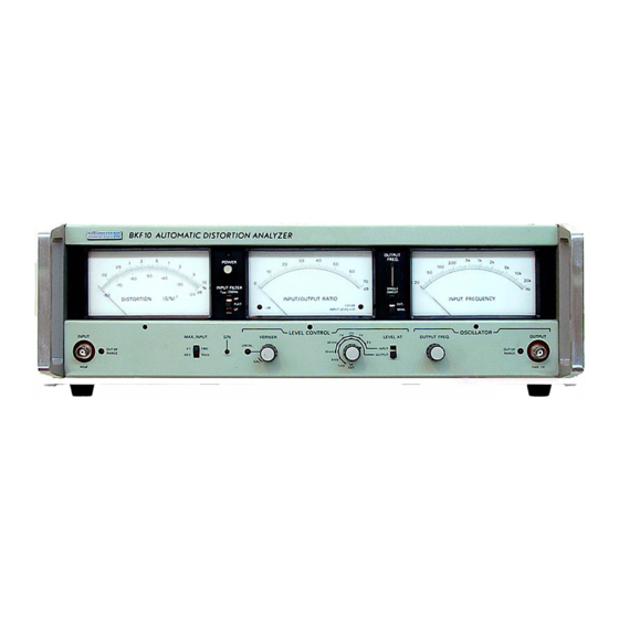
BKF10
automatic distortion analyzer
OPERATING
INSTRUCTIONS
INTRODUCTION
The BKF10 Automatic Distortion Analyzer
provides
fully
automatic
total
distortion and amplitude response measure
ments
with
comprehensive
automatic recording of the measurements,
and external control facilities that enable
it to form a natural part of ·automatic test
systems instrumentation. The BKF10 is in
tended for measurements on Hi-Fi equip
ment, broadcast transmissien lines, audio
studio equipment, etc., and provides facili
ties for measurements in accordance with
the relevant sections of DIN 45,500.
Because of its rather special nature, it is
strongly recommended that these operat
ing instructions are read completely be
fore taking the BKF10 in use.
Instructions are given for the basic operat
ing routine, which is the same whatever
.the application, so that the user will .quick
Iy become familiar with the BKF10 and its
harmonic
facilities.
A short description of the internal function
facilities
for
of the BKF10 is included to assist in un
derstanding the principles of its operation.
All measurements made with the BKF10
can be recorded.
While almost any x-y or x-t recorder may
be used with the BKF10, preference should
be given to the Radiometer REC61S2 Ser
vograph, an x-t recorder fully compatible
with the BKF10,
necessary interface items (interface unit,
interconnecting cable and specially cali
brated recording charts)
cordings with a high degree of accuracy
and resolution.
It is our intention, from time to time, to
issue Application Notes concerning speci
fic applications of Radiometer products .
Please call your nearest Radiometer repre
sentative and have him send you any Ap
plication Notes available for the BKF10.
which includes all the
for making re
COPENHAG EN
Advertisement
Table of Contents

Related Manuals for RADIOMETER BKF10


Summary of Contents for RADIOMETER BKF10
- Page 1 A short description of the internal function ments with comprehensive facilities of the BKF10 is included to assist in un automatic recording of the measurements, derstanding the principles of its operation. and external control facilities that enable All measurements made with the BKF10 it to form a natural part of ·automatic test...
- Page 2 19. Lamp warns when OUTPUT from frequency sweep function. (fully counter-clockwise). BKF10 is too low or too high (1 mV to 1 V). Check settings of MAX. INPUT 8. Oscillator function selector switch. Se 15. VERNIER control for level control switch and LEVEL CONTROL switChl lects SINGLE SWEEP function.
- Page 3 1. To eliminate the effects of hum and 2. Set the controls of the BKF10 as fol INPUT/OUTPUT RATIO MEASUREMENTS Input/output ratios are indicated on the n oise below 250 Hz, set the INPUT lows: linear dB scale of the INPUT/OUTPUT INPUT FILTER: FLAT F ILTER (2) switch to HP.
- Page 4 INPUT FREQUENCY me with LEVEL CONTROL switch (16) ter: +3 V at 20 kHz to 0 V at 20 Hz, 29. Cooling fins. The BKF10 should be set to EXT., input resistance> 1 MQ. 1 V/decade. placed so that adequate ventilation is...
- Page 6 BKF10. The distortion meter section comprises, ment is without a major fault. The built-in AF sweep oscillator has an firstly, a 20 dB switch-selected attenuator extremely low distortion factor «0.Q1%)
- Page 7 " REFERS TO DEVICE UNDER -� TEST OUT PUT FREOU ENCY EXT ..MP LITUDE CONT Fig. 7. Block diagram of BKF10. SPECIFICATIONS Input frequency meter Measuring range: 20 Hz to 20 kHz Distortion meter Accuracy: ±5% Fundamental frequency: 20 Hz to 20 kHz...
Need help?
Do you have a question about the BKF10 and is the answer not in the manual?
Questions and answers