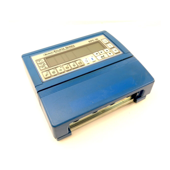
Nordson EPC-30 Instruction Sheet
Pattern control operator panel series epc-30
Hide thumbs
Also See for EPC-30:
- Instruction sheet (10 pages) ,
- Instruction sheet (4 pages) ,
- Instruction sheet (4 pages)
Advertisement
Series EPC-30 Hardware Test Kit
1. Introduction
2. Test Procedure
E 1999 Nordson Corporation
All rights reserved
WARNING: Allow only qualified personnel to perform the
following tasks. Observe and follow the safety instructions in
this document and all other related documentation.
The Series EPC-30 Eclipse pattern control hardware test kit allows you to
quickly determine whether the circuit boards and other hardware in the
main control unit are functioning properly.
Use these procedures to test the Series EPC-30 hardware.
Follow this procedure to connect the test cable or cables. If your unit has
an input/output (I/O) board, you will need to connect two cables.
WARNING: Risk of equipment damage or personal injury.
Disconnect and lock out power to the unit.
1. Turn off power to the unit.
2. Remove the terminal block cover.
3. See Figure 1. Disconnect the quick-disconnect part of terminal
block X7 that is closest to the edge of the main control board and
then disconnect both quick-disconnect parts of X8.
337 158A
Issued 5/99
Instruction Sheet
P/N 337 158A
Manual 66- -EPC30- -IS- -05 (formerly 46-449)
Advertisement
Table of Contents

Summary of Contents for Nordson EPC-30
- Page 1 Observe and follow the safety instructions in this document and all other related documentation. The Series EPC-30 Eclipse pattern control hardware test kit allows you to 1. Introduction quickly determine whether the circuit boards and other hardware in the main control unit are functioning properly.
- Page 2 Series EPC-30 Hardware Test Kit Connecting the Test Cables (contd) 5742124A Fig. 1 Main Control Board Connectors 1. Terminal block X8 4. Red light at DS5 2. Terminal block X7 5. Terminal block X1 on I/O board 3. Header X1 4.
- Page 3 Series EPC-30 Hardware Test Kit Running the Hardware Test Follow this procedure to run the hardware test. 1. Turn on the power to the unit. NOTE: See Figure 2. The hardware test will begin as soon as you turn the unit on. The unit display windows will indicate the test as...
- Page 4 Series EPC-30 Hardware Test Kit Running the Hardware Test 2. See Figure 1. Allow the test to run for at least one minute and examine the red light at position DS5 on the main control board. (contd) 3. If the light is flashing, the unit’s hardware is working properly.
- Page 5 S Test cable, I/O board NOTE A: This cable is required only if your unit has the optional I/O board. Original copyright date 1999. Nordson and the Nordson logo are registered trademarks of Nordson Corporation. 337 158A Manual 66- -EPC30- -IS- -05 (formerly 46-449)
- Page 6 Series EPC-30 Hardware Test Kit Manual 66- -EPC30- -IS- -05 (formerly 46-449) 337 158A E 1999 Nordson Corporation All rights reserved Issued 5/99...


Need help?
Do you have a question about the EPC-30 and is the answer not in the manual?
Questions and answers
패널 EPC-30 구입 요청합니다
The Nordson EPC-30 panel can be purchased from online retailers. One option is Hot Melt Supply Company LLC, where it is listed for sale. You can visit their website, find the product, and add it to your cart for purchase. The price is $1,925.00, and shipping costs are calculated at checkout. Another option may be Radwell, but availability may vary as the product is discontinued by the manufacturer.
This answer is automatically generated