Nordson EPC-30 Instruction Sheet
Current-to-pressure (i/p)
transducer epc-30 series
Hide thumbs
Also See for EPC-30:
- Instruction sheet (6 pages) ,
- Instruction sheet (4 pages) ,
- Instruction sheet (4 pages)
Advertisement
Series EPC-30 Current-to-Pressure (I/P)
Transducer
Introduction
Specifications
Item
Air supply input pressure
Air supply output pressure
Input impedance
Input signal
NOTE A: The transducer was calibrated using a 6.6−6.9 bar (95−100 psi) air supply.
B: With a 6.6−6.9 bar (95−100 psi) air supply, the output should be 0−0.3 bar (0−5 psi) with a 4 mA signal or
6.0−6.4 bar (87−93 psi) with a 20 mA signal.
E 2010 Nordson Corporation
WARNING! Allow only personnel with appropriate training and experience
to operate or service the equipment. The use of untrained or inexperienced
personnel to operate or service the equipment can result in injury, including
death, to themselves and others, and damage to the equipment.
This instruction sheet contains the procedure for installing the
current-to-pressure (I/P) transducer (kit P/N 772033).
If the Eclipset EPC-30 pattern control is equipped with an optional
input/output (I/O) board, the I/P transducer can be installed to provide
run-up control for the system. Refer to the Eclipse EPC-30 pattern control
manual for setting the run-up control.
The following table lists specifications for the I/P transducer.
Specification
8.6 − 10.3 bar (125 − 150 psi)
0.2 − 8.3 bar (1 − 120 psi)
260 ohms (nominal)
4 − 20 mA VDC
Instruction Sheet
P/N 331276B
Note
A
A
B
Part 331276B
02
02
Advertisement
Table of Contents

Related Manuals for Nordson EPC-30


Summary of Contents for Nordson EPC-30
- Page 1 If the Eclipset EPC-30 pattern control is equipped with an optional input/output (I/O) board, the I/P transducer can be installed to provide run-up control for the system. Refer to the Eclipse EPC-30 pattern control manual for setting the run-up control.
-
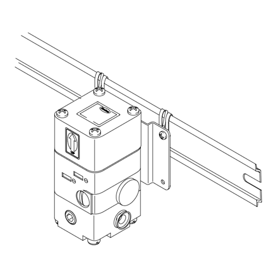
Page 2: I/P Transducer Installation
Series EPC-30 Current-to-Pressure (I/P) Transducer I/P Transducer Installation Use this procedure to install the I/P transducer. CAUTION! Mount the transducer with the UP arrow pointing directly up. Mounting the transducer in any other position will change the current-to-pressure ratio. 1. Use one of the following methods to mount the transducer-and-bracket assembly within 30 feet of the hot melt unit’s pump. - Page 3 5. Set the hot melt unit’s air pressure regulator at the maximum setting (turn the regulator fully clockwise). 6. Route the transducer cable to the Eclipse EPC-30 pattern control. Refer to the Eclipse EPC-30 pattern control manual for instructions on: A.
-
Page 4: Troubleshooting
Series EPC-30 Current-to-Pressure (I/P) Transducer Troubleshooting The following troubleshooting guide allows for a quick check in the field to help reduce down time. For additional troubleshooting information, refer to the manuals provided with the other equipment used in the hot melt system. - Page 5 Series EPC-30 Current-to-Pressure (I/P) Transducer Figure 3 Pneumatic components of the transducer 1. Orifice assembly 5. Spring 9. Body assembly 2. Zero and span protector assembly 6. Spacer 10. In port 3. Strain relief 7. Control diaphragm assembly 11. Gauge port 4.
-
Page 6: Electronic Section
Series EPC-30 Current-to-Pressure (I/P) Transducer Troubleshooting the Pneumatic Section NOTE: If the diaphragm fails, the transducer will leak internally. Problem Possible Cause Corrective Action Supply air on and the signal is set Make sure that the air supply is to 4 mA... - Page 7 Series EPC-30 Current-to-Pressure (I/P) Transducer Figure 4 Electrical components of the transducer 1. Bonnet 4. Circuit board assembly 7. Strain relief 2. Magnet 5. Orifice assembly 8. Gauge port 3. Coil/spring assembly 6. Zero and span protector 9. Housing assembly assembly 10.
-
Page 8: Basic Calibration
Series EPC-30 Current-to-Pressure (I/P) Transducer Troubleshooting the Electronic Section Use a multi-meter with both continuity and resistance to troubleshoot the transducer’s electronic section. Follow the sequence below: 1. Connect the test leads to the black and white leads on the transducer and check for continuity. -
Page 9: Field Troubleshooting
Series EPC-30 Current-to-Pressure (I/P) Transducer SPAN Adjustment The SPAN adjustment potentiometer is located on the front of the transducer. It is used to set the maximum pressure output. The minimum and maximum pressure outputs must be checked each time an adjustment is made. - Page 10 B: The cable and strain relief bushing are preassembled on the transducer. 5742121A Figure 5 Transducer service kit parts Issued 08/10 Original copyright date 1999. Nordson and the Nordson logo are registered trademarks of Nordson Corporation. Part 331276B E 2010 Nordson Corporation...
Need help?
Do you have a question about the EPC-30 and is the answer not in the manual?
Questions and answers