Data Aire dap 4 Installation, Operation & Maintenance Manual
Data alarm processor/control system
Hide thumbs
Also See for dap 4:
- User manual (137 pages) ,
- Supplement manual (28 pages) ,
- Protocol manual (13 pages)

Related Manuals for Data Aire dap 4


Summary of Contents for Data Aire dap 4
- Page 1 4 Installation, Operation & Maintenance Manual Data Aire, Inc. 230 W. BlueRidge Avenue Orange, CA 92865 www.dataaire.com...
- Page 2 Data Aire, Inc. reserves the right to make design changes for the purpose of product improvement or to withdraw any design without notice.
-
Page 3: Table Of Contents
Menu L - Configure I/O ......................47 dap4 Control Logic ........................65 Temperature Sensor Chart ....................100 Terminal Block Wiring Diagram ..................... 101 dap4 Control Board PIN ID ....................102 Manual Bypass Switches ...................... 104 Addendum for the gPod Model ..................... 105 Contact Data Aire ........................110... -
Page 5: Standard Features
The dap4 continues the tradition of advanced electronic devices from Data Aire for monitoring and control of computer room air conditioning units which began in 1977. Each generation has provided more accurate monitoring information and flexibility in controlling the unit. The dap4 offers the definite answer for precision environmental control. The dap4 control system not only controls and monitors temperature, humidity, airflow and cleanliness, it provides component run times, alarm history and an automatic self-test of the microprocessor. All messages are sequentially displayed on a backlit LCD (liquid crystal display). -
Page 6: Operational Features
OPERATIONAL FEATURES (Optional features may require additional components and/or sensors) Sequential Load Activation: Time and temperature based logic that sequentially starts and stops stages of cooling and reheat Compressor Short-Cycle Control: Prevents excessive compressor wear by using restart and anti-cycle limits Automatic or Manual Restart: Restart methods are programmable in the event of a power failure Supplemental Compressor Operation during Energy Saver Mode: Extends the savings from Energy Saver by al- lowing one or two compressors to supplement the cooling as needed when Energy Saver cooling is not sufficient Humidity Anticipation: Modifies the humidity setpoint to reduce excess humidification and dehumidification... -
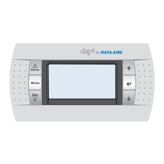
Page 7: Display Panel
DISPLAY PANEL Conditions and Data Displayed TEMPERATURE: Current return air temperature (°F or °C) UNIT TYPE: Data Aire model type DISCHARGE AIR: Current Discharge Air Temp (°F or °C)* DATE: Current date (month/day/year) UNIT ID/ZONE ID: Assigned unit ID and Zone Number* TIME: Current time (hour/minute) TEMPERATURE SETPOINT: Current temp setpoint (°F or °C) -
Page 8: Programmable Selections
PROGRAMMABLE SELECTIONS TEMPERATURE SETPOINT TEMPERATURE DEADBAND HIGH TEMPERATURE ALARM LIMIT LOW TEMPERATURE ALARM LIMIT HUMIDITY SETPOINT HUMIDITY DEADBAND HIGH HUMIDITY ALARM LIMIT LOW HUMIDITY ALARM LIMIT COMPRESSOR LEAD/LAG SEQUENCE RESET EQUIPMENT RUNTIMES AUDIO ALARM MODE HUMIDITY ANTIC PAT ION COMPRESSOR SHORT CYCLE ALARM DEHUMIDIFICATION MODE LOW DISCHARGE TEMPERATURE ALARM LIMIT* POWER RESTART/RESTART MODE... -
Page 9: Getting Started
Getting Started: The dap4 consists of two main components: the control module and the display panel. The control module is located in the electrical panel. The display panel is remotely mounted to one of the outer front doors. The two are connected by special telephone type cable harness (units may be ordered with longer cables for optional remote wall mounting). -
Page 10: Accessing Menus/Passwords
DA gForce 05/19/11 12:08 TSP 72.0 F Hum SP 50% Unit Status: UnitOn Powering the Unit ON/OFF Before powering unit ON, check that power is available and proper connections have been completed Note: The unit is shipped with the control power in the OFF (Off by Key) position Turn the disconnect switch to the ON position. -
Page 11: Service Level Password
The SERVICE LEVEL password allows viewing and changes to the following Menus: A. On/Off B. Setpoint C. Clock/Scheduler D. Input/Output E. Historical Data F. Information G. Network Configuration H. Sensor Calibration I. Manual Control K. Alarms/Limits The FACTORY LEVEL password allows changes to the SERVICE LEVEL Menus plus the follow- ing Menus: J. -
Page 12: Changing The Service Level Password
The controller is based on the unit type, unit components and options. Under normal circumstances these menus should not be changed. If they need to be changed, please consult with Data Aire engineering or service personnel before proceeding. Changing the Service Level Password The Service Level password can be changed by doing the following: Enter the Main Menu by pressing the Menu key. - Page 13 Entering Menu Settings MENU A – ON/OFF MENU A allows the unit power to be switched from ON to OFF and OFF to ON (Service Level password is required for entry). Enter Menu A by pressing the MENU key. Use the UP or DOWN key to scroll through the menus. Press the UP or DOWN key until “A.
-
Page 14: Menu B - Setpoints
MENU B - SETPOINTS MENU B allows viewing and changing of Setpoints (Service Level password is required for entry) Press the UP or DOWN key until “B. Setpoint” appears and is highlighted. Press the ENTER key. Use the UP or DOWN key to scroll through the screens. Menu B has two screens. The following will appear on the first Menu B screen (values are for reference only): Setpoints TEMP SETPOINT... - Page 15 To change the value of any one of the setpoint values, move the cursor by pressing the ENTER key to the desired setpoint. The cursor will flash on the input value. Press the UP or DOWN button to increase or decrease the value. Once the desired setpoint value has been changed, press the ENTER key to move to the next setting or until the cursor is at the top of the screen. Exit the Setpoint Menu by pressing the Esc key. The display screen will return to the MAIN MENU. Use the UP or DOWN Keys to advance to another Menu or press the Esc Key to return to the normal operating mode.
-
Page 16: Menu C - Clock/Scheduler
MENU C – Clock/Scheduler MENU C allows programming for setting night set-back, week-end and special day schedules Menu C should only be used for non-critical applications where units may be cycled off without any damage to sensitive electronic equipment. The typical application is comfort cooling where units may be shut down during non-working hours. - Page 17 If Set-Back enable is YES, the Override Schedule will appear as the following (values are for refer- ence only): Set-Back Settings Set-Back Enable Override Schedule Override Time: 12Hrs Cooling Offset: Heating Offset: Humidify Offset: Dehumidify Offset: To change values, move the cursor to the desired input by pressing the ENTER key. Change the value by pressing either the UP or DOWN key.
- Page 18 The cursor will return to the title block. Repeat the same step for each day to be copied or select ALL. ▼ Press the ENTER key. The cursor will flash on the “NO or YES” setting. Pressing the UP or DOWN key will change from YES to NO or NO to YES. Leave in the NO setting until selections have been made.
- Page 19 The following will be displayed (values are for reference only): Special Day Scheduler Date Schedule SD1: --/-- -------- SD2: --/-- -------- --/-- -------- SD4: --/-- -------- SD5: --/-- -------- SD6: --/-- -------- Available settings: Normal SP Turn Off Set-Back Once the settings are complete, with the cursor in the title block, press the DOWN key to advance to the next screen or press Esc to return to the Main Menu or press the Esc key to return to nor- mal operation.
-
Page 20: Menu D - Input/Output
MENU D – INPUT/OUTPUT MENU D is a view only menu allowing the user to view the various input and outputs. The values are factory set and only if instructed by Data Aire engineering or service personnel should these be changed. - Page 21 ▼ Press the DOWN key to view the next screen. The following will be displayed (values are for reference only): Analog Input Return Air Temp Input B04: 70.8 ▼ Press the DOWN key to view the next screen. The following will be displayed (values are for reference only): Analog Output 3 Fan Speed Output B04: 8.50vdc ▼ Press the DOWN key to view the next screen. The following will be displayed (values are for reference only): Analog Output 4 Optional Output #1 Output...
- Page 22 ▼ Press the DOWN key to view the next screen. The following will be displayed (values are for reference only): Analog Output 5 Optional Output #2 Output 0.00vdc All screens have been viewed. BY pressing the UP or DOWN keys, the screens can be viewed. ▼ Press the MENU key to return to the main menu. Choose another menu by pressing the UP or DOWN keys or press ESC to return the main menu. 22 • dap4 User Manual...
-
Page 23: Menu E - Historical Data
MENU E – Historical Data MENU E allows viewing alarms, component runtimes and resetting of component runtimes. The first screen will display (if any) alarm history ▼ Press the ENTER key to view The following will be displayed (inputs are for reference only): Time and Date of Alarm Alarm Type Humidity at time of occurrence Chilled Water temperature at time of occurrence (if applicable) Discharge Air Temperature at time of occurrence (if applicable) 11:13:10... - Page 24 ▼ Press the ENTER key until the cursor is flashing on the title line. Press the DOWN key to move to next screen. The screen will display the following: Run Hours 2 Reset$ Htr 1: 00000 Htr 2: 00000 Htr 3: 00000 Humidity: 00000 Dehum:: 00000 ▼ Press the ENTER key to move the cursor. The cursor will flash the reset choice of No or Yes. To reset and clear runtimes, press the UP or DOWN key. ▼ Press the ENTER key until the cursor is flashing on the title line. Press the DOWN key to move to next screen. The screen will display the following: Run Hours 3 Reset$ Engy Svr:...
-
Page 25: Menu F - Information
MENU F allows viewing of the processor version (Service Level password is required for entry). This is a view only menu. Once password has been entered scroll until Menu F – Information is highlighted. Press the ENTER key to view. There two screens. The first screen will display the following: Information Data Aire Inc. Code: Ver: 1.0B01 05/04/11 Manual code: 4.30 12/22/08... -
Page 26: Menu G - Network Config
MENU G – NETWORK CONFIG MENU G allows selection of BMS protocol. (Service Level password is required for entry) Once password has been entered, press the UP or DOWN key until “G. Network Config” appears and is highlighted. Press the ENTER key. The following will be displayed (values are for reference only): Bms Configuration BMS Port 1 Protocol: MODBUS Only the protocol can be changed. -
Page 27: Menu H - Calibrate Sensors
MENU H allows calibration of the unit installed sensors. (Service Level password is required for entry). Return air temperature and humidity sensors are standard with Data Aire units. Dependent on options and equipment type, a discharge air and chilled water sensor may be installed in the unit. - Page 28 The following will be displayed (values are for reference only): Analog Input Discharge Air Sensor Input B09 Offset xx.x Value xx.x ▼ Press the ENTER key to move the cursor. The cursor will flash at the Offset. By pressing the UP (to increase) or DOWN (to decrease) keys the Offset can be changed. Once the change has been made, press the ENTER key and the cursor will move to the upper portion of the screen.
-
Page 29: Menu I - Manual Control
MENU I – MANUAL CONTROL MENU I allows manually running different unit components (Service Level password is required for entry). In the Main Menu screen press the UP or DOWN key until “I. Manual Control” appears and is high- lighted. Press the ENTER key. The following will be displayed (values are for reference only): Manual Output Mgmt: 1 Return to Auto:... - Page 30 Move the cursor to the title block by pressing the ENTER key. To return to the Main Menu press the Esc key or to view the following screen press the DOWN key. The following will be displayed (values are for reference only): Analog Output 3 Fan Speed Mode: Auto...
-
Page 31: Menu J - Factory Setting
IMPORTANT NOTE: MENU J is for setting the control to the type equipment and options ordered. This requires the Factory Level password and entry should be limited to Data Aire factory and service personnel. Consult with factory before making any changes to these factory settings. - Page 32 CW Mode: There are nine (9) modes: Const. Speed, BMS Speed, Vlv. Pos. Speed, Air Pres- sure, Const. Flow, BMS Flow, Vlv. Pos. Flow, Mod to R. Air, and Mod to Rack CW Speed: The range is 60 to 100% Disch Temp Is Required DX Mode: There are six (6) modes: Const. Speed, BMS Speed, Air Pressure, Const. Flow,...
- Page 33 Fan Air Flow Fans Installed: ▼ Press the DOWN key to view the next screen: Once a selection or selections have been made, move the cursor to the title block by pressing the ENTER key ▼ Press the DOWN key to view the next screen: The following will be displayed (inputs are for reference only) Compressor Settings Type: Dual Pri w/ UnLdr Control: Return Temp Electronic Valve: Dual HP Lockout: None...
- Page 34 EEV – Electronic Expansion Valve When unit has electronic expansion valve the following screen will be displayed (values are for reference only): Setpoints Temp Setpoint: 72°F Temp Deadband 2°F Stage-to-stage: 0.3°F Superheat: 6.0°F Compressor Settings Type: Dual Primary Control: Return Temp Electronic Valve: Dual HP Lockout: None Delay btw stages: NOTE: This screen only appears when the “Electronic Valve” is selected as “One” or “Two” in Menu J - Factory Setting - Compressor Settings screen.
- Page 35 Press the DOWN key to view the next screen: The following will be displayed (inputs are for reference only): Reheat Settings Reheat Stages: 3-Elect Lead Reheat: First Enable SCR Y4: Band: 1°F Available Selections: One, two, three, 1-Elect, 3-Elect, or none If two or three are selected, the display module will display “Lead Reheat:” By pressing the UP or DOWN key the lead choices (First, Second or Third) can be seen.
- Page 36 Available Selections: Wtr Vlv (Water Valve): Engy Svg Cool Chilled Wtr Cool Chilled Wtr Reg Aux Chill Wtr None Note: If None is selected, Wtr Vlv Voltage, Wtr Vlv Action and Engy Lockout Time will appear on the display module screen. E-Saver Assist: None 1 Comp* 2 Comp* 4 Comp*...
- Page 37 Control: P + 1 Notes: If selecting PID, the Band, Integration Time, Derivative Time and Output Period will appear on the screen and values can be entered. If selecting P + 1, the Band, Integration Time and Output Period will appear on the screen and values can be entered.
- Page 38 Dehum Mode: None 1C In Limit (1 compressor & within reheat limits) 2C In Limit (2 compressors & within reheat limits) 1C No Limit (1 compressor & no reheat limits) 2C No Limit (2 compressors & no reheat limits) Once a selection or selections have been made, move the cursor to the title block by pressing the ENTER key or press the Esc key to return normal operating mode Press the DOWN key to view the next screen: The following will be displayed (input is for reference only):...
-
Page 39: Menu K - Alarms And Limits
MENU K – ALARMS and LIMITS MENU K is for setting the control alarms and limits. (Service Level password required and entry should be limited to service personnel starting or servicing the equipment). In the Main Menu screen press the UP or DOWN key until “K. Alarms & Limits” appears and is highlighted. - Page 40 Available Selections: Comp Short Cycle: Yes or No Water Alarm Action: Alarm Only Shutdown Unit Lockout Comps Reset Alarm Log: Yes or No Alarm Screen Contact: No Contact Message Service Company Maint Engineer Data Proc Mngr Custom Message (factory installed) Once a selection or selections have been made, move the cursor to the title block by pressing the ENTER key ▼ Press the DOWN key to view the next screen:...
- Page 41 ▼ Press the DOWN key to view the next screen: The following will be displayed (values are for reference only): Return Air Alarms Firestat Setpoint: Hi Temp Alarm: Set Point: Lo Temp Alarm: Set Point: Available Selections: Firestat Setpoint: The range is 100 to 150°F (factory setting is 150°F) Hi Temp Alarm: Yes or No (factory setting is Yes) Set Point:...
- Page 42 Discharge Alarm Lo Disch T Alarm: Set Point: The Set Point range is 45 to 60°F (factory setting is 52°F) Once a selection or selections have been made, move the cursor to the title block by pressing the ENTER key ▼ Press the DOWN key to view the next screen: The following will be displayed (values are for reference only): Humidity Alarms...
- Page 43 Alarm Inputs Custom Alarm Messages Alarm #1 (DI-13) SEE TAG INSIDE DOOR Alarm #2 (DI-14) SEE TAG INSIDE DOOR Available Selections: Alarm #1: SEE TAG INSIDE DOOR Custom Message FAN MOTOR OVERLOAD CHK HUMIDIFIER CYL STANDBY PUMP ON UPS ON-CHK MAIN POWER UNIT IN STBY REHEAT &...
- Page 44 Available Selections: Alarm #3: SEE TAG INSIDE DOOR Custom Message FAN MOTOR OVERLOAD CHK HUMIDIFIER CYL STANDBY PUMP ON UPS ON-CHK MAIN POWER UNIT IN STBY REHEAT & HUM INHIBIT HUMIDIFIER INHIBITED REHEAT INHIBITED Alarm #4: SEE TAG INSIDE DOOR Custom Message FAN MOTOR OVERLOAD CHK HUMIDIFIER CYL...
- Page 45 Alarm Output Function 2 - See sample screen shot at end of section Alarm 1 Alarm 2 Alarm 3 Alarm 4 C1 Hi Pr Yes or No Yes or No Yes or No Yes or No C1 Low Pr Yes or No Yes or No Yes or No Yes or No...
- Page 46 ▼ Press the DOWN key to view the next screen: The following will be displayed (values are for reference only): Alarm Output Function 5 - See sample screen shot at end of section Alarm 1 Alarm 2 Alarm 3 Alarm 4 Heat Inhbt Yes or No Yes or No Yes or No Yes or No Filter...
-
Page 47: Menu L - Configure I/O
MENU L - Configure I/O (factory use only) Menu L is a factory for configuring the unit’s digital inputs and the unit’s analog inputs and outputs. This requires the Factory Level password and entry should be limited to Data Aire factory and service personnel. ▼ Press the UP or DOWN key until “L. Configure I/O” appears and is highlighted. Press the ENTER key. The following will be displayed (values are for reference only):... - Page 48 The following can be changed by pressing the DOWN key: Channel – Open or Closed Delay – the range is 0 – 999 seconds Status – Open or Closed Once a selection or selections have been made, move the cursor to the title block by pressing the ENTER key Press the DOWN key to view the next screen: The following will be displayed (values are for reference only):...
- Page 49 Channel – Open or Closed Delay – the range is 0 – 999 seconds Status – Open or Closed (Status can’t be changed.) Once a selection or selections have been made, move the cursor to the title block by pressing the ENTER key ▼ Press the DOWN key to view the next screen: The following will be displayed (values are for reference only):...
- Page 50 Channel – Open or Closed Delay – the range is 0 – 999 seconds Status – Open or Closed (Status can’t be changed.) Once a selection or selections have been made, move the cursor to the title block by pressing the ENTER key ▼ Press the DOWN key to view the next screen: The following will be displayed (values are for reference only):...
- Page 51 Once a selection or selections have been made, move the cursor to the title block by pressing the ENTER key ▼ Press the DOWN key to view the next screen: The following will be displayed (values are for reference only): Digital Input HUMIDIFIER FAULT SW Channel Action: Closed Delay: Status: Open Move the cursor by pressing the ENTER key.
- Page 52 ▼ Press the DOWN key to view the next screen: The following will be displayed (values are for reference only): Digital Input HI CONDENSATE SW Channel ID11 Action: Closed Delay: Status: Closed Move the cursor by pressing the ENTER key. Move the cursor to change the setting. The following can be changed by pressing the DOWN key: Channel –...
- Page 53 The following will be displayed (values are for reference only): Digital Input OPT ALARM #1 SWITCH Channel ID13 Action: Closed Delay: Status: Open Move the cursor by pressing the ENTER key. Move the cursor to change the setting. The following can be changed by pressing the DOWN key: Channel –...
- Page 54 The following will be displayed (values are for reference only): Digital Input OPT ALARM #3 SWITCH Channel ID15 Action: Closed Delay: Status: Open Move the cursor by pressing the ENTER key. Move the cursor to change the setting. The following can be changed by pressing the DOWN key: Channel –...
- Page 55 The following will be displayed (values are for reference only): Digital Input FLOOR WATER SWITCH Channel ID17 Action: Closed Delay: Status: Open Move the cursor by pressing the ENTER key. Move the cursor to change the setting. The following can be changed by pressing the DOWN key: Channel –...
- Page 56 The following will be displayed (values are for reference only): Analog Input Humidity Sensor Enable: ON Channel: B1 Normal 4-20mA Minimum: Maximum: 100.00 Offset: Value: 35.6 Move the cursor by pressing the ENTER key. Move the cursor to change the setting. The following can be changed by pressing the DOWN key: Enable –...
- Page 57 ▼ Press the DOWN key to view the next screen: The following will be displayed (values are for reference only): Analog Input Static Air Pressure Enable: Off Channel: B7 Note: If (Enable) OFF is selected the Normal, Minimum, Maximum, Offset and Value will not be displayed. With Enable ON, Normal, Minimum, Maximum, Offset and Value will be displayed and values changed. Once a selection or selections have been made, move the cursor to the title block by pressing the ENTER key ▼ Press the DOWN key to view the next screen: The following will be displayed (values are for reference only):...
- Page 58 The following will be displayed (values are for reference only): Analog Input Chilled Water Sensor Enable: On Channel: B10 High Res. Offset: Value: 74.1 Note: If (Enable) OFF is selected the High Res, Offset and Value will not be displayed. With Enable ON, High Res., Offset and Value will be displayed and values changed.
- Page 59 The “Choose Name” allows one of the following to be selected by moving the cursor to the Choose Name and pressing the UP or DOWN key: Diff Pressure Suct Pressure Disch Pressure Outside Hum Outside Temp Zone Humidity Zone Air Temp CW Flow Cond Wtr Flow Ret Air Temp Sply Air Temp CW Ret Temp...
- Page 60 ▼ Press the DOWN key to view the next screen: The following will be displayed (values are for reference only): Optional Sensor #3 Enable: OFF Choose Name With Enable OFF Optional Sensor #3 Enable: OFF Choose Name Normal Offset: Value: -2.1 With Enable ON The “Choose Name” allows one of the following to be selected by moving the cursor to the Choose Name and pressing the UP or DOWN key: Diff Pressure Suct Pressure...
- Page 61 Optional Sensor #4 Enable: OFF Choose Name Normal Offset Value: -2.1 With Enable OFF With Enable ON The “Choose Name” allows one of the following to be selected by moving the cursor to the Choose Name and pressing the UP or DOWN key: Diff Pressure Suct Pressure Disch Pressure Outside Hum...
- Page 62 Once a selection or selections have been made, move the cursor to the title block by pressing the ENTER key ▼ Press the DOWN key to view the next screen: The following will be displayed (values are for reference only): Analog Output Config Channel: Action: DIRECT Minimum 0.0vdc Maximum: 0.0vdc Move the cursor by pressing the ENTER key.
- Page 63 The following can be changed by pressing the DOWN key: Channel – there are six (6) selections (Y1, Y2, Y3, Y4, Y5 and Y6). There are five Analog outputs available. DO NOT ASSIGN THE SAME CHANNEL ON MORE THAN ONE ANA- LOG OUTPUT. Action: there are two choices; DIRECT AND REVERSE Minimum: the range is from 0.0vdc to 10.0vdc Maximum: the range is from 0.0vdc to 10.0vdc Once a selection or selections have been made, move the cursor to the title block by pressing the ENTER key...
- Page 64 The following will be displayed (values are for reference only): Analog Output Config Channel: Action: DIRECT Minimum 0.0vdc Maximum: 0.0vdc Move the cursor by pressing the ENTER key. Move the cursor to change the setting. The following can be changed by pressing the DOWN key: Channel – there are six (6) selections (Y1, Y2, Y3, Y4, Y5 and Y6). There are five Analog outputs available.
-
Page 65: Dap4 Control Logic
dap4 CONTROL LOGIC SYSTEM START DELAY After the self-test is complete, the Timed Start Delay will be displayed and will start counting down from the programmed delay time. The factory setting is five (5) seconds. The setting is pro- grammed in Menu A – ON/OFF. The range is from 1 to 600 seconds in 5 second increments. BLOWER Plug Fans –... - Page 66 Compressor “OFF” sequence (Decreasing Temperature) Cool 4 OFF at Temperature Setpoint + 3y°F Cool 3 OFF at Temperature Setpoint + 2y°F Cool 2 OFF at Temperature Setpoint + y°F Cool 1 OFF at Temperature Setpoint Note: y = “stage to stage” which can be changed in MenuB-Setpoints; default value is 0.3 5.
- Page 67 Current Temperature = Setpoint + 0.7°F = 70% Position Open Current Temperature = Setpoint + 0.6°F = 60% Position Open Current Temperature = Setpoint + 0.5°F = 50% Position Open Current Temperature = Setpoint + 0.4°F = 40% Position Open Current Temperature = Setpoint + 0.3°F = 30% Position Open Current Temperature = Setpoint + 0.2°F =...
- Page 68 Current Temperature = Setpoint + Deadband + 0.6°F = 60% Position Open Current Temperature = Setpoint + Deadband + 0.7°F = 70% Position Open Current Temperature = Setpoint + Deadband + 0.8°F = 80% Position Open Current Temperature = Setpoint + Deadband + 0.9°F = 90% Position Open Current Temperature = Setpoint + Deadband + 1.0°F = 100% Position Open 7.
- Page 69 Cool 4 OFF at Temperature Setpoint + 2.2°F and Valve 100% Open Cool 3 OFF at Temperature Setpoint + 1.9°F and Valve 100% Open Cool 2 OFF at Temperature Setpoint + 1.6°F and Valve 100% Open Cool 1 OFF at Temperature Setpoint + 1.3°F and Valve 100% Open until next adjustment period REHEAT 1. There is a one (1) minute delay between the stop of any reheat stage to the start of any reheat stage.
- Page 70 SCR REHEAT SETTING 1. If unit is built with an optional SCR reheat, Menu F- Factory Settings - Reheat setting - Enable Reheat SCR Y4 is set to YES, dap4 will send a 0-10VDC modulating signal to control a SCR reheat controller.
- Page 71 4. The humidification staging sequence of each adjustment period for ON/OFF of non-modulating humidifiers is as follows: Humidifier is ON at Humidity Setpoint – Humidity Deadband Humidifier is OFF at Humidity Setpoint – 1.0% 5. The humidification staging sequence for a modulating humidifier is as follows: Valve is OPENED at Humidity Setpoint – 1.0% Valve is CLOSED at Humidity Setpoint – 0.5% 6. When the humidifier valve is opened, its position will follow a linear ramp that goes from 25% open with the humidity at setpoint minus 0.5% to 100% open at setpoint minus humidity dead- band. DEHUMIDIFICATION 1. Dehumidification Mode can be programmed with one or two compressors for dehumidification and with or without reheat limits (See Menu J –...
- Page 72 Cool 4 ON at Humidity Setpoint + Humidity Deadband + 3% Cool 4 OFF at Humidity Setpoint + 3% Cool 3 OFF at Humidity Setpoint + 2% Cool 2 OFF at Humidity Setpoint + 1% Cool 1 OFF at Humidity Setpoint 8. The sequence for dehumidification with Energy Saver or Auxiliary Chilled Water Cooling is as follows: Valve is OPENED to 100% at Humidity Setpoint + Humidity Deadband...
- Page 73 In DX mode, 2-cooling stages off as follows: Cooling 2 off when dewpoint = High Dewpoint Setpoint - High Dewpoint DB - 0.0°F AND Humidity Setpoint - Humidity Deadband - 0% Cooling 1 off when dewpoint = High Dewpoint Setpoint - High Dewpoint DB - 0.2°F AND Humidity Setpoint - Humidity Deadband - 1% In DX mode, 4-cooling stages on as follows: Cooling 1 on when dewpoint = High Dewpoint Setpoint- 0.6°F OR Humidity Setpoint - 3%...
- Page 74 Open 20% if return_relative_humidity = humidity_setpoint – 0.8% Open 30% if return_relative_humidity = humidity_setpoint – 0.7% Open 40% if return_relative_humidity = humidity_setpoint – 0.6% Open 50% if return_relative_humidity = humidity_setpoint – 0.5% Open 60% if return_relative_humidity = humidity_setpoint – 0.4% Open 70% if return_relative_humidity = humidity_setpoint – 0.3% Open 80% if return_relative_humidity = humidity_setpoint – 0.2% Open 90% if return_relative_humidity = humidity_setpoint – 0.1% Open 100% if return_relative_humidity = humidity_setpoint Chilled Water valve closing While still in dehumidification mode, Chilled Water valve will start to close if dewpoint is de- creasing OR relative humidity is decreasing closer to the setpoints minus deadband. The modulation of the CW valve will be based on whichever has HIGHER demand for CW valve to open. For example, if dewpoint requires the CW valve to open 20% and humidity requires the CW valve to open 50%, as a result, CW valve will open 50%.
- Page 75 Alarms System with Variable Speed Compressor Data Aire gForce Ultra DX series unit can be equipped with a variable speed compressor or a combination of a variable speed compressor and a fixed speed scroll compressor. In these types of unit, Dap4 controller will modulate the VFD of the variable speed compressor using a 0-10VDC signal to maintain either return air temperature setpoint or supply (discharge) air temperature set- point.
- Page 76 When return air temperature = Temperature setpoint + temperature deadband variable speed compressor starts and ramp up to maximum speed. For instance: SP = 72, DB = 2. Compressor will be on at 74°. Variable speed compressor will then use PI (Proportional and Intergral) control algorithm to main the setpoint. Proportional band is the same as deadband. The Intergral band is programmed in Factory settings menu.
- Page 77 For instance: SP = 72, DB = 2, STS = 0.3. Compressor will be on at 74.3 deg. Return air temperature is dropping (Off cycle): Fixed speed compressor C2 turns off when return air temperature drops below temperature setpoint – STS band (default STS band=0.3 deg F) for duration of C2 off delay (default =5s).
- Page 78 Current Temperature = Setpoint + Deadband + 0.0ºF = 0% Position Current Temperature = Setpoint + Deadband + 0.1ºF = 10% Position Current Temperature = Setpoint + Deadband + 0.2ºF = 20% Position Current Temperature = Setpoint + Deadband + 0.3ºF = 30% Position Current Temperature = Setpoint + Deadband + 0.4ºF = 40% Position Current Temperature = Setpoint + Deadband + 0.5F = 50% Position...
- Page 79 The Energy Saver/Auxiliary Chilled Water Cooling logic will be the same and compressor rules for short-cycle time will not be violated. Low discharge temperature alarm limit must be set in menu K-Alarms & Limits. If Discharge temperature drops below this limit, compressors will be inhibited for at least 15 minutes and discharge temperature rises above this limit. If discharge temperature drops below the limit while the variable speed compressor finishing its minimum runtime the CW should close until discharge temperature rises above the limit.
- Page 80 If variable speed compressor C1 runs at the minimum speed for a period of time, it will automatically ramp up to the maximum speed for one minute to maintain the minimum compressor oil level. The temperature may drop slightly during this override period. Compressor cycles on and modulate as follows: Discharge air temperature is rising (On cycle): When discharge air temperature rises to temperature setpoint + temperature DB (deadband), variable speed compressor C1 will start and operate at its minimum speed.
- Page 81 Once fixed compressor C2 started, the variable speed compressor C1 will operate at minimum speed for duration of Delay Modulation. Delay modulation is programmed in Compressor/factory settings menu. Discharge air temperature is dropping (Off cycle): Fixed speed compressor C2 turns off when discharge air temperature drops to the temperature setpoint – C2 offset. Variable speed compressor C1 turns off when discharge air temperature drops to temperature setpoint –...
- Page 82 The Energy Saver/Auxiliary Chilled Water Cooling logic will be the same as the chilled water cooling logic of the discharge air temperature control, this means dap4 uses a preset PID loop to control the CW valve to maintain a discharge air temperature setpoint. Low discharge temperature alarm limit must be set in menu K-Alarms & Limits. If Discharge temperature drops below this limit, compressors will be inhibited for at least 15 minutes and discharge temperature rises above this limit.
- Page 83 If dehumidification is programmed for “1C in limit” or “2C in limit” the dehumidification cooling will be inhibited by reheat if the return air temperature drops below Temperature Setpoint - Temperature DB - 2deg F. Dehumidification will be inhibited until the return air temperature rises above the Temperature Setpoint. Compressor short-cycle time will not be violated. If dehumidification is programmed for “1C No Limit” or “2C No Limit”, dehumidification remains on until the humidity setpoint is reached. In this mode, dehumidification has priority and overcooling is disregarded. The reheat sequence will remain the same. There is a one (1) minute delay between stop-to-start of dehumidification cooling.
- Page 84 Dehumidification cycles on If unit is not in cooling mode, C1 variable speed compressor turns on when humidity is at Humidity Setpoint + Humidity Deadband then runs at its minimum speed (0V). C1 compressor will modulate from 0% to 100% in 0.1% RH increment (10% speed for each 0.1% RH).
- Page 85 If unit is in cooling mode during dehumidification cycle and dehumidification mode is set to “1C in limit”, the cooling control (By temperature setpoint) will override the dewpoint control. If dehumidification mode is set to “1C No Limit”, unit will continue to finish the dewpoint control cycle then reverse to the cooling control. Dehumidification cycles off - Dewpoint is dropping Variable speed compressor C1 starts to ramp down in 0.1 % decrement when dewpoint drops to high dewpoint Setpoint – high dewpoint deadband. Compressor will run at minimum speed (0V) when dewpoint is at high dewpoint setpoint –...
- Page 86 High Relative humidity Limit in dewpoint control • If high relative humidity condition occurs while humidity control mode is set to Dewpoint control then dewpoint control has priority over the relative humidity control. • If high dewpoint setpoint satisfies but relative humidity rises to relative humidity setpoint, the dehumidification control will be as follows: Single Variable speed compressor system Dehumidification cycles on: If unit is not in cooling mode, the variable speed compressor turns on when humidity is at Humidity Setpoint (HSP) -1%.Compressor will modulate from 0% to 100%, 10% speed for every 0.1%RH.
- Page 87 Alarm relay energizes when this alarm is active. Optional compressor lock-out on high suction temperature alarm can be enable in menu K- alarm and limits of dap4. The default setting is “disable”. If enable, when alarm counts match the programmed Lock-out times the compressor will be locked out until it is manually reset by pressing the alarm button while alarm message appears on screen.
- Page 88 AUTOMATIC FLUSH CYCLE for CHILLED WATER or HOT WATER COILS If 100 hours elapses and the chilled water or hot water valve has not opened for normal cooling or heating, the valve will automatically open for 30 seconds to flush the coil. The display module will not display a message indicating the flush cycle is in progress. HUMIDIFIER AUTO-FLUSH TIMER CONTROL 1. Humidifier auto-flush timer is optional. The auto-flush timer is only available on units with infra- red humidifiers. 2. The auto-flush timer is programmable (See Menu J – Factory Settings). 3. The auto-flush cycle takes 11 minutes. The sequence is as follows: • For the first four minutes the drain solenoid is opened and humidification is inhibited (the display module will have the following message: Humidification Inhibited by Auto-Flush).
- Page 89 COMPRESSOR SHORT-CYCLE ALARM 1. Compressor shot-cycle alarm is programmable (See Menu K – Alarms and Limits). A compres- sor short-cycle alarm will activate if the compressor has been energized ten (10) times in a one (1) hour period. 2. The alarm is a warning only. Compressor operation will continue. 3. One cycle is a combination of compressor starts for cooling or dehumidification functions.
- Page 90 NO AIRFLOW ALARM 1. When no airflow is detected via the air flow switch or current sensing relay, the cooling, re- heat, humidification and dehumidification functions are locked out until the alarm condition is corrected. Menu K – Alarms and Limits, allows adjustment of the alarm delay from 5 to 180 seconds in 5 second increments. Adjustment is to minimize false alarms due to air turbulence. 2. On chilled water units a “FAN FAILURE” alarm is included in addition the NO AIRFLOW ALARM.
- Page 91 played on the display module. 3. The audio alarm is a warning only and will not prevent any of the unit functions form operating. 4. The alarm will remain until the alarm condition is corrected. HIGH HUMIDITY ALARM LIMIT 1. The high humidity alarm limit is programmable (See Menu K – Alarms and Limits). The range is from 35 to 90%.
- Page 92 3. The alarm will remain until the alarm condition is corrected. HIGH PRESSURE/INTERNAL OVERLOAD COMPRESSOR ALARM 1. In the event of a high pressure condition, the high head pressure switch is tripped or the compressor(s) overload contact opens, the audio alarm is activated and a “Circuit #1: High Pressure”...
- Page 93 4. The alarm will prevent the unit from operating until the alarm condition is corrected (condensate pump is checked and its float switch is open). FAN MOTOR OVERLOAD ALARM 1. The fan motor overload is optional and requires a motor overload relay contact for each motor. 2. The alarm is programmable (See Menu …….) 3.
- Page 94 STANDBY PUMP ON ALARM 1. The standby pump on alarm is optional and requires a contact from the optional Pump Auto- Changeover control to be added to the remote dry cooler. 2. The alarm is programmable (See Menu K – Alarms and Limits). 3.
- Page 95 5. The alarm will remain until the alarm condition is corrected. REHEAT AND HUMIDIFICATION INHIBITED ALARM 1. The humidification inhibited alarm is optional and requires an input contact from a field supplied contact. 2. The alarm is programmable (See Menu K – Alarms and Limits). 3. The audio alarm is activated and a “Reheat and Humidification Inhibited” message will be dis- played on the display module. 4. If in operating mode, the reheat and humidification is shut off and locked (off) when alarm is present. 5. The alarm will remain until the alarm condition is corrected. CUSTOM MESSAGE ALARM 1.
- Page 96 WARNING: IF CUSTOMER DECIDES TO USE THIS FAN SPEED CONTROL MODE (FAN SPEED CONTROLLED BY BMS), DATA AIRE WILL NOT BE RESPONSIBLE FOR ANY EF- FECTS, MALFUNCTIONS OR SPACE CONTROL CONDITIONS CAUSED BY THIS SELECTION. 3. Speed Proportional to CW Valve (Vlv. Pos. Speed)
- Page 97 The airflow will automatically increase to the maximum airflow set in Maximum Flow when reheat or humidification is required. The airflow will revert to the BMS controlled airflow setting when the unit stops calling for reheat or humidification. WARNING: IF CUSTOMER DECIDES TO USE THIS FAN SPEED CONTROL MODE (AIR FLOW CONTROLLED BY BMS), DATA AIRE WILL NOT BE RESPONSIBLE FOR ANY EFFECTS, MALFUNCTIONS OR SPACE CONTROL CONDITIONS CAUSED BY THIS SELECTION. 7. Airflow Proportional to CW Valve (Vlv. Pos. Flow) - Optional On units where proportional fan airflow control based on the CW valve position is required, the maximum airflow is programmed via Maximum Flow menu, and the minimum airflow as a per- centage of the maximum airflow is programmed via Minimum Flow menu in Fan Air flow setting.
- Page 98 The constant speed is controlled by out putting a constant voltage to the fan speed controller. The fan speed will automatically increase to the maximum fan speed set in MODULATE MAX menu when reheat or humidification is required. The fan speed will revert to the BMS con- trolled fan speed setting when the unit stops calling for reheat or humidification. WARNING: IF CUSTOMER DECIDES TO USE THIS FAN SPEED CONTROL MODE (FAN SPEED CONTROLLED BY BMS), DATA AIRE WILL NOT BE RESPONSIBLE FOR ANY EFFECTS, MALFUNCTIONS OR SPACE CONTROL CONDITIONS CAUSED BY THIS SELECTION. 98 • dap4 User Manual...
- Page 99 The airflow will automatically increase to the maximum airflow set in Maximum Flow when reheat or humidification is required. The airflow will revert to the BMS controlled airflow setting when the unit stops calling for reheat or humidification WARNING: IF CUSTOMER DECIDES TO USE THIS FAN SPEED CONTROL MODE (AIRFLOW CONTROLLED BY BMS), DATA AIRE WILL NOT BE RESPONSIBLE FOR ANY EFFECTS, MALFUNCTIONS OR SPACE CONTROL CONDITIONS CAUSED BY THIS SELECTION. 6. Mod to Rack See RackSense 32 User’s Manual for details.
-
Page 100: Temperature Sensor Chart
TEMPERATURE SENSOR CHART Resistance Resistance Resistance Temperature Temperature Temperature Value Value Value °F °C KΩ °F °C KΩ °F °C KΩ -58.0 -50.0 329.20 33.8 26.13 132.8 56.0 3.42 -56.2 -49.0 310.70 35.6 25.03 134.6 57.0 3.31 -54.4 -48.0 293.30 37.4 23.99 136.4... - Page 101 101 • dap4 User Manual...
- Page 102 Power Inputs I/O Board Pin ID ID Connector Number Unit TB Isolated 24 VAC J1-1 TB3-1 Isolated 24 VAC Common J1-2 TB3-2 Isolated 24 VAC J4-1 TB3-1 Isolated 24 VAC Common J4-2 TB3-2 Control 24 VAC C1, C4, C9, C16 J12-1, J13-1, J16-1 TB1-2B J22-1...
- Page 103 dap4 I/O Control Board and Unit Terminal Block Pin ID Number Control & Alarms – Digital Outputs I/O Board Pin ID ID Connector Number Unit TB System Blower J12-2 TB1-4 Compressor 1 J12-3 TB1-5 Compressor 2 J12-4 TB1-6 Opt Cooling 3rd Stage J13-2 TB2-37 Opt Cooling 4th Stage...
- Page 104 Manual Override Switches For testing and during start-up each Data Aire gForce unit is provided with manual override slide switches. There are seven slide switches. One for each of the following functions: Water Valve Fan Speed Humidifier Heat 1 Cool 2...
- Page 105 Addendum for Dap4 User Manual – gPod Model The gPod model is specifically suited for agricultural applications. It has additional features of Lighting control, CO level control, and Night time temperature and humidity offsets which are explained in this document. Two additional sensors can be installed. sensor: Carel (DPWL417000) 4-20mA. With a 24VDC power supply. Light sensor: 24VAC EM photocell sensor (EM-24A2) Dap4 I/O connections for gPod system 105 • dap4 User Manual...
- Page 106 The dap4 is set to the gPod model at the factory and “gPOD” will appear on the main screen of dap4. Please contact the Data Aire if your dap4 controller is not set to the gPod model as required.
- Page 107 Set point Set point: 1000ppm (100-5000ppm) Dead band: 25ppm (25-1000ppm) Min Valve On: 5s (0-32767s) Valve PWM: 10% (0-100%) Note: This CO set point screen is not shown if the control is not set for CO control in the factory settings menu. Temperature and humidity set point offsets for night time schedule.
- Page 108 Note: Please do not enable any options that are not installed in the unit. high and Low level alarm limit settings To access the CO high and low level alarm set points, press Menu button and enter service password (default is 0000). After entering the password advance to Menu-K “Alarms and Limits”...
- Page 109 Night time mode The night mode can be activated by either; an optional light sensor input or by a programmed time schedule. While in the night mode, the temperature and humidity set points will be offset by the amount of their offset band settings. See section 3c for details. iii) A “Night Sch”...
-
Page 110: Contact Data Aire
CONTACT DATA AIRE Address: Data Aire, Inc. 230 West Blueridge Avenue Orange, CA 92865 Telephone: 714-921-6000 800-347-AIRE (2473) Toll Free E-mail: Service@dataaire.com Engineering@dataaire.com Sales@dataaire.com Fax: 714-921-6010 Main 714-921-6011 Engineering 714-921-6022 Parts Sales Web Site: www.dataaire.com Job/Unit Information: Data Aire Job Number: __________________________ Serial Number: ________________________________ Model Number: ________________________________... - Page 111 111 • dap4 User Manual...
- Page 112 230 W. BlueRidge Ave. Orange, CA 92865 800-347-2473 www.dataaire.com sales@dataaire.com ISO 9001-2008 Certified © Copyright 2016 Data Aire, Inc. A member of the CS Group of Companies Creating Products That Make Building Better dap4 UserManual 04/2016...
Need help?
Do you have a question about the dap 4 and is the answer not in the manual?
Questions and answers