Table of Contents
Advertisement
Quick Links
OPERATING AND
INSTALLATION MANUAL
OKCE 100 S/2,2 kW
OKCE 125 S/2,2 kW
OKCE 160 S/2,2 kW
OKCE 160 S/3-6 kW
OKCE 200 S/2,2 kW
Družstevní závody Dražice - strojírna s.r.o.
Dražice 69, 294 71 Benátky nad Jizerou
tel.: +420 / 326 370 990
fax: +420 / 326 370 980
e-mail: prodej@dzd.cz
WATER HEATERS
STATIONARY ELECTRICAL
OKCE 200 S/3-6 kW
OKCE 250 S/2,2 kW
OKCE 250 S/3-6 kW
OKCE 300 S/1 MPa
OKCE 400 S/1 MPa
OKCE 500 S/1 MPa
OKCE 750 S/1 MPa
OKCE 1000 S/1 MPa
Advertisement
Table of Contents

Related Manuals for Dražice OKCE 160 S/2,2 kW


Summary of Contents for Dražice OKCE 160 S/2,2 kW
-
Page 1: Installation Manual
OKCE 200 S/3-6 kW OKCE 300 S/1 MPa OKCE 125 S/2,2 kW OKCE 250 S/2,2 kW OKCE 400 S/1 MPa OKCE 160 S/2,2 kW OKCE 250 S/3-6 kW OKCE 500 S/1 MPa OKCE 160 S/3-6 kW OKCE 750 S/1 MPa... -
Page 2: Table Of Contents
WIRING FOR: OKCE 100 S/2,2 kW, OKCE 125 S/2,2 kW ............10 2.2.3 WIRING FOR: OKCE 160 S/2,2 kW, OKCE 160 S/3-6 kW, OKCE 200 S/2,2 kW, OKCE 200 S/3-6 kW, OKCE 250 S/2,2 kW, OKCE 250 S/3-6 kW, OKCE 300 S/1 MPa , OKCE 400 S/1 MPa, OKCE 500 S/1 2.2.4... - Page 3 READ CAREFULLY THE BELOW INSTRUCTIONS PRIOR TO THE INSTALLATION THE HEATER! Dear Customer, The Works Cooperative of Dražice – Machine Plant, Ltd, would like to thank you for your decision to use a product of our brand. With this guide, we will introduce you to the use, construction, maintenance and other information on electrical water heaters.
-
Page 4: Technical Specification Of Product
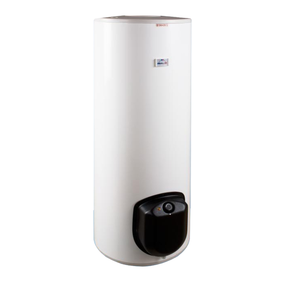
1 TECHNICAL SPECIFICATION OF PRODUCT 1.1 FUNCTION DESCRIPTION OKCE line water heaters use only electricity for heating. Their nominal performance provides sufficient amount of hot water for flat units, premises, restaurants, and similar establishments. 1.2 PRODUCT DESCRIPTION The heater tank is welded from a steel sheet; it is entirely coated with hot water resistant enamel. For additional corrosion protection a magnesium anode is mounted in the upper part of the heater to adjust the electric potential inside the tank, lowing the risk of corrosion. -
Page 5: Construction And General Heater Dimensions
1.3 CONSTRUCTION AND GENERAL HEATER DIMENSIONS OKCE 100 S/2,2 kW, OKCE 125 S/2,2 kW Figure 1 TYPE OKCE 100 S/2,2 kW OKCE 125 S/2,2 kW 3/4" vnější 1050 ① 1050 3/4" vnitřní ② 1/2" vnitřní ③ - 5 -... - Page 6 OKCE 160 S/2,2 kW, OKCE 200 S/2,2 kW, OKCE 250 S/2,2 kW 3/4" vnější ① 3/4" vnitřní ② Figure 2 TYPE OKCE 160 S/2,2 kW OKCE 200 S/2,2 kW OKCE 250 S/2,2 kW 1047 1357 1537 1279 1459 1059 OKCE 160 S/3-6 kW, OKCE 200 S/3-6 kW, OKCE 250 S/3-6 kW 3/4"...
- Page 7 OKCE 300 S/1 MPa 1578 3/4" vnější ① 3/4" vnitřní ② Figure 4 OKCE 400 S/1 MPa, OKCE 500 S/1 MPa OKCE 400 S/1MPa OKCE 500 S/1MPa 1194 1269 1289 1414 1790 1790 1920 1924 Figure 5 - 7 -...
-
Page 8: Technical Parameters
OKCE 750 S/1 MPa, OKCE 1000 S/1 MPa OKCE 750 S/1MPa OKCE 1000 S/1MPa 1998 2025 1643 1671 1010 1908 1911 1143 1154 1638 1646 1473 1511 Figure 6 1.4 TECHNICAL PARAMETERS OKCE 160 OKCE 200 OKCE 250 S/2,2 kW S/2,2 kW S/2,2 kW OKCE 100... -
Page 9: Operation And Fitting Instructions
OKCE 300 OKCE 400 OKCE 500 OKCE 750 OKCE 1000 S/1MPa S/1MPa S/1MPa S/1MPa S/1MPa CAPACITY [l] 1000 WEIGHT [kg] OPERATING PRESSURE OF ACCUMULATOR [MPa] MAX TEMPERATURE OF HSW [°C] HEATING TIME depending on the power of built-in heating unit FROM 10°C TO 60°C LOAD PROFILE DAILY ELECTRICITY... -
Page 10: Electric Installation
2.2 ELECTRIC INSTALLATION 2.2.1 GENERAL INFORMATION FOR ELECTRIC INSTALLATION Perform the connection according to the scheme. Factory connection must not be changed! (Figure 8). In the electric wiring casing remove the partition corresponding with the input wire diameter of 8 or 10 (Figure 7). -
Page 11: Mpa
Parameters of an electric heating unit for: OKCE 160 S/2,2 kW, OKCE 160 S/3-6 kW, OKCE 200 S/2,2 kW, OKCE 200 S/3-6 kW, OKCE 250 S/2,2 kW, OKCE 250 S/3-6 kW... - Page 12 (protector). The degree of protection of electric parts of the heater is IP 44. Heating unit – flanges OKCE 160 S/2,2 kW, OKCE 200 S/2,2 kW, OKCE 300 S/1 MPa OKCE 250 S/2,2 kW...
- Page 13 OKCE 160 S/3-6 kW, OKCE 200 S/3-6 kW, OKCE 250 S/3-6 kW, OKCE 300 S/1 MPa TPK 210-12/3-6 kW OKCE 300 S/1 MPa , OKCE 400 S/1 MPa, OKCE 500 S/1 MPa TPK 210-12/5-9 kW TPK 210-12/8-12 kW Mounting 12 x M12 Figure 12 Wiring scheme Notice: Factory connection must not be changed!
- Page 14 Heating unit 3-6 kW The 3-6 kW heating unit allows 4 types of connection based on either required time of heating or possibilities of electric network in the place of use. TPK 3-6 kW R ~ 1 kW To achieve chosen performance of the heating unit, connect the inlet conductor to L1,L2,L3, and N terminal board and interconnect the clips on the 1-10 terminal board in accordance with the following schemes:...
-
Page 15: Wiring For: Okce 300 S/1Mpa, Okce 400 S/1 Mpa , Okce 500 S/1Mpa, Okce 750 S/1Mpa, Okce 1000 S/1Mpa
2.2.4 WIRING FOR: OKCE 300 S/1MPA, OKCE 400 S/1 MPA , OKCE 500 S/1MPA, OKCE 750 S/1MPA, OKCE 1000 S/1MPA Heating units use Capacity Flanges size Time of heating from 10°C to 60°C (hours) flange ∅150 RDU 18-6 RDW 18-7,5 RDW 18-10 RSW 18-12 RSW-18-15... -
Page 16: Plumbing Fixture
Time of heating from 10°C to 60°C (hours) Capacity 14,1 TPK 210/3- TPK 210/3- TPK 210/5- TPK 210/3- TPK 210/5- TPK 210/8 - TPK 210/5 - TPK 210/8- TPK 210/8- 210/2,2 Wiring 2,2 kW 3 kW 4 kW 5 kW 6 kW 7 kW 8 kW... -
Page 17: Further Information
Before putting the safety valve into operation it always needs to be checked by manual removal of the membrane from the valve seat and turning the make-and-break device button always in the direction of the arrow. After being turned, the button must click back into a notch. -
Page 18: Putting The Heater Into Operation
2.5 PUTTING THE HEATER INTO OPERATION After connecting the heater to the water main, electrical power system, and after checking the safety valve (following the instructions attached to the valve), the heater can be put into operation. Procedure: Check the water main and wiring. Check proper placement of thermostat sensors. The sensors must be inserted all the way in;... -
Page 19: Heater Cleaning And Anode Rod Exchange
2.6 HEATER CLEANING AND ANODE ROD EXCHANGE Repetitive water heating causes limestone sediment on both the tank walls and chiefly the flange lid. The sedimentation depends on the hardness of water heated, its temperature, and amount of hot water consumed. We recommend checking and cleaning the tank from scale, if necessary, inspection and possible replacement of anode rod, after two years of operation. -
Page 20: Servicing Of Thermostat
3 SERVICING OF THERMOSTAT 3.1 SERVICING 3.1.1 SERVICE DEVICES OF HEATERS Service devices of heaters of 100, 125 l capacity are located under the transparent guard of the control panel (Figure 18). Thermostat knob Electric circuit power indicator lamp Tipping transparent guard Figure 18 3.1.2 TEMPERATURE SETTING Water temperature is set by turning the thermostat knob. -
Page 21: Functional Defects
3.2 FUNCTIONAL DEFECTS DEFECT CONTROL LIGHT FAILURE Water in the tank is cold is on Heating element failure Some elements are not heating Water in the tank is not is on Failure of one of the warm enough elements ... -
Page 22: Disposal Of Packaging Material And Functionless Product
It is not allowed to handle the thermostat, aside from temperature resetting with a control button. All electric installation handling, setting, and regulation feature exchange, may only be implemented by a service company. Both the electric and water installation must follow and meet the requirements and regulations relevant in the country of use! 4.2 DISPOSAL OF PACKAGING MATERIAL AND FUNCTIONLESS PRODUCT... -
Page 23: Assembly Guide For Zip-Fastener Insulation
5 ASSEMBLY GUIDE FOR ZIP-FASTENER INSULATION (Only concerns heaters with the capacity of 750 and 1000 litres) Two people are enough to implement the insulation assembly; three people are required for larger boilers; the assembly must be implemented in areas with the temperature of at least 18°C. If the insulation includes tank bottom insulation, the latter must be mounted first.
Need help?
Do you have a question about the OKCE 160 S/2,2 kW and is the answer not in the manual?
Questions and answers