Table of Contents
Advertisement
Quick Links
Advertisement
Table of Contents

Summary of Contents for Patton electronics 574
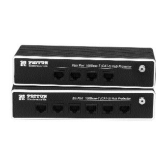
- Page 1 Part# 07M57x/58x Doc# 074100U, Rev. B Revised 1/23/08 An ISO-9001 Certified Company USER M A N UA L MODEL 5 7 4 , 5 7 6 , 5 7 8 , 5 8 4 , 5 8 6 , 5 8 8 Standalone Hub 100Base-T (CAT-5) Surge Protectors...
-
Page 2: Warranty Information
1.0 WARRANTY INFORMAT I O N Patton Electronics warrants all Model 57x/58x components to be free from defects, and will—at our option—repair or replace the prod- uct should it fail within one year from the first date of shipment. This warranty is limited to defects in workmanship or materials, and does not cover customer damage, abuse or unauthorized modification. -
Page 3: General Information
2.0 GENERAL INFORMAT I O N Thank you for your purchase of this Patton Electronics product. This product has been thoroughly inspected and tested and is warrant- ed for One Year parts and labor. If any questions or problems arise during installation or use of this product, please contact Patton Electronics Customer Service at (301) 975-1007. -
Page 4: Product Applications
Model’s 57x and 58x surge protectors are easy to install and are designed to operate transparently to your network. This section describes cohnnection procedures for both models. 3.1 PRODUCT APPLICATIONS Both Models 57x and 58x protect all eight pins on the modular RJ-45 Cat-5 interface, and work in environments with data rates up to 100 Mbps. - Page 5 Also, the flat braided grounding wire(s) on the Model 57x should be attached to the grounded metal frame of the device being protect- ed. If it is not possible to attach it to the equipment being protected, contact Patton Technical Support (See Section 1.1). 3.1.2 BARRIER APPLICATION (MODEL 58x) The Model 58x is a more robust protector than the Model 57x, and is designed for use as a barrier protector on LAN equipment in...
-
Page 6: Installation Procedures
1. Turn off equipment power and disconnect the existing connection between the UTP cable and the equipment’s I/O port. 2. Install the surge protector between the incoming UTP line and the protected equipment, as in Figure 3, below. This installation requires a straight through Cat-5 patch cable with modular RJ-45 male connectors . - Page 7 3.2.2 Connecting the Model 58x at a Barrier (Wall, Building, Entrance, etc.) 1. Disconnect the UTP cable from the wall jack or patch panel jack. 2. Install the Model 58x between the UTP line and the jack. This installation requires a straight through Cat-5 patch cable with modular RJ-45 male connectors.
-
Page 8: Specifications
Environment: Category-5 Interfaces that utilize the RJ-45 connector, including RS-422, 423, 10Base- T, Token Ring, Fast Ethernet, 100Base-T, 100Base-T4 and ATM Connectors: RJ-45 Female Response Time: Clamped to 13V after 0.1μS Characteristic Impedance: 100 Ohms NEXT Loss (worst pair): Better than -40 dB at 100 MHz Surge Clamping Voltages: Model 57x: 13 V max with 1 KV Input;... - Page 9 INTERNATIONAL ELECTROTECHNICAL COMMISSION (IEC) COM- Meets IEC standards 801.2, 801.4 and 801.5 (CE Mark) Effective January 1996 the European Economic Community will require that all electronic devices be tested and comply with all appli- cable International standards relating to the product type and category of use.
- Page 10 EIA/TIA TSB-40A COMPLIANCE The Model 57x/58x series surge protectors have been designed to conform to stringent EIA/TIA TSB-40 standards as required for all Category-5 connecting hardware. These standards specify the capaci- tance and near end cross-talk (N.E.X.T) to insure proper operation of ALL connected equipment.
- Page 11 APPENDIX C (continu e d ) TSB-40A COMPLIANCE TESTING RESULTS TYPICAL ATTENUATION MEASUREMENT Freq Pins: 1-2 Pins: 3-6 35.25 62.5 Figure C-3. Attenuation Measurements for Patton Model 57x Freq Pins: 1-2 Pins: 3-6 35.25 62.5 Figure C-4. Attenuation measurements for Patton Model 58x Pins: 4-5 Pins:7-8 Pins: 4-5...
- Page 12 APPENDIX C (continu e d ) TSB-40A COMPLIANCE TESTING RESULTS TYPICAL RETURN LOSS MEASUREMENT Freq Pins: 1-2 Pins: 3-6 34.0 28.0 38.0 38.0 39.0 41.0 38.0 41.0 34.0 35.0 33.7 33.0 31.0 30.0 31.25 28.1 27.0 62.5 21.0 22.0 17.0 21.0 Figure C-5.
- Page 13 Appendix C (continued) TSB-40A Compliance Testing Results TYPICAL INSERTION LOSS MEASUREMENT Pin Number: Figure C-7. Patton Model 57x Series Insertion Loss Measurement Pin Number: Figure C-8.Patton Model 58x Series Insertion Loss Measurement DC Resistance Milliohms DC Resistance Milliohms...
- Page 14 Dear Valued Customer, Thank you for purchasing Patton Electronics products! We do appreciate your business. I trust that you find this user manual helpful. We manufacture one of the widest selections of data communica- tions products in the world including CSU/DSU's, network termination units, powered and self-powered short range modems, fiber optic modems, interface converters, baluns, electronic data switches, data-line surge protectors, multi- plexers, transceivers, hubs, print servers and much more.


Need help?
Do you have a question about the 574 and is the answer not in the manual?
Questions and answers