Table of Contents
Advertisement
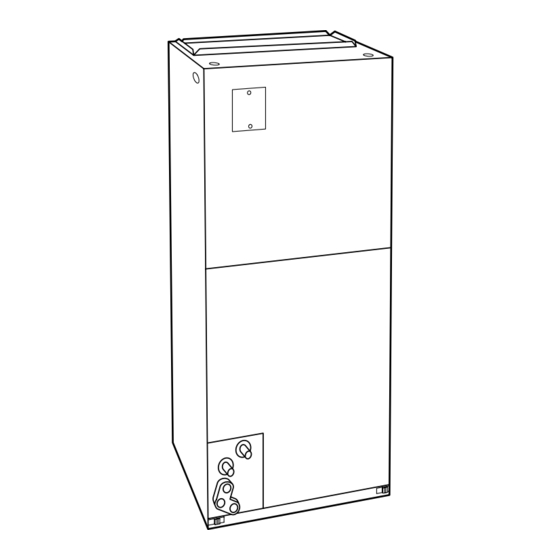
Fan Coil for Puron® Refrigerant
002, 003, 005, 006
NOTE: Read the entire instruction manual before starting the installation.
This symbol → indicates a change since the last issue.
Improper installation, adjustment, alteration, service, maintenance, or use can cause explosion, fire, electrical shock, or other conditions which may
cause personal injury or property damage. Consult a qualified installer, service agency, or your distributor or branch for information or assistance.
The qualified installer or agency must use factory-authorized kits or accessories when modifying this product. Refer to the individual instructions
packaged with kits or accessories when installing.
Follow all safety codes. Wear safety glasses and work gloves. Use quenching cloth for brazing operations. Have fire extinguisher available. Read
these instructions thoroughly and follow all warnings or cautions attached to the unit. Consult local building codes and National Electrical Code
(NEC) for special requirements.
Recognize safety information. This is the safety-alert symbol
the potential for personal injury.
Understand the signal words DANGER, WARNING, CAUTION, and NOTE. These words are used with the safety-alert symbol. DANGER
identifies the most serious hazards which will result in severe personal injury or death. WARNING signifies hazards which could result in personal
Form: IM-FV4B-02
Installation Instructions
Fig. 1—Model FV4B
SAFETY CONSIDERATIONS
. When you see this symbol on the unit and in instructions manuals, be alert to
Cancels: IM-FV4B-01
Printed in U.S.A.
6-03
FV4B
A98023
Catalog No. 63FV-4B1
Advertisement
Table of Contents

Subscribe to Our Youtube Channel
Related Manuals for Carrier FV4B


Summary of Contents for Carrier FV4B
-
Page 1: Installation Instructions
Fan Coil for Puron® Refrigerant FV4B 002, 003, 005, 006 A98023 Fig. 1—Model FV4B NOTE: Read the entire instruction manual before starting the installation. This symbol → indicates a change since the last issue. SAFETY CONSIDERATIONS Improper installation, adjustment, alteration, service, maintenance, or use can cause explosion, fire, electrical shock, or other conditions which may cause personal injury or property damage. - Page 2 FV4B Fan Coils can be installed for upflow and horizontal-left applications as factory shipped. (See Fig. 2, 4 and 8.) Units can be installed for horizontal-right applications with field modifications. Units may be converted for downflow applications using factory-authorized accessory kits.
- Page 3 POWER ENTRY FIELD SUPPLIED OPTIONS SUPPLY DUCT LOW VOLT ENTRY OPTIONS 002-005 21-IN. 24-IN. FRONT SERVICE CLEARANCE UNIT 19 In. A COIL UNITS UPFLOW/DOWNFLOW SECONDARY DRAIN ⁄ ″ UPFLOW/DOWNFLOW 19 ″ PRIMARY DRAIN FIELD MODIFIED SIDE RETURN LOCATION FOR ⁄ ″...
- Page 4 A-COIL HORIZONTAL LEFT PRIMARY SECONDARY DRAIN FIELD DRAIN SUPPLIED HANGING STRAPS 002-005 21-IN. 006 24-IN. FRONT SERVICE CLEARANCE (FULL FACE UNIT OF UNIT) LOW VOLT ENTRY OPTIONS 1 3 /4 IN. FILTER ACCESS CLEARANCE PRIMARY DRAIN SECONDARY DRAIN POWER ENTRY OPTIONS A00096 Fig.
- Page 5 REFRIGERANT AIR SEAL CONNECTIONS ASSEMBLY HORIZONTAL RIGHT APPLICATION COIL SUPPORT RAIL COIL BRACKET DRAIN PAN SUPPORT BRACKET COIL SUPPORT RAIL COIL BRACKET HORIZONTAL DRAIN PAN PRIMARY DRAIN HORIZONTAL RIGHT SECONDARY DRAIN HORIZONTAL RIGHT A00071 Fig. 6—A-Coil in Horizontal-Right Application 8. Slide coil assembly into casing. Be sure coil bracket on each corner of vertical pan engages coil support rails. 9.
- Page 6 Duct connection flanges are provided on unit air discharge connection. When using FV4B units with 20-, 24-, and 30-kw electric heaters, maintain a 1-in. clearance from combustible materials to discharge plenum and ductwork for a distance of 36 in. from unit. Use accessory downflow base to maintain proper clearance on downflow installations.
- Page 7 C. Intelligent Heat Staging Option Intelligent Heat staging of the electric heat package is possible when the FV4B is installed as a part of a single-speed heat pump system using a corporate 2-speed programmable thermostat (model TSTATXXP2S01-B), Thermidistat™ Control, or capable zoning control and any 1 of the following electric heat packages: Relay heaters KFCEH1401N09, KFCEH1501F15, KFCEH1701C15, KFCEH1801F20, KFCEH1901C20, KFCEH2101F24, OR KFCEH2201F30.
- Page 8 24 VAC COMM HUMIDIFY HUMIDIFIER (24 VAC) OUTDOOR SENSOR OUTDOOR SENSOR CONNECTION A98477 Fig. 9—FV4B Fan Coil Wiring with 1-Speed Air Conditioner INDOOR CONTROL FAN COIL 2-SPEED AIR CONDITIONER HEAT STAGE 2 O/W2 REMOVE J2 JUMPER FOR HEAT STAGING HEAT STAGE 1...
- Page 9 CONNECTION A02005 Fig. 12—FV4B Fan Coil Wiring with 2-Speed Puron Heat Pump CAUTION: Wrap a wet cloth around rear of fitting to prevent damage to TXV and factory-made joints. Failure to follow this CAUTION could result in minor personal injury or product and property damage.
- Page 10 (See Fig. 17 and 18.) The FV4B Fan Coil must be configured to operate properly with system components with which it is installed. To successfully configure a basic system (see information printed on circuit board label located next to select pins), move the 6 select wires to the pins which match the components used.
- Page 11 UNIT 2” MIN 2” MIN A03002 Fig. 14—Recommended Condensate Trap DO NOT USE SHALLOW RUNNING TRAPS! A03013 Fig. 15—Insufficient Condensate Trap FILTER ACCESS PANEL SECONDARY DRAIN WITH APPROPRIATE TRAP REQUIRED (USE FACTORY KIT OR FIELD-SUPPLIED TRAP) PRIMARY TRAP REQUIRED (USE FACTORY KIT OR FIELD-SUPPLIED TRAP OF SUFFICIENT DEPTH.
- Page 12 24VAC HEATER/MOTOR MOLEX 12-PIN CONNECTOR A95275 Fig. 17—Detail of FV4B Printed-Circuit Board C. SYSTEM TYPE - Select system type installed AC or HP The type of system must be selected: 1. AC - Air conditioner 2. HP-COMFORT - Heat Pump Comfort provides approximately 315 CFM per ton for higher normal heating air delivery temperature.
- Page 13 I. COMFORT OPTIONS - WARMER HEATING AND SUPER DEHUMIDIFY (See Fig. 21 for Quick Reference Guide) The FV4B Fan Coil provides better than average humidity control and heated air temperature. This configuration will improve the comfort provided by the heat pump system if more humidity removal or if warmer heating air is desired. While providing this improved comfort, the heat pump system will operate efficiently, but not at the published HSPF or ARI SEER efficiency.
- Page 14 The AUX1 and AUX2 terminals are not always energized during blower operation, as described above. When using an electronic air cleaner with the FV4B Fan Coil, use Airflow Sensor Part No. KEAAC0101AAA. The airflow sensor turns on electronic air cleaner when the fan coil blower is operating.
- Page 15 PROCEDURE 10—FV4B FAN COIL SEQUENCE OF OPERATION The FV4B will supply airflow in a range which is more than twice the range of a standard fan coil. It is designed to provide nominal cooling capacities at a 50°F evaporator temperature and the required airflow which enables it to match with 4 air conditioner or heat pump system sizes.
- Page 16 2. Airflow can be adjusted +15 percent or -10 percent by selecting HI or LO respectively for all modes except fan only. 3. Dry coil at 230 volts and with 10kw heater and filter installed. 4. Airflows shown are at standard air conditions. Table 4—FV4B Fan Coil Airflow Delivery (CFM) in Heat Pump Only Heating Mode OPERATING MODE Two-Speed...
- Page 17 1810 2085 1750 1810 2085 * Airflow not recommended for heater/system size. NOTE: LO, NOM, and HI refer to AC/HP CFM ADJUST selection. Table 6—FV4B Minimum CFM for Electric Heater Application HEAT PUMP COIL UNIT HEATER SIZE KW UNIT SIZE...
- Page 18 J1 JUMPER – PULL FOR DEHUMIDIFICATION CONTROL LOW VOLTAGE SCREW TERMINALS J2 JUMPER – PULL FOR HEAT STAGING SEC1 SEC2 DEHUMIDIFICATION INPUT EASY SELECT 24 VAC HOT AUX HEAT KW/CFM 0-30 0-20 0-10 1075 AUXILARY HEAT STAGE 1 AUXILIARY HEAT STAGE 2 AC/HP SIZE LOW SPEED COMPRESSOR SYSTEM TYPE...
- Page 19 Table 7—Wiring Connections of FV Fan Coil Wiring Harness 16-IN PLUG ON WIRING HARNESS TO MOTOR WIRING HARNESS CONNECTION TO EASY SELECT BOARD Signal on Pin with Pin on 12-Pin Plug Pin on 16-Pin Plug Description Wire Color Screw Terminal or Set-up Selection Jumpered to R* Common...
- Page 20 A03100 → Fig. 22—Set-Up Instructions for Warmer Heating Temperatures and Super Humidity Control in Cooling 3. Inspect blower motor and wheel for cleanliness each heating and cooling season. Clean as necessary. 4. Inspect electrical connections for tightness and controls for proper operation each heating and cooling season. Service as necessary. Consult Fan Coil Service Manual available from equipment distributor for maintenance procedures.
- Page 21 PURON® QUICK REFERENCE GUIDE FOR INSTALLERS AND TECHNICIANS • Puron refrigerant operates at 50-70 percent higher pressures than R-22. Be sure that servicing equipment and replacement components are designed to operate with Puron. • Puron refrigerant cylinders are rose colored. •...
- Page 22 —22—...
- Page 23 —23—...
- Page 24 imfv4B02 —24— © 2003 CAC/BDP 7310 W. Morris St., Indianapolis, IN 46231 Book/Tab: 1/4,3d/2e Catalog No. 63FV-4B1...
Need help?
Do you have a question about the FV4B and is the answer not in the manual?
Questions and answers