
Related Manuals for ATC Sun Ray Neptune


Summary of Contents for ATC Sun Ray Neptune
- Page 1 Sun Ray Neptune Low Level Thermal Electric Radiator Installation and Operation Guide Models Type Wattage No. of Fins Size (HxWxD) (mm) Net Weight (kg) LR950 950w 340x865x96 12.8 LR1425 1425w 340x1265x96 19.2...
-
Page 2: Installation
Installation General Information This appliance must be connected to a 230V 50Hz power supply. This appliance must be connected to a switched fused spur. The main installation must be protected by a 2 pole switch where the distance between contacts must be a minimum of 3mm. Power Cord Wires = Neutral (Grey or Blue) Live (Brown) - Page 3 provided that it has been placed or installed in its intended normal operating position and they have been given supervision or instruction concerning use of the appliance in a safe way and understand the hazards involved. Children aged from 3 years and less than 8 years shall not plug in, regulate and clean the appliance or perform user maintenance.
-
Page 4: Electric Power
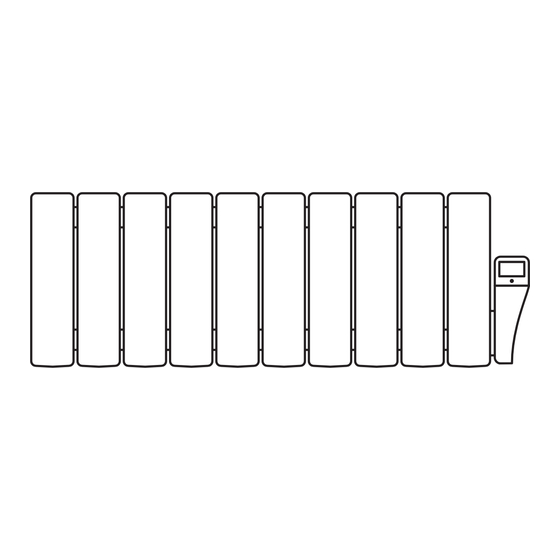
Main Components The body of the Sun Ray Neptune consists of special cast aluminium fins, specifically designed to ensure a maximum rate of heat diffusion, the air circulation channels providing a very effective convection effect. - Page 5 Mark the appropriate location and fix the brackets in place with the supplied plugs and screws, ensuring the brackets are installed in the correct position (figure 2). Figure 2 Once the brackets have been installed the radiator can be hung from the supports (figure 3). To lock the radiators in place press on the ratchet and turn until a click is heard (figure 4).
-
Page 6: Operation
Operation The room temperature is controlled by the electronic thermostat in the control end placed at the side of the appliance. The thermostat has a precision of ±0.3ºC. Controller: Buttons and Symbols Switching On Once power has been supplied to the radiator it will initially be in the standby mode. Setting the Clock 1. -
Page 7: Mode Change
Mode Change Press the Mode button to change between the mode screens shown below: Pilot Wire (Please note the pilot wire system controller is not available) Comfort Temperature Setting Press the Mode button until comfort is selected, then press the + or - to adjust the temperature. Pressing either button continuously for more than 5 seconds will change the temperature rapidly. -
Page 8: Programme Mode
Programme Mode The programme mode has three options; programme 1 and programme 2 are pre-set as shown below and programme 3 can be set to the users requirements. E= Economy Mode, C=Comfort Mode To select a programme, press the mode button until the programme mode is selected and use the time button to select P1, P2 or P3. - Page 9 Programming – Quick Guide Tip: Write down required times and modes before starting. Before we set the programme we must set the clock. When we programme we set the times for the comfort and economy modes to be in operation. Setting the mode's temperature is done seperately.
-
Page 10: General Description
The Remote Control (Optional) General Description The remote control communicates with the radiator using infra-red signal from a maximum distance of 10m from the appliance and requires 2x AAA batteries. ECO Button Temperature IR transmision ‘+’ Button Operating Mode Time Button Mode Button Time Day of the week... -
Page 11: Low Battery Warning
IR Transmission Any alterations made using the remote control will be sent to the radiator via an IR signal after 1 second of inactivity. This can be seen by the IR transmission symbol flashing in the top right hand corner. Low Battery Warning When the battery is running low the display will periodically display ‘bAtt’... -
Page 12: Maintenance And Care
SunRay Radiators clean may result in dust becoming burnt and depositing on the wall above the heater in the form of dark streaks or patches. This type of marking is expressly due to failure to keep the heater and surrounding area clean. ATC take no responsibility for any such damage caused...
Need help?
Do you have a question about the Sun Ray Neptune and is the answer not in the manual?
Questions and answers