Table of Contents
Advertisement
Quick Links
Advertisement
Table of Contents

Related Manuals for BECKWITH ELECTRIC M-0329B


Summary of Contents for BECKWITH ELECTRIC M-0329B
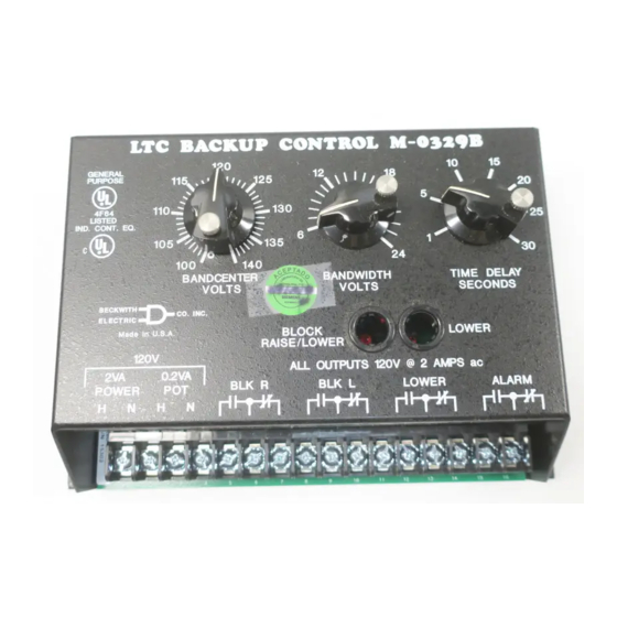
- Page 1 Instruction Book M-0329B LTC Backup Control...
- Page 2 CONTROLS LTC Backup Control M-0329B • Prevents a defective LTC tapchanger control from running the voltage outside the upper or lower limits • Prevents the line drop compensator from raising the voltage too high under full or overload conditions •...
- Page 3 Selectable Deadband: The deadband is the voltage range above the Block Raise Level where no tap changer operation takes place. In the M-0329B, it is selectable as 1, 2, 3, or 4 V rms. Measured voltages above the Block Raise Level plus the deadband will cause the control to immediately issue a Lower command.
- Page 4 Fungus Resistance: A conformal printed circuit board coating inhibits fungus growth. Transient Protection Input and output circuits are protected against system transients. The M-0329B will pass all the requirements of ANSI/IEEE C37.90.1-1989, which defines oscillatory and fast transient surge withstand capability. All inputs and outputs will withstand 1500 V ac to chassis or instrument ground for one minute.
- Page 5 BECKWITH ELECTRIC CO., INC. 6190 - 118th Avenue North • Largo, Florida 33773-3724 U.S.A. PHONE (727) 544-2326 • FAX (727) 546-0121 E-MAIL marketing@beckwithelectric.com WEB PAGE www.beckwithelectric.com ©1998 Beckwith Electric Co. Printed in U.S.A. (06.19.02) 800-0329B-SP-02MC2 09/03...
- Page 6 WARNING DANGEROUS VOLTAGES, capable of causing death or serious injury, are present on the external terminals and inside the equip- ment. Use extreme caution and follow all safety rules when han- dling, testing or adjusting the equipment. However, these internal voltage levels are no greater than the voltages applied to the exter- nal terminals.
- Page 7 PRODUCT CAUTIONS Before attempting any test, calibration, or maintenance procedure, personnel must be completely familiar with the particular circuitry of this unit, and have an adequate understanding of field effect devices. If a component is found to be defective, always follow replacement procedures carefully to that assure safety features are maintained.
-
Page 8: Table Of Contents
Figure 4 External Connections ..................4 Application ........................5 Figure 5 Power and Voltage Input Connections ............5 Figure 6 M-0329B Interconnections with Beckwith Tapchanger Controls and Regulator ................5 Table 1 TCC Connections ................... 6 Figure 7 Interconnections for use with Centrifugal-type Capacitor Drive Motors ..7 Adjustment ........................ - Page 9 Table 3 Typical Voltages ..................16 10.1 Typical Resistances ....................17 Table 4 Typical Resistances ..................17 Figure 11 Component Location ................. 18 11.1 Calibration ........................19 Parts List ........................20 © Beckwith Electric Co., Inc. Printed in U.S.A. (06.25.02) 800-M0329B-IB-01MC2 09/03...
-
Page 10: Introduction
Designed to replace the Beckwith M-0029 LTC the TIME DELAY control. Control Backup Relay as well as the M-0145 First Blocking contacts on the M-0329B will operate Customer Protector, the single-phase, solid-state within 0.2 seconds after a voltage excursion to... -
Page 11: Installation
Since sudden changes in the transformer primary voltage may move the secondary voltage outside the range of the LTC control and the M-0329B, a 3 minute timer is provided to allow a normal control to correct the voltage. After 3 minutes of abnormal voltage, the M-0329B ALARM contact will indicate an abnormal condition. - Page 12 M-0329B Instruction Book 1-1/8" Max (2.86 cm) 2-3/8" (6.03 cm) 8-1/4" (20.96 cm) 1/2" (1.27 cm) 4-3/4" 4-3/4" (12.07 cm) (12.07 cm) 5-3/4" (14.61 cm) 1/4" (.64 cm) 7-3/4" (19.69 cm) 8-3/4" (22.23 cm) ■ ■ ■ ■ ■ NOTE: Panel mount using four #10 bolts Figure 2 Mounting and Outline Dimensions –3–...
-
Page 13: Terminal Block Connections
M-0329B Instruction Book Terminal Block Connections the figure below. The wire should be No. 16 AWG The M-0329B LTC Backup Control is listed to UL inserted in an AMP #51864-1 (or equivalent) Standards for Safety by Underwriters Laboratories connector, and both screws tightened to 16 inch- Inc. -
Page 14: Application
84R - Raise Motor Auxiliary Relay 84L - Lower Motor Auxiliary Relay ■ ■ ■ ■ ■ NOTE: *If first customer protection is not required, delete these connections. Figure 6 M-0329B Interconnections with Beckwith Tapchanger Controls and Regulator –5–... - Page 15 M-0329B Instruction Book Table 1 TCC Connections –6–...
- Page 16 M-0329B Instruction Book Figure 7 Interconnections for use with Centrifugal-Type Capacitor Drive Motors –7–...
-
Page 17: Adjustment
AC/DC Converter Adjustment The Voltage Input, TB1-3 to TB1-4, is the voltage that the M-0329B will monitor to provide the voltage Accurately calibrated dials, labeled BANDCENTER protection functions described previously. The input and BANDWIDTH, set the Block Raise and Block protection circuitry for the Sensing Input is the Lower voltage levels. -
Page 18: Lower Time Delay
The ALARM relay provides an indication that the dc level. If the level is below 13.7 V dc, the output at M-0329B is in a blocking condition or that the power U3-1 will be low, forcing the output at U4-10 low. - Page 19 M-0329B Instruction Book TP21 -24V +24V 120VAC LM317 TB1-1 U-0256 VOUT +15V 2W,5 1N4004 1N4004 R102 .05uf .01uf .01uf 470uf 1N5365B 600V 250V .01uf 1/4W,1 R103 TB1-2 125V 1.37K NEUTRAL 1N4004 1N4004 1/4W,1 LH0070 1.5K -15V +10V 2W,10 .01uf .01uf...
- Page 20 M-0329B Instruction Book BANDWITH BANDCENTER TIME DELAY VOLTS VOLTS SECONDS LTC BACKUP CONTROL X-0329B 500K FRONT PANEL CONNECTIONS +10V 53.6K 56.2K 2.37 1/8W,1 1/8W,1 1/8W,1 T P 1 0 1.87K 1 / 8 W, 1 R 1 6 1/8W,1 1 / 2 W , 2 0...
-
Page 22: Maintenance
■ ■ ■ ■ ■ NOTE: Units returned with only a blown fuse Due to the extremely sophisticated nature of the circuitry in the M-0329B, field repair is not are not covered by warranty and a nominal repair charge will be made for recommended. -
Page 23: Test Procedure
M-0329B Instruction Book Test Procedure Please refer to the WARNING page at the beginning A high impedance true rms digital of this manual before proceeding. multimeter with an ac accuracy of at least ±0.02% of reading, Fluke 45 or Refer to Figure 10 for the test setup. -
Page 24: Test Setup
Block Raise Remove the 120 V ac power source Repeat Step 1 at 12 V Bandwidth, 18 V from the M-0329B. The ALARM relay Bandwidth, and 24 V Bandwidth. should de-energize without a time delay. The Bandwidth should be within ±10% of setting. -
Page 25: Removing The Printed Circuit Board
▲ ▲ ▲ ▲ ▲ CAUTION: If the M-0329B fails to operate Visually inspect the board for any properly and you choose to repair the unit, it is... -
Page 26: 10.1 Typical Resistances
M-0329B Instruction Book 10.1 Typical Resistances Conditions All terminals are open circuited. Measurements are made with a Fluke 45 digital multimeter. Ω Ω 0 2 Ω Ω 0 2 Ω Ω 0 2 Ω Ω 0 2 Ω Ω Table 4 Typical Resistances... -
Page 28: 11.1 Calibration
M-0329B Instruction Book 11.1 Calibration ■ ■ ■ ■ ■ NOTE: The M-0329B has been fully calibrated Bandwidth at the factory prior to shipment. There is Set the BANDWIDTH dial to 12 V. no need to recalibrate the unit before Slowly raise the voltage input until the initial installation. -
Page 29: Parts List
Parts not marked with an asterisk are normally available from an electronics components house. Those parts or a current substitute will normally be available from Beckwith Electric stock. In either case, when parts are ordered from Beckwith Electric, we will be responsible for supplying the current replacement in the shortest possible time. - Page 30 M-0329B Instruction Book COMPONENT BECO DESCRIPTION DESIGNATION NUMBER CR1-CR6,CR15,CR22 400-00271 Diode, IN4004, SMT CR7-CR13,CR16-CR20, 400-00264 Diode, MMBD4148, SMT CR23 CR14,CR21 400-00279 Diode, MMBD 1501/A, SMT CR24,CR25 400-00722 Diode, Light Emitting 420-00719 Fuse, 1 A 420-00725 Fuse, 1/2 A 030-00015 Contact Housing, 6-position...
- Page 31 M-0329B Instruction Book COMPONENT BECO DESCRIPTION DESIGNATION NUMBER 360-00038 Potentiometer, 50 K 188-07500 Resistor, 750 ±1%, 1/8 W, SMT Potentiometer, 200 Ω 360-00034 188-01781 Resistor, 1.78 K ±1%, 1/8 W, SMT 188-064R9 Resistor, 64,9 ±1%, 1/8 W, SMT 188-024R3 Resistor, 24.3 ±1%, 1/8 W, SMT Resistor, 102 Ω...
- Page 32 M-0329B Instruction Book COMPONENT BECO DESCRIPTION DESIGNATION NUMBER R49,R54 185-00203 Resistor, 20 K ± 5%, 1/4 W, SMT 180-00206 Resistor, 20 M ±5%,1/4 W, SMT 188-03922 Resistor, 33.2 K ±1%, 1/8 W, SMT 185-00395 Resistor, 3.9 M, ±5%, 1/4 W, SMT 188-042R2 Resistor, 41.2 ±1%, 1/8 W, SMT...
- Page 33 M-0329B Instruction Book COMPONENT BECO DESCRIPTION DESIGNATION NUMBER 400-00667 Voltage Regulator, Integrated Circuit, LH0070-OH 560-00043 Quad Op Amp, Integrated Circuit, CA224, SMT 560-00042 Quad Op Amp, Integrated Circuit, TLC274, SMT 540-00097 Quad 2 AND Gate, CD4081B D/M, SMT 560-00008 Voltage Regulator, LM317, 40V...
- Page 34 There shall be no warranties which extend beyond those contained in the Beckwith Electric Co., Inc. terms of sale. All rights reserved by Beckwith Electric Co., Inc. No reproduction may be made without prior written approval of the Company.
- Page 35 BECKWITH ELECTRIC CO., INC. 6190 - 118th Avenue North • Largo, Florida 33773-3724 U.S.A. PHONE (727) 544-2326 • FAX (727) 546-0121 E-MAIL marketing@beckwithelectric.com WEB PAGE www.beckwithelectric.com © Beckwith Electric Co. Printed in USA 800-0329B-IB-01MC2 09/...
Need help?
Do you have a question about the M-0329B and is the answer not in the manual?
Questions and answers