Table of Contents
Advertisement
Advertisement
Table of Contents

Related Manuals for BECKWITH ELECTRIC M-3425


Summary of Contents for BECKWITH ELECTRIC M-3425
- Page 1 Instruction Book M-3425 Generator Protection...
- Page 2 PROTECTION Generator Protection M-3425 ® Integrated Protection System for Generators of All Sizes Unit shown with optional M-3925 Target Module and M-3931 HMI (Human-Machine Interface) Module. • Provides all major protective functions for generator protection, including Field Ground (64F), Out-of-Step (78), and Split-Phase Differential (50DT) ®...
- Page 3 • Two-step Rate of Change of Frequency (81R) • Generator Phase Differential protection (87) • Ground Differential (87GD) protection • External Function allows external devices to trip through M-3425 Generator Protection Relay Optional Protective Functions • Stator Thermal protection using positive se- quence inverse time overcurrent (51T) •...
- Page 4 M-3425 Generator Protection Relay STANDARD PROTECTIVE FUNCTIONS Device Setpoint Number Function Ranges Increment Accuracy † Phase Distance (dual-zone mho characteristic) 0.1 to 100.0 Ω 0.1 Ω !0.1 Ω or 5% Circle Diameter #1, #2 (0.5 to 500.0 Ω) (!0.5 Ω or 5%) –100.0 to 100.0 Ω...
- Page 5 (0.02 to 2.00 A) !1 Cycle or !1% Time Delay 1 to 8160 Cycles 1 Cycle 50BF can be initiated from designated M-3425 output contacts or progammable inputs. Instantaneous Overcurrent Pickup 0.1 to 240.0 A 0.1 A !0.1 A or !3% (0.1 to 48.0 A)
- Page 6 M-3425 Generator Protection Relay STANDARD PROTECTIVE FUNCTIONS ( cont .) Device Setpoint Number Function Ranges Increment Accuracy † Instantaneous Overcurrent, Neutral !0.1 A or !3% Pickup 0.1 to 240.0 A 0.1 A (0.1 to 48.0 A) (!0.02 A or !3%) Trip Time Response <...
- Page 7 M-3425 Generator Protection Relay STANDARD PROTECTIVE FUNCTIONS ( cont .) Device Setpoint Number Function Ranges Increment Accuracy † RMS Overvoltage !0.5 V or !0.5% Pickup #1, #2 5 to 180 V !0.8 V to !0.75%* !1 Cycle or !1%** Time Delay #1, #2...
- Page 8 M-3425 Generator Protection Relay STANDARD PROTECTIVE FUNCTIONS ( cont .) Device Setpoint † Number Function Ranges Increment Accuracy Rate of Change of Frequency !0.05 Hz/Sec. or !5% Pickup #1, #2 0.10 to 20.00 Hz/Sec. 0.01 Hz/Sec. !20 Cycles Time Delay #1, #2...
- Page 9 M-3425 Generator Protection Relay OPTIONAL PROTECTIVE FUNCTIONS Device Setpoint Number Function Ranges Increment Accuracy † Inverse Time Positive Sequence Overcurrent (I t=K), for Stator Thermal Protection !0.1 A Pickup 0.50 to 15.00 A 0.01 A (0.10 to 3.00 A) (!0.02 A)
- Page 10 M-3425 Generator Protection Relay Description The M-3425 Generator Protection Relay is suitable for all generator ratings and prime movers. Typical connection diagrams are illustrated in Figure 2, M-3425 Typical One-Line Connection Diagram, Figure 3, M-3425 Typical One-Line Connection Diagram (Configured for Split-Phase Differential), and Figure 4, M-3425 Typical Three-Line Connection Diagram.
- Page 11 • Real-time metering of all quantities measured • Downloading of recorded oscillographic data IRIG-B The M-3425 Generator Protection Relay can accept either modulated or demodulated IRIG-B time clock synchronization signal. The IRIG-B time synchronization information is used to correct the hour, minutes, seconds, and milliseconds information.
- Page 12 M-3425 Generator Protection Relay HMI Module (optional) Local access to the relay is provided through an optional M-3931 HMI (Human-Machine Interface) Module, allowing for easy-to-use, menu-driven access to all functions via six buttons and a 2-line by 24 character alphanumeric LED. Features of the HMI Module include : •...
- Page 13 Patent & Warranty The M-3425 Generator Protection Relay is covered by U.S. Patents 5,592,393 and 5,224,011. The M-3425 Generator Protection Relay is covered by a five year warranty from date of shipment. External Connections M-3425 external connection points are illustrated in Figure 1, External Connections, on the facing page.
- Page 14 M-3425 Generator Protection Relay –13–...
- Page 15 M-3425 Generator Protection Relay Utility System M-3425 Typical This function is available as a standard protective function. Connection Diagram This function is available as a Unit optional protective function. This function provides control for the function to which it points.
- Page 16 M-3425 Generator Protection Relay Utility System M-3425 Typical This function is available as a standard protective function. Connection Diagram (Configured for Split-Phase Differential) This function is available as a Unit optional protective function. This function provides control for the function to which it points.
- Page 17 OUTPUTS Figure 4 M-3425 Typical Three-Line Connection Diagram NOTE: M-3425 current terminal polarity marks (•) indicate "entering" current direction when primary current is "from" the generator. If CT connections differ from those shown, adjust input terminals. NOTE: Wire to split phase differential CTs for use with 50DT split phase function.
- Page 18 NOTE: Dimensions in brackets are in centimeters. Figure 5 Horizontal Mounting Dimensions NOTE: Panels for vertical mounting are available. When mounted vertically, the target module will be located at the top and all front-panel text will be horizontally aligned. Consult Beckwith Electric Co. for details. –17–...
- Page 19 M-3425 Generator Protection Relay 5.65 [13.41] 0.40 [1.02] x 5.59 0.27 [0.68] [14.20] SLOT (4x) ACTUAL 2.25 [5.72] 1.71 [4.34] 17.45 [44.32] 19.00 [48.26] 17.31 18.58 [43.97] [47.19] Actual 17.78 [44.65] Rear View n NOTE: Dimensions in brackets are in centimeters.
- Page 20 M-3425 Generator Protection Relay M-3921 Field Ground Coupler NOTES: The above circuit measures insulation resistance (R ) between rotor field winding and ground (64F). Relay injects !15 V squarewave (V ) and measures return signal (V ) to calculate R The injection frequency can be set (0.1 to 1.0 Hz) based on the rotor capacitance, in order to improve...
- Page 21 Figure 8 M-3921 Field Ground Coupler Mounting Dimensions BECKWITH ELECTRIC CO., INC. 6190 - 118th Avenue North • Largo, Florida 33773-3724 U.S.A. PHONE (727) 544-2326 • FAX (727) 546-0121 E-MAIL marketing@beckwithelectric.com WEB PAGE www.beckwithelectric.com © 1998 Beckwith Electric Co. 800-3425-SP-11MC5 07/03 Printed in U.S.A. (10.16.02)
- Page 22 Failure to do so will violate standards for safety in the design, manufacture, and intended use of the product. Qualified personnel should be the only ones who operate and maintain this equipment. Beckwith Electric Co., Inc. assumes no liability for the customer’s failure to comply with these requirements.
- Page 23 PRODUCT CAUTIONS Before attempting any test, calibration, or maintenance procedure, personnel must be completely familiar with the particular circuitry of this unit, and have an adequate understanding of field effect devices. If a component is found to be defective, always follow replacement procedures carefully to that assure safety features are maintained.
-
Page 24: Table Of Contents
Table of Contents Table of Contents M-3425 Generator Protection Instruction Book Chapter 1 Introduction Instruction Book Contents ..............1–1 M-3425 Generator Protection Relay ..........1–2 Accessories ..................1–4 Chapter 2 Application Configuration ..................2–1 Functions .................... 2–1 Relay System Setup ................2–3 System Diagrams ................ - Page 25 Chapter 4 Remote Operation Remote Operation................4–1 Direct Connection ................4–1 Multiple Systems Setup ..............4–2 Serial Multidrop Network Setup ............4–2 Setting up the M-3425 Generator Protection Relay for Communications ................. 4–3 Installing the Modems................ 4–3 ® Installation and Setup (IPScom ) .............
- Page 26 Table of Contents Chapter 6 Testing Equipment/Test Setup ............... 6–2 Diagnostic Test Procedures .............. 6–6 Output Test ..................6–6 Input Test ................... 6–7 Status LED Test ................6–7 Target LED Test ................6–8 Expanded I/O Test ................6–8 Button Test ..................6–8 Display Test ..................
- Page 27 M-3425 Instruction Book Appendices Appendix A: Configuration Record Forms ........A–1 Appendix B: Communications ............B–1 Appendix C: Self-Test Error Codes ..........C–1 Appendix D: Inverse Time Curves ........... D–1 Figures Page Chapter 1 M-3925 Target Module ............... 1–4 M-3931 Human-Machine Interface (HMI) Module......1–4 Chapter 2 One-Line Functional Diagram ............
- Page 28 Table of Contents Figures (cont'd) Page Chapter 3 M-3425 Front Panel ................3–4 Screen Message Menu Flow ............. 3–4 Main Menu Flow ................. 3–5 Chapter 4 Multiple System Addressing Using Communications Line Splitter ............4–2 ® IPScom Program-Item Icon ............. 4–5 ®...
- Page 29 M-3425 Instruction Book Figures (cont'd) Page Chapter 5 M-3425 Mounting Dimensions – Horizontal Chassis ...... 5–2 M-3425 Mounting Dimensions – Vertical Chassis ......5–3 (H2) Mounting Dimensions ..............5–4 (H3) Mounting Dimensions for GE L-2 Cabinet ........ 5–5 External Connections ................. 5–6 Three-Line Connection Diagram ............
- Page 30 D-12 IEC Curve #4 – Long Time Inverse ..........D–15 Tables Page Chapter 1 M-3425 Device Functions ..............1–3 Chapter 2 Phase Distance (21) Setpoint Ranges ..........2–9 Impedance Calculation ............... 2–9 Volts-Per-Hertz (24) Setpoint Ranges ..........2–12 RMS Undervoltage, 3-Phase (27) Setpoint Ranges ....... 2–15 Third Harmonic Undervoltage (27TN) Neutral Circuit Setpoint Ranges .............
- Page 31 M-3425 Instruction Book Tables ( cont .) Page 2-13 Inverse Time Positive Sequence Overcurrent (51T) Setpoint Ranges ..........2–30 2-14 Inverse Time Overcurrent with Voltage Control/Restraint (51VC/VR) Setpoint Ranges ............2–32 2-15 Delta/Wye Transformer Voltage-Current Pairs ......2–33 2-16 Inadvertent Energizing (50/27) Setpoint Ranges ......2–34 2-17 RMS Overvoltage, 3-Phase (59) Setpoint Ranges ......
- Page 32 Self-Test Error Codes ............... C–1 ® IPScom Error Messages ..............C–3 Appendix D D-1A M-3425 Inverse Time Overcurrent Relay Characteristic Curves ... D–6 D-1B M-3425 Inverse Time Overcurrent Relay Characteristic Curves ... D–7 ©1998 Beckwith Electric Co. Printed in U.S.A. (9.21.01)
- Page 33 M-3425 Instruction Book This Page Left Intentionally Blank...
-
Page 34: M-3425 Generator Protection
Included in this chapter is a description Chapter Two is designed for the person or group of the process necessary for review of setpoints responsible for the application of the M-3425 Generator Protection Relay. It includes functional and timing, monitoring function status and metering... -
Page 35: M-3425 Generator Protection Relay
® the relay using the M-3820A IPScom The M-3425 Generator Protection Relay is a Communications Software package or other means. microprocessor-based unit that uses digital signal processing technology to provide up to twenty-six Chapter 5: Installation protective relaying functions for generator protection. - Page 36 - t f i i t c Table 1-1 M-3425 Device Functions 1–3...
-
Page 37: Accessories
IBM PC-compatible computer, enabling the plotting, printing, and analysis of waveform data The M-0423 cable is a 10-foot null-modem RS-232 downloaded from the M-3425 Generator Protection cable for direct connection between a PC and the Relay. relay’s front panel COM1 port, or the rear COM2 port. -
Page 38: Chapter 2 Application
System Diagrams ..................2–5 Setpoints and Time Settings ..............2–8 Chapter Two is designed for the person or group Configuration responsible for the application of the M-3425 Generator Protection Relay. It includes functional and connection diagrams for a typical application of Functions the relay;... - Page 39 M-3425 Instruction Book Status input IN1 is preassigned to be the 52b + 51T Inverse Time Positive Sequence breaker status contact. If a multiple breaker scheme Overcurrent for Stator Thermal Protection is used, the input IN1 must be the series •...
-
Page 40: Relay System Setup
By enabling the Delta-Y Transform, the relay will internally consider the DELTA-Y TRANSFORM 30° phase shift through the delta-wye unit transformer for 51V and 21 disable enable functions. This screen allows the user to select the phase rotation of the M-3425 PHASE ROTATION to match the generator. a-c-b a-b-c... - Page 41 M-3425 Instruction Book If the 50DT function is to be used for split-phase differential pro- 50DT SPLIT-PHASE OPERATE tection, this selection should be enabled. If the 50DT function is to disable enable be used as a definite time overcurrent function, this selection should be disabled.
-
Page 42: System Diagrams
Application – 2 System Diagrams Utility System M-3425 Typical This function is available as a standard protective function. Connection Diagram This function is available as a Unit optional protective function. This function provides control for the function to which it points. - Page 43 M-3425 Instruction Book Utility System M-3425 Typical This function is available as a standard protective function. Connection Diagram (Configured for Split-Phase Differential) This function is available as a Unit optional protective function. This function provides control for the function to which it points.
- Page 44 Three VT Wye-Wye Three VT Wye-Wye Connection - UTILITY SYSTEM Connection Ungrounded A B C A B C Other M-3425 Relays Two VT Open-Delta M-3921 Field Ground Connection Generator A B C Coupler Module M-3425 A B C A B C...
-
Page 45: Setpoints And Time Settings
M-3425 Instruction Book Setpoints and Time Settings The individual protective functions, along with their purchased. Screens shown in the following examples magnitude and timing settings are described in the are as they would appear on units equipped with the following pages. Settings for disabled functions do M-3931 HMI. -
Page 46: Phase Distance
Application – 2 21 Phase Distance The phase distance function (21) is designed for Impedance calculations for various VT connections system phase fault backup protection and is are shown in Table 2-2. All impedance settings are implemented as a two-zone mho characteristic. secondary relay quantities and can be derived from Three separate distance elements are used to detect the following formula:... -
Page 47: Phase Distance (21) Function Applied For System Backup
M-3425 Instruction Book Typically the first zone of protection is set to an impedance value 21 #1 DIAMETER enough in excess of the first external protective section (typically ________ Ohms the unit transformer) to assure operation for faults within that pro- tective zone. -
Page 48: Phase Distance (21) Coverage
Application – 2 Protected Range Zone 2 Protected Range Zone 1 –R –X M-3425 Figure 2-4 Phase Distance (21) Coverage Transmission Line Circle Diameters Unit Transformer System Impedance Angle –R –jX Figure 2-5 Phase Distance (21) Function Applied for System Backup... -
Page 49: Volts/Hz
M-3425 Instruction Book 24 Volts/Hz The Volts-Per-Hertz function (24) provides Setting this relay function involves determining the overexcitation protection for the generator and unit- desired protection levels and operating times. The connected transformers. This function incorporates first step is to plot the combined generator and... - Page 50 Application – 2 Figure 2-6 illustrates a composite graph of generator After any V/Hz excursion, cooling time must also and transformer limits, a chosen inverse time curve be taken into account. If the unit should again be and pickup, and a definite time pickup and delay. subjected to high V/Hz before it has cooled to normal operating levels, damage could be caused Be aware that all V/Hz inverse timing curves saturate...
- Page 51 M-3425 Instruction Book Definite time setpoint #1 establishes the V/Hz level above which the 24DT #1 PICKUP protection operating time will be fixed at the definite time delay #1. ________ % Delay time #1 establishes the operation time of the protection for all 24DT #1 DELAY V/Hz values above the level set by definite time setpoint #1.
-
Page 52: Rms Undervoltage, 3-Phase
Application – 2 27 RMS Undervoltage, 3 Phase The Undervoltage function (27) may be used to Magnitude measurement depends on the 59/27 detect any condition causing long- or short-term Magnitude Select setting. (See Section 2.1, undervoltage. This is a true three-phase function in Configuration, Relay System Setup.) When the RMS that each phase has an independent timing element. -
Page 53: 27Tn Third Harmonic Undervoltage, Neutral Circuit
M-3425 Instruction Book 27TN Third-Harmonic Undervoltage, tripping when the generator field is not energized or the unit is not yet synchronized. Neutral Circuit For ground faults near the stator neutral, the third- The 27TN setting depends on the actual third-... - Page 54 Application – 2 Relay volts are equal to the primary neutral voltage divided by the 27TN #1 PICKUP grounding transformer ratio. Generally set for approximately 50% ________ Volts of the minimum third harmonic voltage observed during various loading conditions. 27TN #1 DELAY ________ Cycles An inhibit voltage setting is required if 27TN #1 is enabled.
-
Page 55: Directional Power, 3-Phase
M-3425 Instruction Book 32 Directional Power, 3-Phase The directional power function can provide protection When the Low Forward Power setting is disabled, against both generator motoring and overload. It the relay will trip in the forward direction (positive provides two power setpoints, each with a magnitude programmed Pickup setting). - Page 56 Application – 2 Reverse Forward Power Flow Power Flow 1.0 PU -1.0 PU TRIP Pickup Figure 2-9 Tripping on Low Forward Power in Negative Direction (Toward Generator) The reverse power pickup setting should be based on the type of 32 #1 PICKUP prime mover and the losses when the generator is motoring.
-
Page 57: Loss Of Field
Ranges and increments are widely used in the industry, both of which are presented in Table 2-7. supported by the M-3425 relay. Both approaches require knowledge of the reactances and other The loss-of-field function is implemented with two parameters of the generator. - Page 58 Application – 2 Heavy Load Light Load –X' d 13° –R 1.0 pu Underexcited Loss of Excitation Final Impedance Locus Steady-State Stability Limit Machine Capability Minimum Exciter Limit –X Figure 2-10 Loss of Field (40)—Protective Approach 1 Directional Element Block Direction Heavy Load Light Load Trip Direction...
- Page 59 M-3425 Instruction Book The first approach is shown in Figure 2-10, Loss of Field (40) 40 #1 DIAMETER — Protective Approach I. Here, both of the offset mho elements ________ Ohms (#1 and #2) are set with an offset of –X ÷2, where X...
-
Page 60: Negative Sequence Overcurrent
Application – 2 46 Negative Sequence Overcurrent The Negative Sequence Overcurrent function its 100% trip level. Figure 2-12, Negative Sequence provides protection against possible rotor Overcurrent Inverse Time Curves, illustrates the overheating and damage due to unbalanced faults inverse time characteristic of the negative sequence or other system conditions which can cause overcurrent function. -
Page 61: Negative Sequence Overcurrent Inverse Time Curves
M-3425 Instruction Book NOTE: When the phase current exceeds 3X I nominal, the operating times will be greater than those shown. * 0.24 seconds for 50 Hz units. Figure 2-12 Negative Sequence Overcurrent Inverse Time Curves The pickup setting is usually quite low (3–5%) and the output of this 46DT PICKUP function is usually connected to alarm only. -
Page 62: 50/50N Instantaneous Overcurrent, Phase And Neutral Circuits
Application – 2 50/50N Instantaneous Overcurrent, Phase and functions must be set such that they will not pickup Neutral Circuits for fault or conditions outside the immediate protective zone. If the neutral current input is The Instantaneous Phase (50) and Instantaneous connected to step-up transformer’s neutral CT, the Neutral (50N) overcurrent functions provide fast 50N function can be used as a breaker flashover... -
Page 63: 50Bf Generator Breaker Failure/50N Hv Breaker Flashover
) might not 50BF-Ph Generator Breaker Failure: When the extinguish concurrently with the breaker opening for M-3425 Generator Protection Relay detects an faults between the CT location and the generator internal fault or an abnormal operating condition, it breaker, a possible area of mis-operation exists. - Page 64 Application – 2 l a r s e l Table 2-10 Breaker Failure (50BF) Setpoint Ranges If the breaker flashover protection is to be used with the generator 50BF NEUTRAL ELEMENT breaker failure function of the relay, set ENABLE, set the neutral disable enable pickup amps, and enable and set the phase element.
-
Page 65: 50Dt Definite Time Overcurrent (For Split-Phase Differential)
M-3425 Instruction Book 50DT Definite Time Overcurrent (for split-phase differential) This function can be applied in two different Refer to Section 2.1, Configuration, Relay System Setup for a description of the 50DT Split-Phase configurations based on the CT connections. When CT configuration shown in Figure 2-1, One Line Operate setting, and Section 2.2, System Diagrams. -
Page 66: Inverse Time Neutral Overcurrent
Application – 2 51N Inverse Time Neutral Overcurrent used at the generator neutral, they can be used to The Inverse Time Neutral Overcurrent function (51N) detect system ground faults by being energized by provides protection against ground faults. Since no the step-up transformer neutral CTs. -
Page 67: Inverse Time Positive Sequence Overcurrent For
M-3425 Instruction Book 51T Inverse Time Positive Sequence Overcurrent (I t=K) for Stator Thermal Protection is applicable for coordination with the generator The 51T function is designed to provide overload overheating characteristics. In order to handle protection. The function has a pickup setting and an... -
Page 68: Inverse Time Curve - 51T
Application – 2 100.0 80.0 60.0 40.0 20.0 I 2 t = K Curves 10.0 0.06 0.04 0.02 0.01 6.0 8.0 10.0 20.0 Current in Multiples of Pickup Figure 2-13 Inverse Time Curve – 51T 2–31... -
Page 69: Inverse Time Phase Overcurrent With Voltage Control/Restraint
M-3425 Instruction Book 51V Inverse Time Phase Overcurrent with Voltage Control/Restraint 51V is a true three-phase function, in that the relay Time-overcurrent relays, one per phase, are used to incorporates separate integrating timers on each trip circuits selectively and to time-coordinate with phase. -
Page 70: Voltage Restraint (51Vr) Characteristic
Application – 2 Figure 2-14 Voltage Restraint (51VR) Characteristic a t l r t n a r t t n i a t l r t n a r t t n i / ) 53 / ) 53 / ) 53 / ) 53 / ) 53 / ) 53... -
Page 71: 50/27 Inadvertant Energizing
M-3425 Instruction Book 50/27 Inadvertent Energizing The inadvertent energizing protection function (50/27) system, it will accelerate like an induction motor. of the relay is an overcurrent function supervised by While the machine is accelerating, high currents generator terminal bus voltage. Inadvertent or... -
Page 72: Inadvertent Energizing Function Logic Diagram
Application – 2 Overcurrent I>PU Programmed Output Contacts Pickup Delay Undervoltage* V<PU Dropout Delay * On All Three Phases Simultaneously Figure 2-15 Inadvertent Energizing Function Logic Diagram Typical pickup setting is 0.5 amps. No coordination is required 50/27 PICKUP with other protection since this function is only operational when ________ Amps the generator is off-line. -
Page 73: Rms Overvoltage, 3-Phase
M-3425 Instruction Book 59 RMS Overvoltage, 3-Phase The RMS Overvoltage function may be used to Magnitude measurement depends on the 59/27 provide overvoltage protection for the generator. Magnitude Select setting (See Section 2.1, The relay provides overvoltage protection functions Configuration, Relay System Setup). When the RMS... -
Page 74: Rms Overvoltage, Neutral Circuit Or Zero Sequence
Application – 2 59N RMS Overvoltage, Neutral Circuit or Zero Sequence The Neutral Overvoltage function (59N) provides The 59N function provides two setpoints, and stator ground-fault protection for high-impedance responds only to the fundamental frequency grounded generators. The 59N function can provide component, rejecting all other harmonic components. -
Page 75: 60Fl Fuse Loss
M-3425 Instruction Book 60FL Fuse Loss Since some functions may inadvertently operate for ignoring the fuse-loss internal logic by not when a VT fuse is blown, provisions are incorporated highlighting “FL” from among the 60FL Input Initiate for both internal and external fuse loss detection. -
Page 76: Brush Lift-Off Detection
Application – 2 64B Brush Lift-Off Detection In order to assure correct setting, it is recommended that the actual operating value be predetermined The Brush Lift-Off Detection (64B) provides detection during the final stage of the relay installation. By of open brushes of the rotor shaft. This function introducing the brush-open condition, the actual works in conjunction with the 64F Field Ground value can be easily obtained from the relay. -
Page 77: Brush Lift-Off Detection (64B) Setpoint Ranges
M-3425 Instruction Book - t f s e l Table 2-20 Brush Lift-Off Detection (64B) Setpoint Ranges - t f - t f i t t µF Table 2-21 Typical Brush Lift-Off Settings 2–40... -
Page 78: Field Ground Protection
Ranges and increments are presented in Table 2-22. Ω Ω s e l i t c e i f Table 2-22 Field Ground Protection (64F) Setpoint Ranges Exciter PROTECTION RELAY M-3425 Brushes Squarewave Gen. Generator Rotor Return Signal Measurement M-3921 Coupler Shield... - Page 79 M-3425 Instruction Book 8 WARNING: Machine should be off-line and The following table gives typical frequency settings field excitation should be off during the based on the rotor capacitance. The rotor capacitance measurement. capacitance can be measured with a capacitance meter by connecting the meter across the field winding to ground.
-
Page 80: Out Of Step
Application – 2 78 Out-of-Step The Out-of-Step function (78) is used to protect the Consider, for example, Figure 2-18. If the out-of- generator from out-of-step or pole slip conditions. step swing progresses to impedance Z ), the This function uses one set of blinders, along with a MHO element and the blinder A element will both supervisory MHO element. - Page 81 M-3425 Instruction Book Figure 2-17 Out-of-Step Relay Characteristics 78 DIAMETER ________ Ohms 78 OFFSET A negative or positive offset can be specified to offset the ________ Ohms mho circle from the origin. The blinder impedance should be programmed less than the 78 BLINDER IMPEDANCE set diameter.
-
Page 82: Frequency
Application – 2 81 Frequency The Frequency function (81) provides either The steam turbine is usually considered to be more overfrequency or underfrequency protection of the restrictive than the generator at reduced frequencies generator. It has four independent pickup and time because of possible natural mechanical resonance delay settings. - Page 83 M-3425 Instruction Book These magnitude and time settings describe a curve (as shown in 81 #1 PICKUP Figure 2-19, Example of Frequency (81) Trip Characteristics) which ________ Hz is to be coordinated with the capability curves of the turbine and...
-
Page 84: Rate Of Change Of Frequency
Application – 2 81R Rate of Change of Frequency negative sequence voltage to block 81R function. The Rate of Change of Frequency function (81R) When the measured negative sequence voltage can be used for load shedding applications. exceeds the inhibit setting, the function 81R is The function also has an automatic disable feature, blocked. -
Page 85: 87Gd Ground (Zero Sequence) Differential
M-3425 Instruction Book 87GD Ground (Zero Sequence) Differential The Zero Sequence Differential function (87GD) is the case for internal generator faults. provides ground fault protection for low impedance The advantage of directional sensitivity is the security grounded generator applications. High sensitivity... -
Page 86: Phase Differential
Application – 2 87 Phase Differential CTs should have the same characteristics and The phase differential function (87) is a percentage accuracies. differential with an adjustable slope of 1–100%. Although this protection is used to protect the To provide restraint for CT saturation at high offset machine from all internal winding faults, single- currents, the slope is automatically adjusted (at a phase to ground faults in machines with high... -
Page 87: External Functions
EXT #1 INPUT INITIATE function. The operation of any externally connected contact (across i6 i5 i4 i3 i2 i1 these M-3425 inputs) will start the external function timer operation. Each enabled external function requires a time delay setting. EXT #1 DELAY... -
Page 88: External Function Example
Application – 2 Designated Designated Designated Initating Blocking Output Contact Contacts Contacts OUT 1 OUT 2 Designated Output Contact OUT 3 EXT# OUT 4 OUT 5 OUT 6 OUT 7 OUT 8 OUTPUT Timer CONTACT 6 Figure 2-21 External Function Example 2–51... - Page 89 M-3425 Instruction Book This Page Left Intentionally Blank 2–52...
-
Page 90: Chapter 3 Operation
Operation – 3 Operation Front Panel Controls ................3–1 Initial Setup Procedure/Settings ............3–3 Status/Metering ................... 3–8 Target History ..................3–9 Alphanumeric Display This chapter contains information that describes To assist the operator in setting and interrogating the operation, direct setting, and configuration of the relay locally, the display shows menus which the M-3931 Human Machine Interface Module (HMI) guide the operator to the desired function or setpoint... - Page 91 M-3425 Instruction Book Breaker Closed LED The up and down arrow buttons increase or decrease input values or change between upper and lower The red BRKR CLOSED LED will light to indicate case inputs. If the up or down button is pressed when the breaker status input IN1 (52b) is open.
-
Page 92: Initial Setup Procedure/Settings
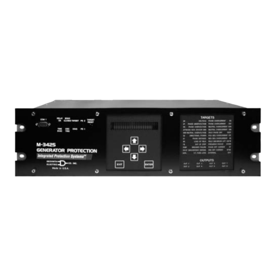
Press ENTER to bring up the main menu. Settings Press the right arrow button until SETUP UNIT appears on the top line of the The M-3425 Generator Protection Relay is shipped display. from the factory with all functions disabled (user will Press ENTER to access the SETUP only be able to enable purchased functions). - Page 93 OUT 4 OUT 6 OUT 8 Made in U.S.A. M-3931 M-3925 Human-Machine Interface Target Module Module –Optional– –Optional– Figure 3-1 M-3425 Front Panel Self-Tests POWER ON SELFTESTS TARGET XXXXXXXX BECKWITH ELECTRIC CO. 01-Jan-1998 01:05:20.000 53rd St. Substation TARGET LED Test...
- Page 94 • 27 Phase Undervoltage • 46 Neg Seq Overcurrent • 32 Directional Power • 81 Frequency • 24 Def Time Volts/Hertz • 27TN Neutral Undervoltage • 50 Inst Overcurrent • 81R Rate of Change of Freq • 24 Inv Time Volts/Hertz •...
-
Page 95: Setup System Data
M-3425 Instruction Book Level 2 access = All of level 1 privileges, Setup System Data plus read & change setpoints, target To input the data, access the SETUP SYSTEM history, set time clock. menu as follows: Level 3 access = All of level 2 privileges, Press ENTER to bring up the main menu. -
Page 96: Setpoint And Time Settings
Operation – 3 8 are form “c” contacts (center tapped “a” and “b” The Oscillograph Recorder provides comprehensive contacts). Output contacts 1–4 contain special data recording (voltage, current, and status input/ circuitry for high-speed operation and pick up about output signals) for all monitored waveforms (at 16 4 µsec faster than other contacts. -
Page 97: Status/Metering
M-3425 Instruction Book The general information required to complete the Status/Metering input data of this section includes: • Baud rate for COM1 and COM2 Monitor Status/Metering communication ports. The COM3 port does Access the STATUS menu as follows: not have a separate baud rate setting but uses the setting of COM2 (or COM1: see Press ENTER to bring up the main menu. -
Page 98: Target History
Target History • neutral current at the time of operation, • input and output status, and The M-3425 Generator Protection Relay has the ability to store the last twenty-four target conditions • a date/time tag. in a nonvolatile manner. A target is triggered whenever an output is operated (OUT1–OUT8). - Page 99 M-3425 Instruction Book This gives the phase pickup information for the specific function. TARGET 1 PHASE A=X B=X C=X TARGET 1 -CURRENT STATUS- TARGET 1 This screen shows the phase current at the time the target operated. a=0.02 b=0.03 c=0.04 TARGET 1 This screen displays the neutral current at the time the target operated.
-
Page 100: Direct Connection
Remote Operation • Interrogation and modification of setpoints • Downloading of recorded oscillograph data The M-3425 Generator Protection Relay provides three serial communication ports. Two serial • Reconfiguration of all relay functions interface ports, COM1 and COM2, are standard 9- pin, RS-232, DTE-configured ports. -
Page 101: Multiple Systems Setup
The individual addressing capability of IPScom Other communication topologies are possible using and the relay allows multiple systems to share a the M-3425 Generator Protection Relay. An Application Note, “ Serial Communication with direct or modem connection when connected via a Beckwith Electric’s Integrated Protection System... -
Page 102: Setting Up The M-3425 Generator Protection Relay For Communications
Remote Operation – 4 Setting Up the M-3425 Generator Protection Individual relay communication addresses should Relay for Communication be between 1 and 200. The dead sync time, while not critical for most communication networks, should The initial setup of the relay for communication... -
Page 103: Installation And Setup (Ipscom)
M-3425 Instruction Book Connecting the modem to the computer: The modem attached to the unit must have the following AT command configuration: a. If the computer has an external modem, use a standard straight- No Echo through RS-232 modem cable to connect the computer and modem Don’t return result code... -
Page 104: Hardware Requirements
Remote Operation – 4 Hardware Requirements Installing IPSutil™ IPScom ® will run on any IBM PC-compatible IPSutil is utility software used to program system- computer that provides at least the following: level parameters for units shipped without the M-3931 HMI Module. The IPSutil.exe file is automatically installed in the Becoware folder, along with the •... - Page 105 M-3425 Instruction Book IPScom File Comm Relay Window Help M-3425 Window User Logo Lines Relay Type / Unit Identifier File Cascade Unit Address Tile Open... Arrange Icons Close Close All Save Save As... Print Help Printer Setup Exit Alt+F4 Contents Using Help About...
-
Page 106: Overview
Since IPScom can be used with several Beckwith The Print and Printer Setup commands allow user protection systems in addition to the M-3425 to select printer options and print out all setpoint Generator Protection Relay, the format and contents... -
Page 107: Comm Menu
M-3425 Instruction Book Comm Menu If communication is established through the modem, the Initialize button should be pressed. If File Comm Relay Window Help communication cannot be established with the default string, the AT &F may be selected to initialize. -
Page 108: Relay Menu
Remote Operation – 4 Relay Menu The Setup submenu provides three commands: Setup System, Setpoints, and Set Date/Time. The Relay menu provides access to the windows The Setup System command displays the Setup used to set, monitor, or interrogate the relay. Four System dialog box (Figure 4-6) allowing the input of submenus are provided: Setup, Monitor, Targets the pertinent information regarding the system on... - Page 109 M-3425 Instruction Book The Setpoints command displays the Relay The Relay Setpoints dialog box gives access to two Setpoints dialog box (see Figure 4-7) from which additional dialog boxes: Display All and Configure. the individual relay function dialog boxes can be Choosing the Display All command button displays accessed.
- Page 110 Remote Operation – 4 All Setpoints Table Figure 4-9 All Setpoints Table Dialog Box Path: Relay menu / Setup submenu / Setpoints window/ Display All command button JUMP HOTSPOTS This window provides you with jump hotspots, identified by the hand icon, that take you to each relay dialog box and the Setup Relay dialog box.
- Page 111 M-3425 Instruction Book Configure Figure 4-10 Configure Dialog Box Path: Relay menu / Setup submenu / Setpoints window/ Configure command button JUMP HOTSPOTS This window provides you with jump hotspots, identified by the hand icon, that take you to each relay dialog box.
- Page 112 Remote Operation – 4 The Set Date/Time command (see Figure 4-11) The Monitor submenu provides access for reviewing allows the system date and time to be set, or the present status of the relay's measured and system clock to be stopped. This dialog box also calculated values, other real-time parameters and displays an LED mimic to identify when the Time conditions as well as examining real-time and...
- Page 113 M-3425 Instruction Book Target List TARGET Inputs: Outputs: Phase A Phase B Phase C Phase N Currents: -326.99A -326.99A -326.99A -326.99A Function# Status Comment Print Save Close Figure 4-12 Target Dialog Box Path: Relay menu / Targets submenu / Display window Time is displayed in milliseconds when the IRIG-B time synchronization is used.
-
Page 114: Window Menu/Help Menu
Remote Operation – 4 The Oscillograph submenu allows storing data on Currently in revision, the Help menu will enable the selected parameters for review and plotting at a user to look up information about any IPScom later time. The Setup command allows the user to menus or commands. -
Page 115: Checkout Status/Metering
M-3425 Instruction Book Checkout Status/Metering IPSCOM - [Primary Status] M-3425 VOLTAGE CURRENT POWER (var) (va) FREQUENCY V / Hz ROCOF OUTPUT INPUT BREAKER Figure 4-14 Primary Status Dialog Box Path: Relay menu/ Monitor submenu/ Primary Status window These are calculated values based on the VT and CT inputs. - Page 116 Remote Operation – 4 Phase Distance Circle Diameter 50.0 Circle Offset Circle Impedence Angle Phase Impedance -30 -20 -10 Figure 4-16 Phase Distance Dialog Box Path: Relay menu / Monitor submenu / Phase Distance window Phase Distance window shows a graphic representation of phase distance settings. Move the scope window to the right CONTROL BUTTONS Zoom In...
- Page 117 M-3425 Instruction Book Out of Step Circle Diameter 0.1 W Circle Offset 10.0 W Circle Impedance Angle 0 ° 3-End Impedance 100.0 W Positive Sequence Impedance Trip or Ended Exit ENABLED Figure 4-18 Out-of-Step Dialog Box Path: Relay menu / Monitor submenu / Out-of-Step window...
-
Page 118: Cautions
Remote Operation – 4 Function Status P: Pickup T: Tripped (21) #1 Phase Distance (51T) Inv. Time Pos. Sequence (21) #2 Phase Distance (51V) Inv. Time Phase Overcurrent (24DT) #1 Volts/Hz DEF (59) #1 Phase Overvoltage (24DT) #2 Volts/Hz DEF (59) #2 Phase Overvoltage (24IT) Volts/Hz INV (59N) #1 Neutral Overvoltage... -
Page 119: Keyboard Shortcuts
M-3425 Instruction Book 4.6 Keyboard Shortcuts Keyboard Shortcuts SYSTEM KEYS ® ® These keys can be used within Microsoft Windows and IPScom Alt-Tab To switch between applications. Ctrl-Esc To open Task List dialog box. Opens Start Menu (Win 95/98). Ctrl-Tab To switch between windows within an application. -
Page 120: Ipsutil™ Communications Software
Remote Operation – 4 4.7 IPSutil™ Communications Software IPSutility ( Relay M-3425 D-0044 V1.1.1 ) Help Comm Relay Clock Security Miscellaneous Comm Miscellaneous Setup Monitor Status RelayComm Calibration Advanced Help Comm Connect About... Exit Alt+F4 Clock Security Change Comm Access Code... - Page 121 M-3425 Instruction Book Installation and Setup • Select the correct PC communication port where the null modem cable is connected ® IPSutil™ runs with the Microsoft Windows 95 for the relay. operating system or above. Hardware requirements are the same as those stated for IPScom ®...
- Page 122 Remote Operation – 4 Clock Command Miscellaneous Menu IPSutility Miscellaneous Comm Relay Comm Clock Security Miscellaneous Help Setup When the Clock command is selected, the “Set Monitor Status Unit Date/Time” dialog box appears (See Figure Calibration 4-26). Date and Time can be changed and sent to Advanced the relay.
- Page 123 M-3425 Instruction Book Help Menu Help About... Under Help, the About... submenu provides you the information on the IPSUtil™ version numbers. COMM Baud Rate PC Port Open COM COM1 Close COM 1200 2400 Access Code Figure 4-26 Unit Date/Time Dialog Box...
- Page 124 Remote Operation – 4 SETUP Change Comm Access Code User Logo BECKWITH ELECTRIC CO. Line1: xxxx New Access Code: Line2: M-3520 xxxx Confirm New Access Code: Output Test (Relay) Cancel User Control Number: Figure 4-27 Change Communication Access OK LED Flash:...
- Page 125 M-3425 Instruction Book This Page Left Intentionally Blank 4–26...
-
Page 126: Chapter 5 Installation
Circuit Board Switches and Jumpers ..........5–10 General Information The person or group responsible for the installation If during the commissioning of the M-3425 Generator of the relay will find herein all mechanical information Protection Relay, additional tests are desired, required for physical installation, equipment ratings, Chapter 6, Testing, may be consulted. - Page 127 10.20 [25.91] 19.00 [48.26] 18.58 [47.19] 17.78 [44.65] 0.40 [1.02] x 0.27 [0.68] SLOT (4x) 2.35 [5.96] 1.35 [3.42] Standard 19" Horizontal Mount Chassis n NOTE: Dimensions in brackets are in centimeters. Figure 5-1 M-3425 Mounting Dimensions – Horizontal Chassis 5–2...
- Page 128 18.58 [43.97] [47.19] Actual 17.78 [44.65] Rear View n NOTE: Dimensions in brackets are in centimeters. RECOMMENDED CUTOUT WHEN RELAY IS NOT USED AS STANDARD RACK MOUNT Optional Vertical Mount Chassis Figure 5-2 M-3425 Mounting Dimensions – Vertical Chassis 5–3...
- Page 129 M-3425 Instruction Book 1.91 [0.99] 2.25 [4.85] [5.71] .261 [0.66] Diameter 4 Holes 8.72 [22.15] Recommended Panel Cutout Dimensions 18.21 [46.25] 2.80 2.80 [7.12] [7.12] 19.00 [48.26] 8.72 [22.15] Max. Depth of Unit: 10.50 [26.67] 6.19 [15.72] n NOTE: Dimensions in brackets are in centimeters.
- Page 130 Installation – 5 6.13 [15.57] 5.56 1.04 [14.12] [2.64] .261 [0.66] Diameter 6 Holes 8.72 [22.15] Recommended Panel Cutout Dimensions 18.50 [46.99] 2.80 2.80 [7.12] [7.12] 20.78 [52.78] 15.56 [39.52] 8.72 [22.15] 7.78 [19.76] Max. Depth of Unit: 10.50 [26.67] 2.60 [6.60] 1.14...
- Page 131 Figure 5-5 External Connections NOTES: All relays are shown in the de-energized state. Output contacts #1 through #4 are high speed operation contacts. The power supply relay (P/S) is energized when the power supply is OK. The self-test relay is energized when the relay has performed all self-tests successfully. To fulfill requirements for UL and CSA listing, terminal block connections must be made with No.
- Page 132 Three VT Wye-Wye Three VT Wye-Wye Connection - UTILITY SYSTEM Connection Ungrounded A B C A B C Other M-3425 Relays M-3921 Two VT Open-Delta Field Ground Connection Generator A B C Coupler Module M-3425 A B C A B C...
-
Page 133: Commissioning Checkout
M-3425 Instruction Book Display positive, negative and zero Commissioning Checkout sequence voltages. Press ENTER until the unit displays: During field commissioning, check the following to ensure that the CT and VT connections are correct. POS SEQUENCE VOLTAGE _____ Volts Press ENTER. After a short delay, the... - Page 134 Installation – 5 Press ENTER until the unit displays: Press ENTER for the unit to display: FIELD GND MEAS. CIRCUIT DIFFERENTIAL CURRENT 220.82 mV Press ENTER until the unit displays: Differential current should be near zero amps. If a significant amount of differential current is present, check the STATOR LOW FREQ.
- Page 135 M-3425 Instruction Book The zero sequence current should be y0 A. If a significant amount of ZERO negative or zero sequence current (greater than 25% of I ,) then either the phase sequence or the polarities are incorrect. Modify connections to obtain proper phase sequence and polarities.
-
Page 136: Circuit Board Switches And Jumpers
Installation – 5 Circuit Board Switches and Jumpers ) t l o l f ) t l a s i e l i a r t i t t i ) t l r e t i t a t s i s n i t r e r e t... - Page 137 BECKWITH CO.INC. ELECTRIC P-1629 REV. 2 BE#450-00193 Figure 5-7 M-3425 Circuit Board...
- Page 138 Testing – 6 Testing Equipment/Test Setup ................. 6–2 Diagnostic Test Procedures ..............6–6 Auto-Calibration .................. 6–11 Functional Test Procedures ..............6–15 Power On Self Tests ................6–16 21 Phase Distance ................6–17 24 Volts per Hertz, Definite Time ............6–19 24 Volts per Hertz, Inverse Time ............6–20 27 RMS Undervoltage, 3-Phase ............6–21 27TN Third-Harmonic Undervoltage, Neutral ........6–22 32 Directional Power, 3-Phase ............
-
Page 139: Equipment/Test Setup
Electronic timer accurate to at least 8 Equipment/Test Setup For relays with the 64F/B option: No calibration is necessary, as the M-3425 Generator Protection Relay is calibrated and fully Resistor decade box capable of tested at the factory. If calibration is necessary... - Page 140 Table 6-1 Functions to Disable When Testing...
- Page 141 M-3425 Instruction Book Polarity ∠ 0° Current Input 1 Voltage ∠ = 120 V ac 0° Input 1 Neutral ∠ Voltage Current Input 2 ∠ –120° = 120 V ac –120° Input 2 Neutral Voltage ∠ = 120 V ac 120°...
- Page 142 Testing – 6 Polarity 55 • 0° aø Current Input 1 • bø • cø Polarity 47 • AØ 0° Current Input 2 • BØ • CØ Figure 6-5 Current Configuration C3 6–5...
-
Page 143: Diagnostic Test Procedures
M-3425 Instruction Book Diagnostic Test Procedures The diagnostic procedures perform basic functional tests to verify the operation of the front-panel controls, inputs and outputs, and communication ports. These tests are performed in diagnostic mode, which is entered in the following manner: Press ENTER to begin main menu. -
Page 144: Input Test
Testing – 6 Choose outputs 2 through 8 by using the up arrow Press ENTER. The following is displayed: and down arrow buttons to turn all relays or outputs to the energized or ON position. Note that when INPUT NUMBER 1 each output is turned on, the appropriate red CIRCUIT OPEN OUTPUT LED turns on and stays on. -
Page 145: Status Led Test
M-3425 Instruction Book Status LED Test Target LED Test The STATUS LED TEST menu enables the user to The TARGET LED TEST menu allows the user to check the front-panel LEDs individually. check the M-3925 Target Module LEDs individually. TARGETS... -
Page 146: Button Test
EXIT is pressed. When BUTTON TEST is displayed, press the right arrow button until the following is displayed: BECKWITH ELECTRIC CO. DISPLAY TEST M-3425 "ex_io button DISP! Press ENTER. The unit will display a sequence of test characters until EXIT is pushed. -
Page 147: Com3 Test (2-Wire)
M-3425 Instruction Book Press ENTER. The following is displayed: When DISPLAY TEST is displayed, press the right arrow button until the following is displayed: COM3 ECHO TEST 2WIRE IDLING...9600, N, 8, 1 COM1 LOOPBACK TEST "COM1 com2 com3 clock! On the rear of the unit, connect a PC to the relay at terminals 3(-) and 4(+) via RS-485 converter set for 2-wire operation. -
Page 148: Clock Test
EXIT, unit will display: CLOCK TEST Auto Calibration -DONE- NOTE: The M-3425 Generator Protection Relay has been fully calibrated at the factory. NOTE: ‘80’ will be displayed in the seconds There is no need to recalibrate the unit place when the clock is stopped. -
Page 149: Third Harmonic Calibration
(THD (greater than 100 feet) to compensate for cabling less than 1%). losses from the M-3425 and the M-3921 Coupler module, and therefore should be accomplished in system, after all wiring is complete. Press ENTER. The display will show WAIT while the relay is being calibrated. - Page 150 Testing – 6 Connect the M-3921 Field Ground Coupler Set the decade box to the resistance box as shown in Figure 6-13, Field specified by the HMI, and press ENTER. Ground Coupler Calibration. When the display shows DONE press ENTER. Enter the Calibration menu in Diagnostic mode and select the FIELD_GND item Continue step 4 until the calibration is...
- Page 151 M-3425 Instruction Book M-3425 PROCESSOR Field Ground Detection Squarewave Shorted during calibration. Remove Generator before placing into service. Coupling Network M-3921 Signal Measurement Processing Discrete Capacitor to simulate Field Winding Capacitance Rear Terminal Block Pin No. Decade Box or Discrete Resistor...
-
Page 152: Functional Test Procedures
Testing – 6 Functional Test Procedures This section details test quantities, inputs and The tests are described in this section in ascending procedures for testing each relay function. The function number order as used in Chapter 2, purpose is to confirm the functions’ designated Application. -
Page 153: Power On Selftests
M-3425 Instruction Book Power On Self Tests VOLTAGE INPUTS: none CURRENT INPUTS: none Apply proper power to the power input terminals: 60 (HOT) and 61 (NEUTRAL). The unit will display: POWER ON SELFTESTS XXXXXXxxxxxxxxxxx All LEDs will turn on simultaneously for about 1 sec. The POWER and RELAY OK LEDs will remain on;... -
Page 154: Phase Distance
Testing – 6 21 Phase Distance (#1 or #2) Line to Line VOLTAGE INPUTS:Configuration V1 CURRENT INPUTS:Configuration C1 TEST SETTINGS: Diameter ohms (0.1 to 100) 1 Amp CT Rating (0.5 to 500.0) Offset ohms (–100 to 100) 1 Amp CT Rating (–500.0 to 500.0) Impedance Angle degrees... - Page 155 M-3425 Instruction Book 21 Phase Distance (#1 or #2) Line to Ground VOLTAGE INPUTS:Configuration V1 CURRENT INPUTS:Configuration C1 TEST SETTINGS: Diameter ohms (0.1 to 100) 1 Amp CT Rating (0.5 to 500.0) Offset ohms (–100 to 100) 1 Amp CT Rating (–500.0 to 500.0)
- Page 156 Testing – 6 24 Volts/Hz Definite Time (#1 or #2) VOLTAGE INPUTS: V1 CURRENT INPUTS: none TEST SETTINGS: Definite Time Pickup (100 to 200) Time Delay cycles (30 to 8160) Programmed Outputs (1 to 8) Functions 24IT, 27, 27TN Disable Function 24 DT (#1 or #2) Disable Functions 32, 59, 81, 81R...
- Page 157 M-3425 Instruction Book 24 Volts/Hz Inverse Time VOLTAGE INPUTS: V1 CURRENT INPUTS: none TEST SETTINGS: Inverse Time Pickup (100 to 200) Inverse Time Curve (1 to 4) Time Dial (curve 1) (1 to 100) Time Dial (Curves 2-4) (0.0 to 9.0)
-
Page 158: Rms Undervoltage, 3-Phase
Testing – 6 27 RMS Undervoltage, 3 Phase (#1 or #2) VOLTAGE INPUTS: Configuration V1 CURRENT INPUTS: None TEST SETTINGS: Pickup Volts (5 to 180) Time Delay Cycles (1 to 8160) Programmed Outputs (1 to 8) Functions 21, 27 (#1 or #2) Disable Functions 27TN, 32, 40 Disable... -
Page 159: 27Tn Third-Harmonic Undervoltage, Neutral
M-3425 Instruction Book 27TN Third-Harmonic Undervoltage, Neutral (#1 or #2) VOLTAGE INPUTS: Configuration V2 CURRENT INPUTS: None TEST SETTINGS: Pickup Volts (0.3 to 20.0) Time Delay cycles (1 to 8160) Undervoltage Inhibit Volts (5 to 180) Programmed Outputs ( 1 to 8) - Page 160 Testing – 6 32 Directional Power, Line to Ground, 3 Phase (#1, #2) VOLTAGE INPUTS: Configuration V1 CURRENT INPUTS: Configuration C1 TEST SETTINGS: Pickup (-3.000 to +3.000) Time Delay cycles (1 to 8160) Programmed Outputs (1 to 8) Functions 21, 32 (#1 or #2) Disable Functions 27TN, 40, 50/27 Disable...
- Page 161 The level of current at which operation is to be expected for an individual power setting is as follows: Multiply the PU pickup value (P above) by the Nominal Current previously input to the M-3425. This value is described in Section 2.1, Configuration and should be recorded on Figure A-2, Communication Data and Unit Setup Record Form.
-
Page 162: Loss Of Field
Testing – 6 40 Loss of Field (#1 or #2) VOLTAGE INPUTS: Configuration V1 CURRENT INPUTS: Configuration C1 TEST SETTINGS: Diameter ohms (0.1 to 100) Offset ohms (–50 to 50) Time Delay cycles (1 to 8160) Voltage Control Volts (5 to 180) Directional Element degrees (–13) -
Page 163: Negative Sequence Overcurrent Definite Time
M-3425 Instruction Book 46 Negative Sequence Overcurrent Definite Time VOLTAGE INPUTS:Configuration V1 CURRENT INPUTS: Configuration C1 (MODIFIED) TEST SETTINGS: Pickup Def Time (3 to 100) Time Delay cycles (1 to 8160) Programmed Outputs (1 to 8) Function 27TN, 32, 50... -
Page 164: Negative Sequence Overcurrent Inverse Time
Testing – 6 46 Negative Sequence Overcurrent Inverse Time VOLTAGE INPUTS:Configuration V1 CURRENT INPUTS: Configuration C1 (MODIFIED) TEST SETTINGS: Pickup Inv Time (3 to 100) Time Dial Setting (1 to 95) Maximum Trip Time cycles (600 to 65,500) Programmed Outputs ( 1 to 8) Function 27TN, 32, 50 Disable... -
Page 165: Instantaneous Phase Overcurrent
M-3425 Instruction Book 50 Instantaneous Phase Overcurrent VOLTAGE INPUTS: Configuration V1 CURRENT INPUTS: Configuration C1 TEST SETTINGS: Pickup Amps (1.0 to 240) Programmed Outputs (1 to 8) Functions 27TN, 32, 51T Disable Functions 51V, 87, 87GD Disable NOTE: Although no voltage input is required for the testing of the 50 function, it is suggested that Nominal Volts be applied to restrain the functions which use both voltage and current inputs for operation. -
Page 166: 50Bf Breaker Failure
Testing – 6 50BF/50BF-N Breaker Failure VOLTAGE INPUTS: Configuration V1 CURRENT INPUTS: Configuration C2 TEST SETTINGS: 50BF-Ph Pickup Amps (0.1 to 10) 50BF-N Pickup Amps (0.1 to 10) Time Delay cycles (1 to 8160) Breaker Failure Initiate (1 to 8) (1 to 6) Programmed Outputs (1 to 8) - Page 167 M-3425 Instruction Book Testing HV Breaker Failure Operation : 50BF-N DISABLED, 50BF-Ph DISABLED, Time delay set = D cycles, Input 1 in breaker closed state. With output contacts (Z) connected to the timer, initiate operation by externally shorting any ONE set of contacts (I) IN except Input 1 above.
-
Page 168: 50/27 Inadvertent Energizing
Testing – 6 50/27 Inadvertent Energizing VOLTAGE INPUTS:Configuration V1 CURRENT INPUTS: Configuration C1 TEST SETTINGS: 50 Pickup Amps (0.5 to 15) 27 Pickup Volts (40 to 130) Pickup Time Delay Cycles (1 to 8160) Dropout Time Delay Cycles (1 to 8160) Programmed Outputs (1 to 8) Functions 21, 27, 27TN... -
Page 169: 50Dt Definite Time Overcurrent For Split-Phase Differential
M-3425 Instruction Book 50DT Definite Time Overcurrent (for split-phase differential), #1 or #2 VOLTAGE INPUTS:Configuration V1 CURRENT INPUTS: Configuration C2 TEST SETTINGS: Pickup A Phase Amps (0.2 to 240) Pickup B Phase Amps (0.2 to 240.0) Pickup C Phase Amps (0.2 to 240.0) -
Page 170: Instantaneous Neutral Overcurrent
Testing – 6 50N Instantaneous Neutral Overcurrent VOLTAGE INPUTS: Configuration V1 CURRENT INPUTS: As described TEST SETTINGS: Pickup Amps (1.0 to 240) Programmed Outputs (1 to 8) Functions 51N, 87GD Disable NOTE: Although no voltage input is required for the testing of the 50N function, it is suggested that Nominal Volts be applied to restrain the functions which use both voltage and current inputs for operation. -
Page 171: Inverse Time Neutral Overcurrent
M-3425 Instruction Book 51N Inverse Time Neutral Overcurrent VOLTAGE INPUTS:Configuration V1 CURRENT INPUTS: As described TEST SETTINGS: Pickup Inv Time Amps (0.25 to 12.0) Curve Characteristic ( 1, 2, 3 or 4) Time Dial Setting (0.5 to 11.0) Programmed Outputs... -
Page 172: Inverse Time Positive Sequence Overcurrent For Stator Thermal Protection
Testing – 6 51T Inverse Time Positive Sequence Overcurrent for Stator Thermal Protection VOLTAGE INPUTS:Configuration V1 CURRENT INPUTS:Configuration C1 TEST SETTINGS: Pickup Amps (0.5 to 15.0) Time Delay (0.1 to 10.0) Programmed Outputs (1 to 8) Functions 21, 27, 32, 40 Disable Functions 50, 50/27, 51V Disable... -
Page 173: Inverse Time Phase Overcurrent With Voltage Control/Restraint
M-3425 Instruction Book 51V Inverse Time Phase Overcurrent with Voltage Control/Restraint VOLTAGE INPUTS: V1 CURRENT INPUTS: C1 TEST SETTINGS: Pickup Amps (0.5 to 12.00) Inverse Time Curve (1 to 4) Time Dial (0.5 to 11) Voltage Control Setting Volts (5 to 180) -
Page 174: Rms Overvoltage, 3-Phase
Testing – 6 59 RMS Overvoltage, 3-Phase (#1 or #2) VOLTAGE INPUTS:Configuration V1 CURRENT INPUTS:None TEST SETTINGS: Pickup Volts (5 to 180) Time Delay Cycles (1 to 8160) Programmed Outputs (1 to 8) Functions 27TN, 32 Disable Function 59 (#1 or #2) Disable NOTE: If 59 #1 and 59 #2 have different pickup settings, it would be efficient to disable the one with the lower setting first and test the higher setting operation. -
Page 175: Rms Overvoltage, Neutral Circuit Or Zero Sequence
M-3425 Instruction Book 59N RMS Overvoltage, Neutral Circuit or Zero Sequence (#1 or #2) VOLTAGE INPUTS: See Below CURRENT INPUTS: None TEST SETTINGS: Pickup Volts (5 to 180) Time Delay cycles (1 to 8160) Programmed Outputs (1 to 8) Function 27TN... -
Page 176: 60Fl Vt Fuse Loss Detection
Testing – 6 60FL VT Fuse Loss Detection VOLTAGE INPUTS: Configuration V1 CURRENT INPUTS: Configuration C1 TEST SETTINGS: Time Delay Cycles (1 to 8160) Programmed Outputs (1 to 8) Function 27, 27TN, 32, 87 Disable NOTE: It is necessary for “FL” to be designated as an initiating input (see Section 2.3, Setpoints and Time Settings) before this function can be tested. -
Page 177: Field Ground Protection
M-3425 Instruction Book 64F Field Ground Protection (#1, #2) VOLTAGE INPUTS:None CURRENT INPUTS:None TEST SETTINGS: Pickup KOhms (5 to 100) Time Delay Cycles (1 to 8160) Injection Frequency (0.10 to 1.00) Programmed Outputs (1 to 8) Function 64B Disable Disable functions as shown. See Section 3.2, Initial Setup Procedure/Settings, Configure Relay Data, for procedure. - Page 178 Once the capacitance value and the operating frequency have been determined, the actual insulation resistance can be verified by installing a variable resistor (5 to 100 KW) and discrete capacitor to the coupler module (M-3921). M-3425 60 to 100 V dc source - simulates Exciter Supply Voltage...
-
Page 179: Brush Lift Off Detection
M-3425 Instruction Book 64B Brush Lift-Off Detection VOLTAGE INPUTS:None CURRENT INPUTS:None TEST SETTINGS: Pickup (0 to 5000) Time Delay Cycles (1 to 8160) Injection Frequency (0.10 to 1.00) Programmed Outputs (1 to 8) Function 64F Disable Disable functions as shown. See Section 3.2, Initial Setup Procedure/Settings, Configure Relay Data, for procedure. -
Page 180: Out Of Step
Testing – 6 78 Out of Step VOLTAGE INPUTS:Configuration V1 CURRENT INPUTS:Configuration C1 TEST SETTINGS: Diameter ohms (0.1 to 100) Offset ohms (–100 to +100) Impedance Angle Degrees (0 to 90) Time Delay cycles (1 to 8160) Blinder Impedance ohms (0.1 to 50.0) Trip on MHO Exit See Below... -
Page 181: Frequency
M-3425 Instruction Book 81 Frequency (#1, #2, #3, #4) VOLTAGE INPUTS: Configuration V1 CURRENT INPUTS: None TEST SETTINGS: Pickup (50 to 67) Time Delay cycles (2 to 65,500) Programmed Outputs (1 to 8) Function 24, 27TN, 81R Disable NOTE: It would be efficient to disable the functions with the settings nearest to nominal frequency first (testing over or underfrequency functions). -
Page 182: Rate Of Change Of Frequency
Testing – 6 81R Rate of Change of Frequency (#1, #2) VOLTAGE INPUTS:V1 CURRENT INPUTS:None TEST SETTINGS: Pickup Hz/Sec (0.10 to 20) Time Delay Cycles (1 to 8160) Negative Sequence Voltage Inhibit (0 to 99) Programmed Outputs Output (1 to 8) Functions 24, 27TN Disable Function 81... - Page 183 M-3425 Instruction Book Negative Sequence Voltage Inhibit Test : Reset targets and apply Nominal Voltage to all three phases at a sweep rate 25% above P. Verify that the FREQUENCY/ROCOF 81/81R LED lights, or the pickup indicator operates on the computer target screen. Swing the phase angle of a phase voltage and monitor the positive and negative sequence voltage levels.
-
Page 184: Phase Differential
Testing – 6 87 Phase Differential VOLTAGE INPUTS: Configuration V1 CURRENT INPUTS: Configuration C3 TEST SETTINGS: Minimum Pickup Amps (0.2 to 3.0) Percent Slope (1 to 100) Time Delay Cycles (1 to 8160) Programmed Outputs (1 to 8) Functions 21, 32, 40 Disable Functions 46, 50, 50/27 Disable... -
Page 185: 87Gd Ground Differential
M-3425 Instruction Book 87GD Ground Differential VOLTAGE INPUTS: Configuration V1 CURRENT INPUTS: As described TEST SETTINGS: Pickup Amps (0.2 to 10) Time Delay Cycles (1 to 8160) CT Ratio Correction (0.10 to 7.99) Programmed Outputs (1 to 8) Functions 21, 46, 50/27... -
Page 186: Ext External Functions
Testing – 6 External Functions (#1 OR #2) VOLTAGE INPUTS: None CURRENT INPUTS: None TEST SETTINGS: Time Delay Cycles (1 to 8160) Programmed Outputs (1 to 8) Initiating Inputs Confirm initiating input numbers. Time Test : With output contacts (Z) connected to stop the timer, either short out input terminals designated or actually close external initiating contacts (one at a time) and start timing. - Page 187 M-3425 Instruction Book This Page Left Intentionally Blank 6–50...
- Page 188 Appendix A – Configuration Record Forms This Appendix contains photocopy–ready forms for Figure A-3, Functional Configuration Record Form recording the configuration and setting of the M-3425 reproduces the Configure Relay menus. For each Generator Protection Relay. The forms can be...
-
Page 189: Relay Configuration Table
M-3425 Instruction Book O U T Check each box applicable : (See page A-1 for information on using this table.) D Column = Function Disabled. OUTPUTS Columns =Designated function output(s) fl Column = Function blocked by fuse loss. INPUTS Columns =Designated function... - Page 190 ENTER moves to the top of the same menu but does not change menu positions. Pushing EXIT at any time will exit the display screen to the last screen containing a horizontal choice. (Return to the preceding menu). BECKWITH ELECTRIC CO. M-3425 EXIT ENTER Figure A-1 Human-Machine Interface Module The symbol ! or "...
- Page 191 M-3425 Instruction Book SETUP UNIT CLEAR OUTPUT COUNTERS " SETUP exit " logo1 logo2 OUT alrm! COMMUNICATION "targets osc_rec COMM! SOFTWARE VERSION CLEAR OUTPUT COUNTERS VERS sn access number ! PRESS ENTER KEY TO CLEAR COM1 SETUP COM1 com2 com3 com-adr! SOFTWARE VERSION D-0070V__.__.__...
- Page 192 CONFIGURE RELAYS Configuration Record Forms: Appendix – A " CONFIG sys stat! CONFIGURE RELAY VOLTAGE_RELAY ! 50/27 INADVERTANT ENRGNG 59N #1 NEUTRAL OVERVOLT 27 #1 PHASE UNDERVOLTAGE disable enable disable enable disable enable 50/27 BLOCK INPUT 27 #1 BLOCK INPUT 59N #1 BLOCK INPUT fl i6 i5 i4 i3 i2 i1 fl i6 i5 i4 i3 i2 i1...
- Page 193 M-3425 Instruction Book CONFIGURE RELAY CONFIGURE RELAY CONFIGURE RELAY " CURRENT_RELAY ! " FREQUENCY_RELAY ! "VOLTS_PER_HERTZ_RELAY! 81 #1 FREQUENCY 24DT #1 VOLTS/HZ DEF disable enable disable enable 51N NTRL OVERCURRNT INV disable enable 81 #1 BLOCK INPUT 24DT #1 BLOCK INPUT...
- Page 194 Configuration Record Forms: Appendix – A CONFIGURE RELAY CONFIGURE RELAY CONFIGURE RELAY "PHASE DISTANCE_RELAY! "LOSS_OF_FIELD_RELAY! "EXTERNAL_RELAY! 21 #1 PHASE DISTANCE 40 #1 LOSS OF FIELD EXT #1 EXTERNAL disable enable disable enable disable enable 21 #1 BLOCK INPUT 40 #1 BLOCK INPUT EXT #1 BLOCK INPUT fl i6 i5 i4 i3 i2 i1 fl i6 i5 i4 i3 i2 i1...
- Page 195 M-3425 Instruction Book SETUP SYSTEM " config SYS stat ! NOMINAL VOLTAGE 50DT SPLIT-PHASE OPERATE V.T. PHASE RATIO VOLT curr vt d_ytx rot! "mag SPLT plse seal in! " VT vt_n ct ct_n NOMINAL VOLTAGE SPLIT-PHASE OPERATE V.T. PHASE RATIO...
- Page 196 Configuration Record Forms: Appendix – A VOLTAGE RELAY 50 INST OVERCURRENT VOLT curr freq v/hz ! neg_seq INST ! 59 PHASE OVERVOLTAGE 27 PHASE UNDERVOLTAGE 50 PICKUP " PHASE_OVER PHASE_UNDER ________ Amps 59 #1 PICKUP 27 #1 PICKUP ________ Volts ________ Volts 50/27 INADVERTANT ENRGNG "INADVTNT_ENG brk_fail!
- Page 197 M-3425 Instruction Book FREQUENCY RELAY volt curr FREQ v/hz ! CURRENT RELAY 51T STATOR THERM. PROT. volt CURR freq v/hz ! " T_INV v_inv diff ! 81 FREQUENCY FREQ rcfreq 50DT DEF TIME OVERCURR 51T PICKUP " P_INST n_inst n_inv !
- Page 198 Configuration Record Forms: Appendix – A VOLTS PER HERTZ RELAY POWER RELAY V.T. FUSE LOSS RELAY volt curr freq V/HZ ! " PWR lof fuse dist! " pwr lof FUSE dist! 24 DEF TIME VOLTS/HERTZ 32 DIRECTIONAL POWER 60FL V.T. FUSE LOSS DEF_V/HZ inv_v/hz FUSE 60FL INPUT INITIATE...
- Page 199 M-3425 Instruction Book PHASE DISTANCE RELAY EXTERNAL RELAY FIELD GROUND RELAY " pwr lof fuse DIST! " rotor stator EXT ! " FIELD stator ext ! 78 OUT OF STEP EXTERNAL 64B/F FIELD GROUND dist OSTP FIELD 78 DIAMETER EXT #1 INPUT INITIATE...
-
Page 200: Appendix B-Communications
Communications: Appendix – B Appendix B–Communications Only the following MODBUS commands The M-3425 Generator Protection Relay are supported: incorporates three serial ports for intelligent, digital communication with external devices. Equipment a. read holding register (function 03) such as RTU's, data concentrators, modems, or b. - Page 201 M-3425 Instruction Book r e i i t c , 4 . c r i t i u Table B-1 Communication Port Signals NOTE: Also see Tables 5-1, 5-2 and Figure 5-7. M-3425 COM1/COM2 DB9P DB9S SGND SGND Figure B-1 Null Modem Cable: M-0423...
- Page 202 Communications: Appendix – B PC Master Echo Cancel On 25 pin or 9-25 pin Straight-Through Cable DYMEC Fiber Optic Link / Repeater D C E D T E Slave #1 Slave #2 Slave #3 Address 2 Address 3 Address 1 RS-232 RS-232 RS-232...
- Page 203 M-3425 Instruction Book RS-485 2-Wire Network Slave #1 Slave #2 Slave #3 Address 6 Address 8 Address 1 PC Master 200 Ω* B(-) A(+) Twisted RS-232 to RS-485 2-wire converter or RS-485 PC Card CAUTION: Due to the possibility of ground potential difference between units, all units should be mounted in the same rack.
-
Page 204: Appendix C-Self-Test Error Codes
Self-Test Error Codes Appendix – C Appendix C–Self-test Error Codes e t t l i a e t i l i a l i a l i a e t i r b i i t a l i a e t i l i a e t i... - Page 205 M-3425 Instruction Book r b i i t a i n r i n r e t t i n r l i a l i a l i a t r a r e t r b i i t a...
- Page 206 Self-Test Error Codes Appendix – C i l p r t n l l i i t l s i h s i h r t n t a r y l l r t n l a i i t a s i h s t l t f i...
- Page 207 M-3425 Instruction Book This Page Left Intentionally Blank C–4...
-
Page 208: Appendix D: Inverse Time Curves
This Appendix contains two sets of Inverse Time Curve Families. The first set is used for Volts per Hertz functions (Figures D-1 through D-4), and the second set is for the M-3425 functions which utilize the Inverse Time Overcurrent curves (Figures D-5 through D-12). - Page 209 M-3425 Instruction Book Figure D-1 Volts/Hz (24) Inverse Curve Family #1 (Inverse Square) D–2...
- Page 210 Inverse Time Curves: Appendix– D Figure D-2 Volts/Hz (24) Inverse Family Curve #2 D–3...
- Page 211 M-3425 Instruction Book Figure D-3 Volts/Hz (24IT) Inverse Curve Family #3 D–4...
- Page 212 Inverse Time Curves: Appendix– D Figure D-4 Volts/Hz (24IT) Inverse Curve Family #4 D–5...
- Page 213 NOTE: The above times are in seconds and are given for a time dial of 1.0. For other time dial values, multiply the above by the time dial value. Table D-1A M-3425 Inverse Time Overcurrent Relay Characteristic Curves (1 of 2) D–6...
- Page 214 NOTE: The above times are in seconds and are given for a time dial of 1.0. For other time dial values, multiply the above by the time dial value. Table D-1B M-3425 Inverse Time Overcurrent Relay Characteristic Curves (2 of 2) D–7...
- Page 215 M-3425 Instruction Book Figure D-5 Definite Time Overcurrent Curve D–8...
- Page 216 Inverse Time Curves: Appendix– D Figure D-6 Inverse Time Overcurrent Curve D–9...
- Page 217 M-3425 Instruction Book Figure D-7 Very Inverse Time Overcurrent Curve D–10...
- Page 218 Inverse Time Curves: Appendix– D Figure D-8 Extremely Inverse Time Overcurrent Curve D–11...
- Page 219 M-3425 Instruction Book 0.01 Multiple of Pickup 0.14 t=TD x 0.02 Figure D-9 IEC Curve #1 Inverse D–12...
- Page 220 Inverse Time Curves: Appendix– D 0.01 Multiple of Pickup 13.5 t=TD x M - 1 Figure D-10 IEC Curve #2 Very Inverse D–13...
- Page 221 M-3425 Instruction Book 0.01 Multiple of Pickup t=TD x Figure D-11 IEC Curve #3 Extremely Inverse D–14...
- Page 222 Inverse Time Curves: Appendix– D 1000 Multiple of Pickup t=TD x M - 1 Figure D-12 IEC Curve #4 Long-Time Inverse D–15...
- Page 223 M-3425 Instruction Book This Page Intentionally Left Blank D–16...
- Page 224 There shall be no warranties which extend beyond those contained in the Beckwith Electric Co., Inc. terms of sale. All rights reserved by Beckwith Electric Co., Inc. No reproduction may be made without prior written approval of the Company.
- Page 225 BECKWITH ELECTRIC CO., INC. 6190 - 118th Avenue North • Largo, Florida 33773-3724 U.S.A. PHONE (727) 544-2326 • FAX (727) 546-0121 E-MAIL marketing@beckwithelectric.com WEB PAGE www.beckwithelectric.com © 1998 Beckwith Electric Co. Printed in USA 800-3425-IB-02MC3 07/03...
Need help?
Do you have a question about the M-3425 and is the answer not in the manual?
Questions and answers