Advertisement
Available languages
Available languages
Quick Links
Advertisement

Related Manuals for Montarbo EARTH 218


Summary of Contents for Montarbo EARTH 218
- Page 1 manuale d’istruzioni owner’s manual...
- Page 2 ITALIANO 3 - 28 ENGLISH 29 - 54 APPENDIX 56 - 57 dati tecnici | Technical specifications Parti di ricambio | Spare parts luglio 2013 July 2013 ٥٨ .التعليمات الخاصة بالسالمة والعناية ص important safety instructions page 59 manuale d’istruzioni | Earth218 m000050 | rev.
-
Page 3: Italiano
Per qualsiasi intervento di manutenzione o riparazione, rivolgetevi ◗ subwoofer attivo alla Elettronica montarbo srl e/o a personale altamente qualificato specificamente segnalato da questa. ◗ Cavo di alimentazione • nel predisporre l’apparecchio all’utilizzo, assicurarsi che la forma e la portata della ◗... - Page 4 introduzione Earth218 è un subwoofer attivo dotato di un amplificatore di potenza il box in multistrato di betulla e i due trasduttori di grande qualità in classe d e di un dsP che permette di ottenere tutte le funzioni garantiscono grande efficienza. la grande qualità e affidabilità lo di filtraggio, equalizzazione, memorizzazione dei preset e controllo rendono un oggetto versatile sia per il palco che nei club, per la band, remoto.
- Page 5 [3] linK: connettori Xlr maschio bilanciati, in parallelo agli ingressi in [7] Connettori rJ45 delle porte data, per il collegamento all'interfaccia [5] per il collegamento di altre casse amplificate. usBnet montarbo ld2.4 (controllo remoto tramite raConls™). ® [4] aC line in: Connettore di ingresso alimentazione. È un connettore usare normali cavi etHernet a 8 poli (Cat5 o superiore).
- Page 6 Comandi dsP X-OVER OUT L VOL. NEUTRIK sig clip thw prot IN L PUSH [P1] [UP] [P2] NEUTRIK [P3] Both = Enter Preset [P4] [DOWN] [P0] User DOWN LINK R NEUTRIK [A] led verde 'sig' (signal): indica la presenza di segnale in ingresso. [B] led rosso 'clip' : indica la saturazione (clipping) dello stadio di ingresso del dsP interno.
- Page 7 importante COLLEGAMENTO ALLA RETE • accertarsi che l’interruttore di rete sia in posizione '0' (spia luminosa spenta). • Accertarsi che la tensione di rete corrisponda a quella indicata sul pannello. • Collegare il cavo di alimentazione ad una presa di corrente dotata di contatto di terra di sicura efficienza.
- Page 8 importante 20 mm CABLAGGIO DEL CAVO DI ALIMENTAZIONE SUL CONNETTORE 8 mm powerCON (FORNITO CON L’APPARECCHIO). ® l’assemblaggio del cordone di rete deve essere effettuato da personale specializzato seguendo le regole impiantistiche nazionali. spelare il cavo per una lunghezza di 20 mm ed ogni singolo filo per una fili cavo lunghezza di 8 mm.
- Page 9 • Se il mixer ha uscite bilanciate XLR: utilizzare dei normali connettori XLR bilanciati. • Se il mixer ha uscite sbilanciate XLR e non è un Montarbo: è bene accertarsi che le uscite Xlr del mixer siano sbilanciate a norme ieC 268 e cioè...
- Page 10 importante CABLAGGIO DEL SISTEMA CURA E MANUTENZIONE DEL PRODOTTO Collegamento alla rete • Evitare di esporre le casse alla radiazione solare diretta, ad eccessive - accertarsi che la tensione di alimentazione corrisponda a quella indicata vibrazioni e ad urti violenti. sul pannello.
- Page 11 è nel rifasamento fra subwoofer e satellite. nella il metodo più semplice sta nel controllare i livelli della catena del segnale. regione di cross-over (100/120Hz per i sistemi montarbo ) si potrebbe Partendo dal canale del mixer bisogna impostare i controlli (gain ed ®...
- Page 12 esempio di collegamento mixer l / r outputs ➔ subwoofer l / r inputs subwoofer X-oVer l / r outputs ➔ inputs of the two self-powered loudspeakers VOL. VOL. LINK SUB OUT LINK SUB OUT prot prot clip clip Preset Preset User User...
- Page 13 È necessario l'uso dell'interfaccia usB opzionale ld2.4. sia al minimo. mediante essa è possibile controllare fino a 10 diffusori attivi montarbo ® Per evitare sbalzi di segnale, effettuare i collegamenti, poi accendere prima delle serie Full, sPot, Wide e mol, in qualsiasi combinazione.
- Page 14 Attenzione: installare la versione del software RACon™ (RAConLS™) specifica per l'uso con i diffusori attivi serie FULL, SPOT, WIDE e MOL. Non utilizzare versioni previste per altri apparecchi Montarbo ® inserendo nel lettore del personal computer il Cd fornito con l'interfaccia ld2.4, viene mandato in esecuzione automatica un programma di...
- Page 15 software raConls ™ INSTALLAZIONE seguire le indicazioni del setup wizard per personalizzare l'installazione. Cliccate su Next. Comparirà la schermata seguente, in cui si chiede di accettare il contratto di licenza. se si vuole continuare l'installazione, selezionare "I accept the agreement", quindi cliccare Next. Earth218 | manuale d’istruzioni...
- Page 16 apparirà questa schermata, in cui si chiede dove si vuole installare il programma. scrivere il percorso su cui copiare i file oppure lasciare la destinazione predefinita. nella schermata successiva, è possibile selezionare il nome del gruppo di programmi che verrà creato nel menu start. manuale d’istruzioni | Earth218...
- Page 17 nella schermata successiva, scegliere se creare o no le icone aggiuntive sul desktop e/o nella barra di avvio veloce di Windows ® una volta selezionate le varie opzioni, il programma è pronto a copiare i file sul PC. Cliccate Install e il programma RAConLS™ verrà installato sul PC.
- Page 18 dopo il programma raConls™, il processo di installazione continua con l'installazione del driver usB dell'interfaccia usBnet ld2.4, necessaria per comunicare con i sistemi attraverso la linea seriale rs485Fd. Durante l'installazione il cavo USB DEVE RIMANERE SCOLLEGATO dal PC. durante l'installazione del driver usB, il sistema operativo mostrerà un messaggio relativo al test facoltativo Windows logo.
- Page 19 Con la schermata successiva l'installazione del programma viene ultimata. Ora è possibile collegare il cavo USB e l'interfaccia LD2.4. Il PC riconosce il nuovo hardware e ne effettua la registrazione nel sistema. il software è gia presente sul PC, quindi non è necessario eseguire la ricerca: selezionare No, non ora e cliccare Avanti.
- Page 20 Comparirà la schermata seguente, in cui il sistema operativo chiede dove è il software da installare: lasciare la selezione consigliata (automatico) e cliccare Avanti. Come in precedenza, saltare il messaggio Windows logo cliccando su Continua. se richiesto, selezionare montarbo usBnet e cliccare Avanti. manuale d’istruzioni | Earth218...
- Page 21 Earth218 | manuale d’istruzioni...
- Page 22 è scollegata nella casella dei messaggi viene indicato NoDevice. in questo caso inserire il cavo usB e l'interfaccia ld 2.4 ed attendere la comparsa della scritta Montarbo USBNet e successivamente Status OK. manuale d’istruzioni | Earth218...
- Page 23 se il programma è già stato utilizzato precedentemente, con una certa configurazione di diffusori, nella finestra in alto a sinistra comparirà la lista dei diffusori registrati e nella parte inferiore dello schermo le finestre corrispondenti ai vari diffusori. nel caso di primo utilizzo del programma, o nel caso in cui sia stata cambiata la configurazione dei diffusori, occorre procedere alla loro registrazione, in modo che il programma raConls™...
- Page 24 ™ PREPARAZIONE DELLA LISTA DEI DIFFUSORI ogni diffusore montarbo selle serie Full, sPot e Wide ha, incorporato nel software del dsP interno, un identificativo (nome) univoco, nel formato esadecimale 'Hxxxxxxxxxxxxxxx' che lo distingue da tutti gli altri (un 'numero di matricola' digitale).
- Page 25 software raConls ™ FINESTRA COMANDO CONTROLLER IMPORTANTE: i diffusori collegati sono visualizzati a coppie sinistro / destro (l/r). in seguito è descritto come sia possibile il comando contemporaneo dei due diffusori di una coppia. l'ordine in cui sono visualizzati e quindi suddivisi in coppie corrisponde all'ordine in cui sono stati registrati premendo i tasti uP e doWn.
- Page 26 Questa è la finestra di comando, dove è possibile intervenire su tutti i parametri modificabili. a sinistra compare un indicatore di livello del segnale di ingresso. l'accensione dell'indicatore rosso in alto indica la saturazione del convertitore a/d. nel caso di due diffusori che formano una coppia (come descritto nella pagina precedente) l'indicatore di livello sarà...
- Page 27 a destra in alto compare l'indicazione della temperatura ambiente (ta1) e degli amplificatori di potenza (tf1). nel caso di due diffusori che formano una coppia le temperature indicate saranno 4: ta1 e tF1 per il primo diffusore e ta2 e tf2 per il secondo. a destra compare la finestra di controllo del volume (attenuazione di uscita) È...
- Page 28 0 (user Preset), all'accensione sarà attivo il preset modificato. eventuali nuovi preset che saranno resi disponibili da montarbo potranno essere caricati salvandoli sul PC e richiamandoli come descritto precedentemente. manuale d’istruzioni | Earth218...
-
Page 29: English
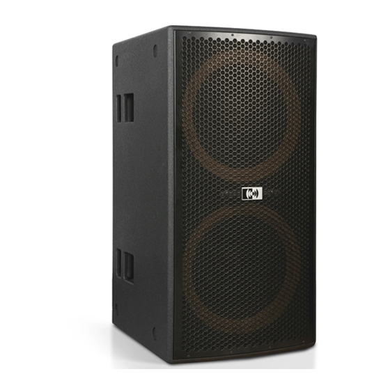
For maintenance ◗ active subwoofer and servicing always refer to the official Elettronica Montarbo srl Distributor in your Country or to qualified personnel specifically authorised by the Distributor. ◗ Power supply cable •... - Page 30 introduction Earth218 is an active subwoofer with a class-d amplifier and a transducers let earth218 be a high efficiency bass cabinet. its great built-in dsP which provides all filtering, equalization, Preset memory quality and reliability let it be a versatile device, suitable for several and remote control functions.
-
Page 31: Controls And Connections
(sub and satellites simultaneously). [3] linK: Xlr male balanced connectors, in parallel with inputs in [5], [7] rJ45 sockets of the two data ports, to connect a montarbo ld 2.4 to connect additional powered speakers. usBnet interface. use standard 8 poles etHernet cables (Cat5 or [4] aC line in: ac line input connector. - Page 32 dsP controls X-OVER OUT L VOL. NEUTRIK sig clip thw prot IN L PUSH [P1] [UP] [P2] NEUTRIK [P3] Both = Enter Preset [P4] [DOWN] [P0] User DOWN LINK R NEUTRIK [A] Green led 'siG' (signal): it lights up when an input signal is detected. [B] red led 'CliP': it lights up when a clipping (excess of signal level) is detected in the input stage of the internal dsP.
- Page 33 important AC MAINS CONNECTION • Make sure the mains power switch is off ('0'). • Check that mains voltage corresponds to the voltage indicated on the panel. • Use only the factory supplied mains cable or, if a different plug style is needed, a suitable cable with a ground connection and marked with the safety approvals valid in the country of use.
- Page 34 important 20 mm WIRING OF THE POWER CABLE FOR THE powerCON ® 8 mm (SUPPLIED WITH THE UNIT). the power cord assembly must be made by a qualified technician in compliance with the national regulations in force for electrical systems. strip the cable for 20 mm of length and strip each wire for 8 mm of length.
- Page 35 • If the mixer has XLR unbalanced outputs: in this case, unless using a montarbo mixer, make sure that the Xlr outputs on the mixer are unbalanced to ieC 268 standard 1 = Gnd, 2 = Hot, 3 = Gnd.
- Page 36 important SySTEM WIRING PRODUCT CARE AND MAINTENANCE AC mains connection • Never expose the enclosures to direct sunlight, excessive vibrations or - make sure that the ac line voltage value corresponds to the one indicated mechanical shocks. on rear panel. •...
- Page 37 PFl meter will never (or in the cross-over region (100/120 Hz in montarbo systems) the physical only occasionally) indicate more than 0dB.
- Page 38 Connection example mixer l / r outputs ➔ subwoofer l / r inputs subwoofer X-oVer l / r outputs ➔ inputs of the two self-powered loudspeakers VOL. VOL. LINK SUB OUT LINK SUB OUT prot prot clip clip Preset Preset User User Both = Enter...
- Page 39 With it the user may control any combination of up to 10 active speakers the mixer's master faders are at their minimum position.to avoid signal system of the montarbo Full, sPot, Wide and mol series. peaks, first make the connections, then switch on the mixer first and after the active speakers.
- Page 40 Caution: install the (RAConLS) version of the RACon™ software program specifically intended for use with the FULL, SPOT, WIDE and MOL series of active loudspeakers. Do not use other versions specified for other Montarbo products. ® insert the Cd that comes with the ld2.4 interface unit into the computer drive.
- Page 41 raConls software ™ INSTALLATION Follow the instructions provided by the setup wizard to customize the installation Click on the Next button. the following window will open, asking you to accept the license agreement. if you want to continue the installation process, click on 'I accept the agreement', and then, click on 'Next'.
- Page 42 this window will open, asking which folder you want the program installed into. Write the folder name, or browse to search for it, or simply accept the default folder. the following window allows you to select the program's group name in the start menu. owner’s manual | Earth218...
- Page 43 the following window allows you to create icons for the program on the desktop and/or in the Quick launch bar. once the various options have been selected, the installation program is ready to copy the program's files to the PC. Click Install botton to let the RAConLS™...
- Page 44 after completing the installation of the raConls™ program, the process will continue with the usB driver for the usBnet – ld2.4 interface, required for the PC to communicate with the speaker's dsP controllers via the rs485Fd serial interface. During the installation the USB cable MUST BE UNPLUGGED FROM THE PC.
- Page 45 the following window will display when the raConls™ program setup process has been completed. Now it is possible to plug in the USB cable and the LD2.4 interface. the PC will detect the new hardware and will add it to the system's registry.
- Page 46 (recommended) and click next. as you did previously, ignore the Windows logo compatibility message by clicking on Continue anyway. if requested, select Montarbo USBNet and click on next. owner’s manual | Earth218...
- Page 47 Montarbo USBNet are ready for use. Earth218 | owner’s manual...
- Page 48 PC and wait for the search… message to disappear. the message window will show Montarbo USBNet for a short time, then Status OK. owner’s manual | Earth218...
- Page 49 if the program has been previously used with a certain configuration of speakers, the upper- left window will display the list of the registered speakers, and the lower part of the screen will display a group of windows corresponding to the above speakers. the first time the program is used and each time the configuration of the speakers is altered it will be necessary to register them in the program's database, so that the raConls™...
- Page 50 ™ BUILDING THE SPEAKER'S LIST each speaker system in the montarbo's Full, sPot, Wide and mol series has, permanently written in the internal dsP's software, a unique id (name) in the hexadecimal format 'Hxxxxxxxxxxxxxxx', that will distinguish it from all the others (a digital 'serial number').
- Page 51 raConls software ™ MAIN CONTROLLER WINDOW IMPORTANT: the networked speakers are displayed as left / right couples. the two speakers in a l/r couple may be linked together and both controlled at the same time, as will be described in the following paragraphs.
- Page 52 this is the command window from which it is possible to work on all modifiable parameters. at the left a stereo bar-graph indicates the input levels. the red indicator light will go on when an a/d converter overload is detected. the equalizer section includes 10 fully-parametric filters that make it possible to adjust the system's frequency response, to adapt it to a particular room's acoustics or to obtain a personalized response.
- Page 53 on the upper-right side of the windows are displayed both the ambient (external) temperature (ta1) and the power amplifier’s temperature (tf1). on the right side there is displayed the volume control (output attenuation) window. it is possible to adjust the volume with the outattn knob. the attenuation range is from 0.0 to -32.0 dB, with 0.5 dB increments.
- Page 54 0 (user Preset), it will be the default preset at switch-on. any future updated preset which may be made available from montarbo will be loaded the same way: first saved on the PC as preset files, then recalled and stored as described above.
- Page 55 APPENDIX dati tecnici Technical specifications Parti di ricambio Spare parts ٥٨ .التعليمات الخاصة بالسالمة والعناية ص important safety instructions page 59 Earth218 | appendix...
-
Page 56: Appendix
2 x 18” neodymium woofers with 4” voice coil. Custom-designed BuILT-IN AmPLIFIEr class-d power units, 3400 W eiaJ BuILT-IN DSP montarbo ® , 24 bit conv. mANAGEmENT FuNcTIONS Filtering, eQ, delay, limiting, diagnostic, 5 presets, 1 of which custom-programmable, remote control by PC by means of usB interface, ld2.4 (optional device) -
Page 57: Appendix
Parti di ricambio | Spare parts [B010023] [A300A10] [D20E218] [D52E218] [D60002] [D00SPKD] [D00mOLJ] A300A10 D52E218 Woofer da 18" Pannello controlli e connessioni + amplificatore di potenza 18" woofer Control panel + power amplifier D20E218 D60002 Griglia in acciaio Power module Steel grille Power module B010023... - Page 58 هام! التعليمات الخاصة بالسالمة والعناية العربية !تحذير !إنذار من أجل حمايتك أنت وال آ خرين ومن أجل عدم حدوث إلغاء لشهادة الضمان الخاصة هذا المنتج ال يحوي قطع غيار خاصة تفيد المستخدم. من أجل تفادي حدوث أي بهذا المنتج٬ يرجى ق ر اءة هذا الجزء من دليل الستخدام بعناية قبل ال� رش وع بتشغيل صدمة...
-
Page 59: English
For maintenance and servicing always refer to the official Montarbo Distributor in your Country or to qualified personnel specifically authorized by the Distributor. This product has been designed and manufactured for being operated as active speaker system in the applications typical of a sound reinforcement system or a sound recording system. - Page 60 Information on Disposal for Professional users In the European Union | if the product is used for business purposes and you want to discard it: please contact your montarbo ® dealer who will inform you about the take-back of the product. You might be charged for the costs arising from take-back and recycling.
Need help?
Do you have a question about the EARTH 218 and is the answer not in the manual?
Questions and answers