
Related Manuals for Hach PHOSPHAX indoor sc


Summary of Contents for Hach PHOSPHAX indoor sc
- Page 1 DOC026.53.00026 PHOSPHAX sc, PHOSPHAX indoor sc USER MANUAL 04/2013, Edition 6 PHOSPHAX sc, PHOSPHAX indoor sc © HACH Comp., 2006–2010; 2012, 2013. All rights reserved. Printed in Germany. sd/sk...
-
Page 3: Table Of Contents
Table of Contents Section 1 Specifications ......................5 Section 2 General Information ....................9 2.1 Safety information ........................9 2.1.1 Use of hazard information ....................9 2.1.2 Precautionary labels ......................10 2.1.3 Change instrument labels ....................11 2.2 Product overview ........................11 Section 3 Installation ...................... - Page 4 Table of Contents Section 7 Troubleshooting ....................47 7.1 Troubleshooting the controller ....................47 7.2 Troubleshooting the analyzer ....................47 7.2.1 LED status ........................47 7.2.2 Error messages ........................47 7.2.3 Warnings .........................49 Section 8 Replacement Parts and Accessories ..............51 8.1 Standards and reagents ......................51 8.2 Analyzer accessories ........................51 8.3 Mounting hardware ........................51 8.4 Replacement parts ........................51...
-
Page 5: Section 1 Specifications
(Figure 1 on page Figure 2 on page PHOSPHAX indoor sc: (W × H × D) 540 × 720 × 370 mm (21,25 × 28,35 × 14.5 in.) Data and power cable lengths 2 m (80 in.) (from edge of enclosure) -
Page 6: Specifications
Specifications Figure 1 Instrument dimensions PHOSPHAX sc... - Page 7 [4094 in] 237 mm [9.33 in] 40 mm [1.57 in] 850 mm [33.15 in] 390 mm 540 mm [15.35 in] [21.26 in] 720 mm [28.35 in] 280 mm 466 mm [11.02 in] [18.11 in] Figure 2 Instrument dimensions PHOSPHAX indoor sc...
- Page 8 Specifications...
-
Page 9: Section 2 General Information
Section 2 General Information 2.1 Safety information Please read this entire manual before unpacking, setting up or operating this equipment. Pay attention to all danger and caution statements. Failure to do so could result in serious injury to the operator or damage to the equipment. Make sure that the protection provided by this equipment is not impaired, do not use or install this equipment in any manner other than that specified in this manual. -
Page 10: Precautionary Labels
General Information 2.1.2 Precautionary labels Read all labels and tags attached to the instrument. Personal injury or damage to the instrument could occur if not observed. A symbol, if noted on the instrument, will be included with a danger or caution statement in the manual. -
Page 11: Change Instrument Labels
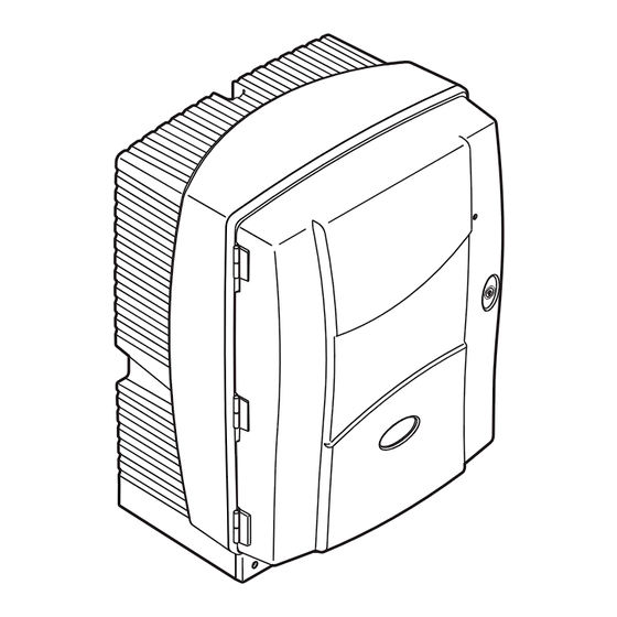
General Information 2.1.3 Change instrument labels Several safety labels (3 in the analytical section) are applied to the instrument. If necessary, apply the correct language label over the existing safety labels. 2.2 Product overview The PHOSPHAX sc (Figure Figure 4) measures 3–... -
Page 12: General Information
General Information Figure 4 PHOSPHAX indoor sc enclosure LED for operating state. Refer to Door lock Rating plate with model number, Table 7 on page 47 for more serial number, voltage and information. frequency information, and power consumption information... -
Page 13: Section 3 Installation
Section 3 Installation DANGER Only qualified personnel should conduct the tasks described in this section of the manual. CAUTION The enclosure may tip forwards if it has not been fixed in place. Only open the enclosure if the enclosure is properly mounted. -
Page 14: Unpack The Instrument
Installation 3.2 Unpack the instrument CAUTION Pay attention to the weight (approximately 31 kg) of the instrument. Do not try to carry the instrument without assistance. Use only suitable lifting tackle for transport. Open the shipping container while it is on its end and then slide the analyzer out of the cardboard. - Page 15 Installation 4. Attach the enclosure to the fastening bracket. 5. Attach the angle bracket on the enclosure to the wall. Figure 5 Bracket dimensions for wall mounting...
- Page 16 Installation Figure 6 Wall mounting the analyzer Washer, M5 (4X) Screw, customer supplied Socket head cap screw, M5 X 8 (2X) Socket head cap screw, M5 X 40 (2X) Angle bracket Fastening bracket...
-
Page 17: Initial Instrument Setup
Installation 3.4 Initial instrument setup 3.4.1 Open the enclosure DANGER To reduce the risk of electrical shock, make sure that no water can enter the enclosure or come into contact with circuit boards. CAUTION The enclosure may tip forwards if it has not been fixed in place. - Page 18 Installation Figure 8 Open the PHOSPHAX indoor sc enclosure Latches Lock with key Door hook...
-
Page 19: Remove The Shipping Transport Locks
Installation 3.4.2 Remove the shipping transport locks Prior to system start-up, the shipping transport locks must be removed from the sc analyzer. CAUTION The enclosure may tip forwards if it has not been fixed in place. Only open the enclosure if the enclosure is properly mounted. -
Page 20: Installation Of The Collecting Tray
Installation 3.4.3 Installation of the collecting tray Figure 10 Remove the compressor transport lock Compressor transport lock Protective cover for compressor Cable tie Fan locking screw Compressor The compressor, compressor transport lock, and cable tie only apply to sc analyzers that operate using the Filter Probe sc. - Page 21 Installation CAUTION The enclosure may tip forwards if it has not been fixed in place. Only open the enclosure if the enclosure is properly mounted. 1. Open the enclosure door and secure with the door hook. 2. Slide the collecting tray into the bottom of the enclosure (Figure 11).
-
Page 22: Connect The Humidity Sensor
Installation 3.4.4 Connect the humidity sensor CAUTION The enclosure may tip forwards if it has not been fixed in place. Only open the enclosure if the enclosure is properly mounted. 1. Remove power from the instrument. 2. Open the enclosure door and secure with the door hook. 3. -
Page 23: Connect The Sample Supplies And Drain
Installation 3.4.5 Connect the sample supplies and drain Before connecting tubing or cables, determine the option number that corresponds the system configuration. Refer to Table 1. Based on the option number, determine the sealing plug that will be used to seal the enclosure openings, refer to Table When the option number is determined, refer to Appendix A... -
Page 24: Electrical Installation
Installation Figure 13 Sealing plug types Sealing plug type 1 Sealing plug type 2 Sealing plug type 3 Electrical installation DANGER High voltage wiring connections are present under the protective cover. The protective cover must remain in place unless a qualified installation technician is installing wiring for the Filter Probe sc or the heated drain. -
Page 25: Electrostatic Discharge (Esd) Considerations
Installation 3.5.1 Electrostatic Discharge (ESD) Considerations Important Note: To minimize hazards and ESD risks, maintenance procedures not requiring power to the analyzer should be performed with power removed. Delicate internal electronic components can be damaged by static electricity, resulting in degraded instrument performance or eventual failure. -
Page 26: Insert Tubing And/Or Cables
Installation 3.5.3 Insert tubing and/or cables Guide the tubing or cables through Push the plug from the top onto the Pull down the plug with the tubing the enclosure openings tubing or onto the cable. or the cables. Seal any unused (Figure 15). -
Page 27: Connect The Optional Heated Drain
Installation 3.5.5 Connect the optional heated drain CAUTION The enclosure may tip forwards if it has not been fixed in place. Only open the enclosure if the enclosure is properly mounted. DANGER Disconnect power from the sc analyzer at the sc1000 before removing the protective covers in the analyzer. - Page 28 Installation Figure 16 Connect the Filter Probe sc and optional heated drain Bottom panel cover Filter Probe sc air tube (white) Protective cover Filter Probe sc ground wire Heated drain (optional) power connector 10 Filter Probe sc data cable connector Filter Probe sc power connector 11 Filter Probe sc power cable connector Earth ground wire terminal strip...
-
Page 29: Installation Of Reagents
Installation Installation of reagents CAUTION The enclosure may tip forwards if it has not been fixed in place. Only open the enclosure if the enclosure is properly mounted. DANGER Potential danger in the event of contact with chemical/biological materials. Handling chemical samples, standards and reagents can be dangerous. - Page 30 Installation Figure 17 Chemicals and reagents in the PHOSPHAX sc (section 8.1 on page Connection to colorimeter (detector) Reagent Drain Cleaning solution Sample line...
-
Page 31: Supply Power To The Analyzer
Installation Supply power to the analyzer DANGER Only connect the PHOSPHAX sc to the sc1000 power supply when the instrument is completely wired internally and it is correctly earthed. DANGER Always connect a ground fault interrupt circuit (GFIC) or a residual current circuit breaker (trigger current maximum at 30 mA) between the main power supply and the sc1000. -
Page 32: Connect The Data Network
Installation Figure 18 Connect the PHOSPHAX sc to the sc1000 power supply Data network connector Power connectors 3.8 Connect the data network Refer to the sc1000 controller user manual for more information on connecting the Data Network (item 1, Figure 18). -
Page 33: Section 4 System Startup
Section 4 System Startup 4.1 Initializing the instrument Important Note: The instrument only can work correctly if it is at operating temperature. Let the instrument warm up for a minimum of an hour so the inside of the enclosure, chemicals and electrode are at operating temperature. - Page 34 System Startup...
-
Page 35: Section 5 Operation
Section 5 Operation The PHOSPHAX sc can only be operated with an sc1000 controller. Refer to the sc1000 user manual for more information. An LED on the door (works with door open and closed) indicates the current operating state. Refer to the sc1000 User Manual and section 7.2.1 on page 5.1 Sensor diagnostics menu SELECT PHOSPHAX sc (if more than one sensor or analyzer is attached) - Page 36 Operation 5.2 Sensor setup menu (continued) CONFIGURE (continued) MEASURING Enter how often measurements are to be taken. ATTENTION with filtration probe and 5min SET INTERVAL operation: increased pump speed in the filtration probe, annual filtration probe maintenance is necessary instead of every 2 years. WET/DRY, decides if the cuvette is empty (DRY) or filled (WET) between measurements at SET TO measurement intervals that are equal or greater than 10 minutes.
- Page 37 Operation 5.2 Sensor setup menu (continued) CONFIGURE (continued) DEFAULT SETUP Prompt as to whether the factory settings are to be re-applied. LAST CHANGE Indication of the last change to a setting on the configuration menu. MAINTENANCE INFORMATION LOCATION 1 Indication of measuring location 1 LOCATION 2 Indication of measuring location 2 (on two-channel version) TYPE...
- Page 38 Operation 5.2 Sensor setup menu (continued) MAINTENANCE (continued) MAINT. COUNTER Counter for reagent and consumables OPERATING HOURS Displays the instrument's operating hours. REAGENT Displays the current level of the reagent. CLEANING SOL. Displays the current level of the cleaning solution. AIR FILTER PADS Days left until the next air filter change/clean.
-
Page 39: System Setup Menu
Operation 5.2 Sensor setup menu (continued) MAINTENANCE (continued) PREPUMPING PREPUMP ALL All liquids are pre-pumped in succession. PREPUMP REAG. The reagent is pre-pumped. PREPUMP CLEAN. The cleaning solution is pre-pumped. PREPUMPING Only if filtration probe is registered: The filtration probe and modules are bled and PROBE pre-pumped. -
Page 40: Measurement Process
Operation 5.4 Measurement process Note: Make sure that all solutions are available to avoid incorrect measurements. After start up, the instrument needs to warm up to automatically initalize the measurment process. This process takes approximately 15 minutes when the instrument temperature is >15 °C (>59 °F). -
Page 41: Section 6 Maintenance
Section 6 Maintenance DANGER Only qualified personnel should conduct the tasks described in this section of the manual. DANGER Potential danger in the event of contact with chemical/biological materials. Handling chemical samples, standards and reagents can be dangerous. Familiarize yourself with the necessary safety procedures and the correct handling of the chemicals before the work and read and follow all relevant safety data sheets. -
Page 42: Fuse Replacement
Maintenance To stop the cooling fan: 1. From the MENU select SENSOR SETUP>PHOSPHAX SC and press ENTER. 2. Select MAINTENANCE>TEST/MAINT>AIR FILTER PADS and press ENTER. 3. Select START and press ENTER. The process is started and the cooling fan stops. Important Note: Open the instrument door to prevent overheating. -
Page 43: Routine Maintenance Schedule
Maintenance 6.2 Routine maintenance schedule The maintenance schedule is given for standard applications. Deviant applications may cause different maintenance intervals. Table 4 Routine maintenance schedule Description 3 months 6 months 12 months 24 months Check measurement chamber and history of amplification (event log). - Page 44 Maintenance 5. Enter the number of measurements which should be used for the validation measurements. (Default value: 3; value range: 2 to 10) 6. Select START after adjusting both parameters and the analyzer is going into the service state. The remaining time is displayed in seconds.
-
Page 45: Shut The Analyzer Down
Maintenance Figure 19 Modification of PHOSPHAX sc Overflow vessel Valve block Fitting of sample tube Sample tube Blind plug 6.4 Shut the analyzer down No special measures are necessary for taking out of operation for a short period (up to a few days in frost-free ambient conditions). Important note: If the power supply to the controller is interrupted, frost damage may occur. -
Page 46: Scheduled Maintenance
Maintenance Use the following procedure if the instrument is to be taken out of operation for an extended period, or in the case of risk of frost. 1. Immerse the tubing for reagent and cleaning solutions in distilled water. 2. On the controller TEST/MAINT menu, start a cleaning cycle with distilled water using the FLUSHING. -
Page 47: Section 7 Troubleshooting
Section 7 Troubleshooting 7.1 Troubleshooting the controller If entries are only implemented with a delay or are not accepted for a short time, the delay may be caused by a busy data network. Refer to the troubleshooting section in the sc1000 User Manual. If, in normal operation, problems occur that are apparently caused by the controller, restart the system. - Page 48 Troubleshooting 7.2.2 Error messages (continued) Instrument Error displayed Cause Solution Reset error reaction Instrument cannot heat interior Instrument goes adequately. Reset error NO HEAT UP into the service Close instrument, check heating (internal temp manually state <20°C (68°F) for 30 min) Manual reset or Service state, Instrument interior...
-
Page 49: Warnings
Troubleshooting 7.2.2 Error messages (continued) Instrument Error displayed Cause Solution Reset error reaction Photometer signal too high (1 Reset error PHOTO LEVEL channel, 2 channel Continued manually or HIGH / PHOTO operation , Contact service measurement automatic if level is LEVEL2 HIGH depending on OK again... - Page 50 Troubleshooting 7.2.3 Warnings (continued) Instrument Warning displayed Cause Solution Reset warning reaction Trigger cleaning (several times). Manually clean Photometer signal low photometer. If this action PHOT LEVEL LOW / Continued (dependent on chanel if 2 solves the problem, Automatic PHOT LEVEL2 LOW measurement chanel mode is used) .
-
Page 51: Section 8 Replacement Parts And Accessories
Section 8 Replacement Parts and Accessories 8.1 Standards and reagents Cat. No. Cat. No. Description EU customer US customer Cleaning solution, PHOSPHAX sc (1 L) for all measurement ranges LCW870 28253-52 Reagent, PHOSPHAX sc (2 L) for all measurement ranges LCW869 28252-54 8.2 Analyzer accessories... - Page 52 Replacement Parts and Accessories 8.4 Replacement parts (continued) (Refer to Figure 20 on page 54–Figure 24 on page Item Description 1 Cat. No. Set of filter pads (2 pieces) LZY154 Clamping lock for sc analyzer LZY147 Fence, includes screws M3 x 6 LZY157 Compressor switchable 115 V/230 V LZY149...
- Page 53 Replacement Parts and Accessories 8.4 Replacement parts (continued) (Refer to Figure 20 on page 54–Figure 24 on page Item Description 1 Cat. No. Piston pump for sc analyzer LZY177 Cover for reagent pump LZY178 Set of fittings, 1.6 mm, (4 pieces) LZY192 Tubing, 1.6 mm (2 m), sc analyzer LZY194...
- Page 54 Replacement Parts and Accessories Exploded view drawings Figure 20 Analyzer enclosure PHOSPHAX sc...
- Page 55 Replacement Parts and Accessories Figure 21 Analyzer enclosure PHOSPHAX indoor sc...
- Page 56 Replacement Parts and Accessories Figure 22 Analyzer panel overview...
- Page 57 Replacement Parts and Accessories Figure 23 Analyzer panel front view details...
- Page 58 Replacement Parts and Accessories Figure 24 Analyzer panel back view details...
-
Page 59: Section 9 Contact Information
HACH Company Repair Service in the Repair Service in Canada: Repair Service in World Headquarters United States: Latin America, the Hach Sales & Service Caribbean, the Far East, P.O. Box 389 HACH Company Canada Ltd. Indian Subcontinent, Africa, Loveland, Colorado... - Page 60 Contact Information HACH LANGE D.O.O. ΗΑCH LANGE E.Π.Ε. HACH LANGE D.O.O. HACH LANGE MAROC SARLAU Fajfarjeva 15 Αυλίδος 27 Ivana Severa bb SI-1230 Domžale GR-115 27 Αθήνα HR-42 000 Varaždin Villa 14 – Rue 2 Casa Tel. +386 (0)59 051 000 Τηλ.
-
Page 61: Section 10 Limited Warranty
In the event that a defect is discovered during the warranty period, Hach Company agrees that, at its option, it will repair or replace the defective product or refund the purchase price excluding original shipping and handling charges. - Page 62 Limited Warranty...
-
Page 63: Appendix A Plumbing And Connection Options
Appendix A Plumbing and connection options Safety information When making any plumbing or wiring connections, the following warnings must be adhered to, as well as, any warnings and notes found throughout the individual sections. For more safety information, refer to Safety information on page DANGER Always disconnect power to the instrument when making any... -
Page 64: 2-Parameter Configuration
Plumbing and connection options A.2 2-parameter configuration The 2-parameter configuration is required for Options 4, 6, 8b, 9b, 10b, and 11b. When using a continuous sample the PHOSPHAX sc can measure 3– one parameter: PO . To operate a second parameter with the same continuous sample (i.e. -
Page 65: Remove The T-Fitting
Plumbing and connection options A.2.1 Remove the T-fitting When using the 2-parameter configuration, the T-fitting from the first analyzer drain tube must be removed and reused to connect the drain tube from the first analyzer to the second analyzer. The T-fitting is used to connect the drain tube. To remove the T-fitting refer to Figure 26 and the following steps:... -
Page 66: Option 1 Plumbing And Connections
Plumbing and connection options A.5 Option 1 plumbing and connections Option 1 is used with an sc analyzer and the Filter Probe sc. The waste from the analyzer is discharged back into the basin using the Filtration Kit. Use the drain tube inside the Filter Probe sc or the optional heated drain tube to discharge the waste stream from the sc analyzer. - Page 67 Plumbing and connection options Figure 27 Option 1 setup PHOSPHAX sc analyzer Filter Probe sc hose AMTAX sc analyzer Seal plug #2 Air tube Sample line to overflow vessel Seal plug #3 Drain tube...
-
Page 68: Option 2 Plumbing And Connections
Plumbing and connection options A.6 Option 2 plumbing and connections Option 2 uses an sc analyzer with the Filter Probe sc. The waste from the analyzer is discharged back into the drain through the optional heated drain hose LZY302 (230V) or LZY303 (115V). Refer to Figure 28 and the following instructions for Option 2:... - Page 69 Plumbing and connection options Figure 28 Option 2 setup PHOSPHAX sc analyzer Heated drain tube AMTAX sc analyzer Seal plug #1 Unused heated drain sample lines Filter Probe sc hose Unused Filter Probe sc drain tube 10 Seal plug #2 Air tube 11 Filter Probe sc sample line Seal plug #3...
-
Page 70: Option 3 Plumbing And Connections
Plumbing and connection options A.7 Option 3 plumbing and connections Option 3 uses an sc analyzer with the FILTRAX. The waste from the analyzer is discharged back into the drain through the optional heated drain hose LZY302 (230V) or LZY303 (115V). Refer to Figure 29 and the following instructions for Option 3:... - Page 71 Plumbing and connection options Figure 29 Option 3 setup Unused heated drain sample lines FILTRAX heated hose Seal plug #3 Seal plug #1 Heated drain hose FILTRAX sample line Seal plug #1 Heated drain tube...
-
Page 72: Option 4 Plumbing And Connections
Plumbing and connection options A.8 Option 4 plumbing and connections Option 4 uses two sc analyzers with the FILTRAX. The sample from the FILTRAX goes to the first analyzer which needs to change to a 2-parameter configuration (see 2-parameter configuration on page 64). - Page 73 Plumbing and connection options Figure 30 Option 4 setup PHOSPHAX sc analyzer Heated drain tube 15 FILTRAX heated hose AMTAX sc analyzer Heated drain tube from analyzer 1 16 Seal plug #1 Seal plug #1 10 Sample line from analyzer 1 17 Heated drain hose Seal plug #3 11 Heated drain hose...
-
Page 74: Option 5 Plumbing And Connections
Plumbing and connection options A.9 Option 5 plumbing and connections Option 5 uses an sc analyzer as a 2-channel analyzer with two FILTRAX (FILTRAX 1 and FILTRAX 2), supplying two continuous sample streams. The waste from the analyzer and both FILTRAX is discharged back into the drain through the optional heated drain hose LZY302 (230 V) or LZY303 (115 V). - Page 75 Plumbing and connection options Figure 31 Option 5 setup FILTRAX 1 FILTRAX heated hose 1 FILTRAX 2 Heated drain tube Seal plug #1 FILTRAX 2 sample line Unused heated drain sample lines 10 FILTRAX 1 sample line Heated drain hose 11 Overflow vessel 1 FILTRAX heated hose 2 12 Overflow vessel 2...
-
Page 76: Option 6 Plumbing And Connections
Plumbing and connection options A.10 Option 6 plumbing and connections Option 6 uses two sc analyzers with two FILTRAX (FILTRAX 1 and FILTRAX 2). Samples from both FILTRAX are going into Analyzer 1 using the 2-parameter configuration. The heated drain hose connects both sc analyzers. - Page 77 Plumbing and connection options Figure 32 Option 6 setup FILTRAX 1 11 Heated drain tube 21 Overflow vessel 1 PHOSPHAX sc analyzer 12 Heated drain tube from analyzer 1 22 Overflow vessel 2 AMTAX sc analyzer 13 Heated drain tube from analyzer 1 23 Heated drain 1 sample line FILTRAX 2 14 Heated drain sample 2 from analyzer 1...
-
Page 78: Option 7 Plumbing And Connections
Plumbing and connection options A.11 Option 7 plumbing and connections Option 7 is used with an sc analyzer and the Filter Probe sc. The waste from the analyzer is discharged back into the basin using the Filtration Kit. Use the drain tube inside the Filter Probe sc or the optional heated drain tube to discharge the waste stream from the sc analyzer. - Page 79 Plumbing and connection options Figure 33 Option 7 setup PHOSPHAX sc analyzer Filter Probe sc hose AMTAX sc analyzer Seal plug #2 Unused Filter Probe sc drain tube Sample line to overflow vessel Air tube Drain tube Seal plug #3...
-
Page 80: Option 8A Plumbing And Connections
Plumbing and connection options A.12 Option 8a plumbing and connections Option 8a uses an sc analyzer with the FILTRAX. The waste of the analyzer is discharged back into an open drain. Refer to Figure 34 and the following instructions for Option 8a: 1. - Page 81 Plumbing and connection options Figure 34 Option 8a setup Seal plug #3 Seal plug #1 FILTRAX heated hose FILTRAX sample line Drain tube: Feed to a lower drain (maximum 2 m/6.5 ft)
-
Page 82: Option 8B Plumbing And Connections
Plumbing and connection options A.13 Option 8b plumbing and connections Option 8b uses two sc analyzers with the FILTRAX. The sample of the FILTRAX goes to the first sc analyzer. This analyzer must use the 2-parameter configuration (see A.2 on page 64). - Page 83 Plumbing and connection options Figure 35 Option 8b setup PHOSPHAX sc analyzer FILTRAX sample line AMTAX sc analyzer FILTRAX heated hose Seal plug #3 Seal plug #1 Sample line from analyzer 1 (maximum. 2 m/6.5 ft) 10 Seal plug #3 Drain tube: Feed to a lower drain (maximum.
-
Page 84: Option 9 Plumbing And Connections
Plumbing and connection options A.14 Option 9 plumbing and connections Option 9a uses an sc analyzer as a 2-channel analyzer with two FILTRAX (FILTRAX 1 and FILTRAX 2). The waste of the analyzer and both FILTRAX is discharged into an open drain. Refer to Figure 36 and the following instructions for Option 9a:... - Page 85 Plumbing and connection options Figure 36 Option 9a setup FILTRAX 1 FILTRAX 2 heated hose FILTRAX 1 sample line FILTRAX 2 FILTRAX 1 heated hose 10 Overflow vessel 1 Seal plug #1 Drain tube: Feed to a lower drain 11 Overflow vessel 2 (maximum.
-
Page 86: Option 9B Plumbing And Connections
Plumbing and connection options A.15 Option 9b plumbing and connections Option 9b uses two sc analyzers with two FILTRAX (FILTRAX 1 and FILTRAX 2). The samples of both FILTRAX go into the first sc analyzer. This analyzer must change to the 2-parameter configuration (see 2-parameter configuration on page 64). - Page 87 Plumbing and connection options Figure 37 Option 9b setup FILTRAX 1 Overflow vessel 1 tube from 15 Overflow vessel 2 analyzer 1 PHOSPHAX sc analyzer Overflow vessel 1 16 Overflow vessel 1 tube AMTAX sc analyzer 10 Overflow vessel 2 17 Overflow vessel 2 tube FILTRAX 2 11 Drain tube: Feed to a lower drain...
-
Page 88: Option 10A Plumbing And Connections
Plumbing and connection options A.16 Option 10a plumbing and connections Option 10a uses an sc analyzer with any type of sample preparation that delivers a continuous sample stream that cannot be pressurized. The waste of the analyzer is discharged into an open drain. - Page 89 Plumbing and connection options Figure 38 Option 10a setup Seal plug #3 Sample line Drain tube: Feed to a lower drain (maximum. 2 m/6.5 ft)
-
Page 90: Option 10B Plumbing And Connections
Plumbing and connection options A.17 Option 10b plumbing and connections Option 10b uses two sc analyzers with one sample preparation delivering a continuous sample stream that cannot be pressurized. The samples of the sample preparation is going into Analyzer 1. This analyzer must change to the 2-parameter configuration (see A.2 on page 64). - Page 91 Plumbing and connection options Figure 39 Option 10b setup PHOSPHAX sc analyzer Sample line from analyzer 1 Sample line AMTAX sc analyzer Drain tube: Feed to a lower drain Seal plug #3 (maximum. 2 m/6.5 ft) Seal plug #3 Drain tube: Feed to a lower drain Overflow vessel tube (maximum.
-
Page 92: Option 11A Plumbing And Connections
Plumbing and connection options A.18 Option 11a plumbing and connections Option 11a uses two units of any type of sample preparation that delivers a continuous sample stream. The waste of the analyzer is discharged to an open drain. Refer to Figure 40 and the following instructions for Option 11a: 1. - Page 93 Plumbing and connection options Figure 40 Option 11a setup Seal plug #3 Sample line preparation 2 Overflow vessel 1 Drain tube: Feed to a lower drain Sample line preparation 1 Overflow vessel 2 (maximum. 2 m/6.5 ft)
-
Page 94: Option 11B Plumbing And Connections
Plumbing and connection options A.19 Option 11b plumbing and connections Option 11b uses two sc analyzers with two sample preparation units delivering continuous sample streams that cannot be pressurized. The samples of each sample preparation unit goes to the first analyzer. - Page 95 Plumbing and connection options Figure 41 Option 11b setup PHOSPHAX sc analyzer Overflow vessel 1 13 Overflow vessel 2 AMTAX sc analyzer Overflow vessel 2 14 Sample line to analyzer 2, overflow vessel 1 Seal plug #3 Drain tube: Feed to a lower drain 15 Sample line to analyzer 2, (maximum.
- Page 96 Plumbing and connection options...
-
Page 97: Appendix B Fieldbus
Appendix B Fieldbus For general information about field bus control refer to the appropriate controller manuals and to the register list (Table 8 on page 99). A configuration file is needed for the use with an OPC server. Contact the manufacturer for further information. B.1 Fieldbus control To start the field bus control select MAINTENANCE>TEST/MAINT>FIELDBUS>ENABLED. -
Page 98: External Trigger Contact, Control By External Signal
Fieldbus The FIELDBUS register contains FFFFh (65536dec) when the feature is disabled for any reason. A measurement series is initiated with entering "1" to register 40128 (Enter "2" for 2 channel instruments to start measurements on channel 2). The register will return to "0" after the measurement series is done. -
Page 99: Modbus Register Information
Fieldbus 10.1 Modbus register information Table 8 Sensor modbus registers Data Discrete Min/Max Tag Name Register # Length R/W Description Type Range Range actual measurement value from MEASURE VALUE 1 40001 Float channel one Name of LOCATION 1 (see menu LOCATION 1 40005 String... - Page 100 Fieldbus Table 8 Sensor modbus registers (continued) Data Discrete Min/Max Tag Name Register # Length R/W Description Type Range Range measurement value for channel two P2O5 VALUE 2 40056 Float as P2O5 DEXT LAST VALUE 40058 Float -9.99999/ last extinction value 9.99999 sets the month when the sample Unsigned...
- Page 101 Fieldbus Table 8 Sensor modbus registers (continued) Data Discrete Min/Max Tag Name Register # Length R/W Description Type Range Range SET OUTMODE Unsigned Set output mode for cleaning; 40097 CLE. Integer 0=HOLD, 1= TRANSFER VALUE SET OUTMODE Unsigned Set output mode for service mode; 40098 SER.
- Page 102 Fieldbus Table 8 Sensor modbus registers (continued) Data Discrete Min/Max Tag Name Register # Length R/W Description Type Range Range Unsigned HUMIDITY ANALY 40127 0/100 humidity analyzer in percent Integer triggers a measurement serie in Unsigned FIELDBUS 40128 START BY BUS mode (see Start by Integer bus) Unsigned...
- Page 103 Fieldbus Table 8 Sensor modbus registers (continued) Data Discrete Min/Max Tag Name Register # Length R/W Description Type Range Range CLEAN SOLU Unsigned 40158 0/100 cleaninig solution level in percent LEVEL Integer days until next cleaning/exchange -32768/ AIR FILTER DISPL 40160 Integer of air filter pads.
- Page 104 Fieldbus Table 8 Sensor modbus registers (continued) Data Discrete Min/Max Tag Name Register # Length R/W Description Type Range Range 8.TH LAST VALUE 40250 Float LIST OF VALUES 9.TH LAST VALUE 40252 Float LIST OF VALUES STATUS Unsigned configure the level of error for the 40256 14/10/8/0 MODUL.ERR...
Need help?
Do you have a question about the PHOSPHAX indoor sc and is the answer not in the manual?
Questions and answers