Table of Contents
Advertisement
Advertisement
Table of Contents

Subscribe to Our Youtube Channel
Related Manuals for Woods TS1680


Summary of Contents for Woods TS1680
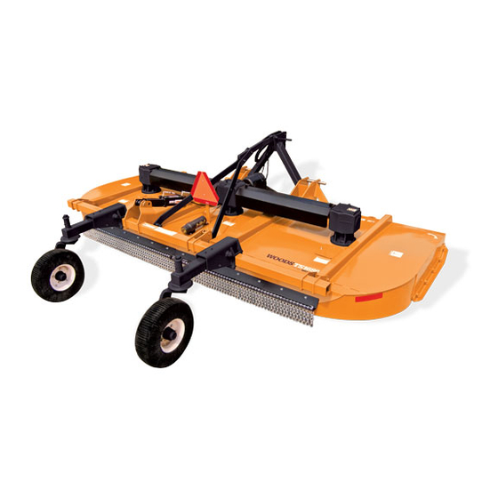
- Page 1 ROTARY CUTTER TS1680 TS1680Q...
-
Page 2: Introduction
Use only genuine Woods service parts. Substitute parts will void the warranty and may not meet standards required for safe and satisfactory operation. Record the model number and serial number of your equipment in the spaces... -
Page 3: Table Of Contents
TABLE OF CONTENTS INTRODUCTION ..........2 SPECIFICATIONS. -
Page 4: Specifications
SPECIFICATIONS TS1680 TS1680Q Cutting Height Range 2" to 13" 2" to 13" (varies with tire and wheel selection) Cutting Width 168" 168" Overall Width 176" 176" Overall Length (Pull-Type / Mounted) 158" / 123" 158" / 123" Tractor HP 50-200... -
Page 5: Safety Video Order Form
Safety Video Order Form BE SAFE! BE ALERT! BE ALIVE! BE TRAINED Before Operating Mowers! Safety Training Does Make a Difference. ASSOCIATION OF EQUIPMENT MANUFACTURERS Free Mower Safety Video Fill out and return the order form and we will send you a FREE VHS or DVD video outlining Industrial and Agricultural Mower Safety Practices . - Page 6 DVD Format - DVD01052 Safety Video Name: ________________________________________ Phone: __________________ Address: _____________________________________ _____________________________________ _____________________________________ Mower/Cutter Model: ______________________ Serial #: ________________________ Send to: ATTENTION: DEALER SERVICES WOODS EQUIPMENT COMPANY PO BOX 1000 OREGON IL 61061-1000 6 Safety Safety Video Order Form (Rev. 2/6/2006)
-
Page 7: Safety Rules
TACT A PHY SI CIAN IMM ED IAT ELY IF FLUID ENTERS SKIN OR EYES. DO NOT DELAY. Inspect chain shielding before each use. Replace if damaged. Never allow children or untrained persons to operate equipment. (Safety Rules continued on next page) Safety 7 TS1680 Safety Rules (6/29/2007) - Page 8 28-1/4" (718 mm) from attaching point center to center. Never direct discharge toward people, animals, or property. (Safety Rules continued on next page) (Rev. 8/30/2013) 8 Safety TS1680 Safety Rules (6/29/2007)
- Page 9 (Safety Rules continued on next page) (Rev. 8/30/2013) Safety 9 TS1680 Safety Rules (6/29/2007)
- Page 10 Disconnect hydraulic Disconnect cutter driveshaft and secure up off lines to optional cylinder. Disconnect driveline and ground. Raise cutter with 3-point hitch. Place secure up off the ground. 10 Safety TS1680 Safety Rules (6/29/2007)
-
Page 11: Safety Decals
Replacement safety decals can be ordered free from your Woods dealer. To locate your nearest dealer, check the Dealer Locator at www.WoodsEquipment.com, or in the United States and Canada call 1-800-319-6637. - Page 12 SAFETY & INSTRUCTIONAL DECALS ATTENTION! BECOME ALERT! YOUR SAFETY IS INVOLVED! Replace Immediately If Damaged! (Safety Decals continued from previous page) 8 - PN 18865 5 - PN 18864 WARNING DANGER FALLING OFF CAN RESULT IN BEING RUN OVER. ROTATING DRIVELINE ...
- Page 13 SAFETY & INSTRUCTIONAL DECALS ATTENTION! BECOME ALERT! YOUR SAFETY IS INVOLVED! Replace Immediately If Damaged! 10 - PN 1002940 AMBER FRONT REFLECTOR 9" 12 - PN 1004114 11 - PN 57123 RED REAR REFLECTOR 9" DANG NGER 19 - PN 20034034 RED / ORANGE FLUORESCENT 2" X 9" If shaft connection is visible, shield is missing.
-
Page 14: Operation
OPERATION port. A loose, dragging chain could be struck by The operator is responsible for the safe operation of the blades causing serious injury. the cutter. The operator must be properly trained. Operators should be familiar with the cutter, the tractor, and all safety practices before starting operation. -
Page 15: Hydraulic Connection
6. Remove parking jack from the tongue and attach it CONNECT CUTTER TO TRACTOR to the storage post on the front of the cutter. (MOUNTED) 7. Adjust H-frame bearing height so that the front Tractor Adjustments driveline is parallel to the ground. Secure with 1/2 x 5-3/4 clevis pin and 3/16 x 1 cotter pin. - Page 16 There must be at least 4 inches of overlap. If the driveline is too short (less than 4" overlap), contact your Woods dealer for a longer drive. Figure 5. Determine Shield Length 4. Cut the shield to the overall dimension (Figure 6).
-
Page 17: Cutting Height Adjustment
5. Place the cutoff portion of the shield against the 1. Cutter end of the shaft and use it as a guide. Mark and cut the shaft. See Figure 7. 2. Break link 3. Tractor top link 6. Repeat step 5 for other half of drive. 7. -
Page 18: Tractor Operation
ATTITUDE ADJUSTMENT (PULL-TYPE) TRACTOR OPERATION Use care when operating around tree limbs and other Normal Mowing low objects. For the most economical power use and best cutting Use care and reduce ground speed on rough terrain. results, the cutter should be from 1/2" to 3/4" higher at Always watch for hidden hazards. - Page 19 Cutter Operation imum transport speed. Doing so could result in: • Loss of control of the implement and tractor When beginning operation of the cutter, make sure that • Reduced or no ability to stop during braking all persons are in a safe location. Slowly move into the •...
- Page 20 PRE-OPERATION CHECK LIST ___ Check that all hardware is properly installed and secured. (OWNER'S RESPONSIBILITY) ___ Check to ensure blades are sharp, in good condi- ___ Review and follow all safety rules and safety tion, and installed correctly. Replace if damaged. decal instructions on pages 7 through 13.
-
Page 21: Owner Service
OWNER SERVICE The information in this section is written for operators The working surface must be level and solid to who possess basic mechanical skills. If you need help, support the weight on the jackstands. Make sure your dealer has trained service technicians available. jackstands are stable, both top and bottom. - Page 22 = Jackstand Placement DESCRIPTION FREQUENCY 1. Front U-Joint 10 hrs. 2. Mid U-Joint 10 hrs. 3. Carrier Bearing Block 40 hrs. 4. Telescoping Shaft 10 hrs. 5. Rear U-Joint 10 hrs. 6. Rotating Drive Shield 10 hrs. 7. Side Drive Yoke (2 Places) 40 hrs.
- Page 23 BLADE SERVICING NOTE: Always replace or sharpen both blades at the same time. Removing Blades (Figure 11) 1. Inspect blade bolt (1) and bushing (4) for nicks or gouges. Replace blade bolt if any defects are NOTICE found, Always replace lock nut (5) when changing ■...
-
Page 24: Slip Clutch Adjustment
1. Flange yoke 2. Friction disc 3. Hub, 1-3/4" 20-spline 4. Drive plate 5. Drive plate - SN 6. Thrust plate 7. 12 mm x 115 mm GR8.8 HHCS 8. Compression spring 9. Flat washer 10. 12 mm x 1.25P Nylok lock nut 11. - Page 25 1. Complete drive 2. Inner connector yoke 3. Outer connector yoke 1-3/4 20-spline 5. Rubber disk 6. Shaped washer 7. Bushing, .63 ID 8. Hex head cap screw 9. M16 x 2.0 Lock nut 10. Grease fitting 11. 3/8 NC x 3/4 Square head set screw Figure 14.
- Page 26 DECAL PN 1006348 ● Sand down scratches and the edges of areas of Figure 15. Split Rim Tire Servicing missing paint and coat with Woods spray paint of matching color (purchase from your Woods CLEANING dealer). After Each Use ●...
-
Page 27: Troubleshooting
TROUBLESHOOTING PROBLEM POSSIBLE CAUSE SOLUTION Does not cut Dull blades Sharpen blades. Worn or broken blades Replace blades. (Replace in pairs only.) Incorrect PTO speed Set at rated PTO speed. Ground speed too fast Reduce ground speed. Drive not functioning (blades do Check drive shaft connection. - Page 28 NOTES 28 Troubleshooting MAN0577 (6/29/2007)
-
Page 29: Dealer Service
DEALER SERVICE Seal Installation The information in this section is written for dealer service personnel. The repair described here requires NOTE: Proper seal installation is important. An special skills and tools. If your shop is not properly improperly installed seal will leak. equipped or your mechanics are not properly trained in this type of repair, you may be time and money ahead 1. - Page 30 8. Remove input bearing (2) by using a punch and Vertical seal should be recessed in housing. Horizontal seal (3) should be pressed flush with outside of hammer from outside of housing. housing. 9. Support housing in vise in a horizontal position. NOTE: Distortion to seal cage or damage to seal lip will 10.
- Page 31 Torque bolts to 300 lbs-ft. and 0.016". You should not have to adjust the 2. Attach crossbar (Crossbar Installation, page 35). backlash. 1a. Crown gear, 21T (TS1680) 1b. Crown gear, 22T (TS1680Q) 2. Input bearing 3. Oil seal (Horizontal shaft) 4.
- Page 32 M10 x 1.5P x 30 mm HHCS Cover Bearing, cup & cone Shim, 45.3 x 65.3 7a. Gear pinion (TS1680) 7b. Gear crown (TS1680Q) Castle nut, M36 x 3 Shim, 70.3 x 84.7 10. Shim, 50.3 x 70.3 11. Bearing, cup & cone 12.
- Page 33 Disassemble Gearbox 2. Wash housing and all components thoroughly. (Figure 15) Select a clean area for gearbox assembly. Replace 1. Remove dipstick plug from top of gearbox and all seals, bearings and gaskets. All parts must be siphon gear lube from housing. clean and lightly oiled before reassembly.
- Page 34 NOTE: Crossbar must be re-timed anytime a crossbar immerse the gearbox in water to verify that there are no leaks. or a side drive is disconnected. (See page 36.) 23. Remove gearbox from water and dry off with CROSSBAR compressed air. Add SAE 80W or 90W EP oil until level is between rings of dipstick (26) with dipstick Crossbar Removal seated.
- Page 35 Crossbar Installation 1. Using emery cloth (220 or finer), remove surface rust, and foreign material from hub, splined gearbox vertical shaft, and crossbar. See Figure Figure 19. Typical Crossbar and Gearbox Shaft 2. Install crossbar (2) on splined shaft. See Figure 20. Install nut (3).
- Page 36 Figure 21. Crossbar Timing - Bottom View Crossbar Timing Crossbar must be re-timed anytime a crossbar or a side drive is disconnected. 1. To re-time crossbars, position bars as shown in Figure 21. 2. The center crossbar will be at right angles to the front of the cutter.
- Page 37 U-Joint Assembly 1. Place seals securely on bearing cups. Insert cup into yoke from outside and press in with hand pressure as far as possible. Insert journal cross into bearing cup with grease fitting away from shaft. Be careful not to disturb needle bearings. Insert another bearing cup directly across from first cup and press in as far as possible with hand pressure.
-
Page 38: Assembly
DEALER SET-UP INSTRUCTIONS Install Attitude Rod Slide attitude rod (3) under right spindle driveline and These instructions are for the assembly of the TS1680 through pivot block on the tailwheel. Loosely install mounted and pull-type cutter. Many of the procedures sleeve (4), washer (22) and two hex nuts (23). - Page 39 27. 1/4 NC Nut 13. SMV Socket 14. SMV Bracket 28. Hub 15. SMV Emblem 29. 1/2 NF Lug nut 30. 1/ x 5 Headless pin Figure 28. TS1680 Pull-Type Cutter Assembly - Rear Half (Rev. 1/25/2008) Assembly 39 MAN0577 (6/26/2007)
- Page 40 TS1680 Pull-Type Assembly (Continued) 3. Attach rear tether chain on driveline to clip on plastic gearbox shield. FRONT HALF (Figure 29) H-Frame 1. Attach H-frame mounting bracket (2) to cutter deck Install Tongue with carriage bolts (34), washers (35) and lock nuts (30).
- Page 41 Figure 29. TS1680 Pull-Type Cutter Assembly - Front Half Assembly 41 MAN0577 (6/26/2007)
- Page 42 If using a cylinder other than the one supplied NOTE: Break links must rest on top of rear spacer by Woods, make sure a breather fitting is installed sleeve (9). in the cylinder rod end port. Use a restricter fitting in the base end port to dampen the cutter lowering action.
- Page 43 40. 1/4 NC x 1/2 Round head screw 14. 1/4 x 1/4 90° Elbow with 1/16 41. 1/4 NC Nut restricter 28. 1/2 NC x 3 HHCS 42. 1 x 5 Headless pin Figure 30. TS1680 Mounted Cutter Assembly (Rev. 1/25/2008) Assembly 43 MAN0577 (6/26/2007)
- Page 44 Center Gearbox carriage bolts (9) and lock nuts (10). 1. Make sure dipstick vent hole is clear. 9. 3/8 NC x 1-1/4 Carriage bolt 10. 3/8 NC Flange lock nut Figure 31. TS1680 Chain Shielding Installation 44 Assembly MAN0577 (6/29/2007)
- Page 45 1. Left light assembly (not shown) 2. Right light assembly (not shown) 3. Light bracket 4. Electronic module 5. 7" Tie strap 6. #10 x 1/2 Self-tapping screw 7. 1/4 NC x 1 HHCS GR5 8. 1/4 Lock nut 9. 3/8 NC x 4 HHCS GR5 10.
- Page 46 INSTALL SHREDDER KIT (OPTIONAL) 4. Attach two stationary blades (3) to blade holder using cap screws (7) and lock nuts (8). 1. Remove nut (9) and spacer (10) from blade pin 5. Attach plate (4) and two stationary blades (3) to link (11).
- Page 47 Figure 35. Stationary Blade Positions for 1000 RPM and 540 RPM Models Assembly 47 MAN0577 (6/26/2007)
-
Page 48: Dealer Check List
DEALER CHECK LISTS PRE-DELIVERY CHECK LIST DELIVERY CHECK LIST (DEALER’S RESPONSIBILITY) (DEALER’S RESPONSIBILITY) Inspect cutter thoroughly after assembly to make sure ___ Show customer how to make adjustments. it is set up properly before delivering it to the customer. Describe the options available for this cutter and The following check list is a reminder of points to explain their purpose. - Page 49 PARTS INDEX TS1680 Rotary Cutter MAIN FRAME ASSEMBLY........50 - 51 PULL-TYPE ASSEMBLY FRONT HALF .
- Page 50 MAIN FRAME ASSEMBLY 18 - Complete Decal Set 19 - English Safety Decal Set 43 - Spanish Safety Decal Set 50 Parts (Rev. 8/30/2013) MAN0577 (6/29/2007)
- Page 51 MAIN FRAME ASSEMBLY REF PART DESCRIPTION REF PART DESCRIPTION 1021420 Tailwheel weldment 18 1024798 Complete decal set Outer gearbox - 540 RPM (page 60) 1024795 19 1024799 English safety decal set -or- 39141 1 NC x 12 HHCS GR5 Outer gearbox - 1000 RPM (page 60) 1024797 34279 1 NC Lock nut...
- Page 52 PULL-TYPE ASSEMBLY - FRONT HALF 52 Parts MAN0577 (6/29/2007)
- Page 53 PULL-TYPE ASSEMBLY - FRONT HALF REF PART DESCRIPTION REF PART DESCRIPTION 1026245 Tongue Clevis pin, 1 x 2-1/2 1021377 CV H-frame mounting base 39070 Sleeve, 1.02 x 1.38 x .62 1021452 H-Frame 3489 1/2 NC x 3 HHCS GR5 23790 Parking jack 1/2 NC Lock nut 19407...
- Page 54 PULL-TYPE ASSEMBLY - REAR HALF REF PART DESCRIPTION REF PART DESCRIPTION Spring wheel arm (see page 72) ----- 8346 1 x 4-1/2 Headless pin 2 or 4 Tire & hub (see page 55) ----- 1285 1/4 x 1-1/2 Cotter pin 39385 Attitude rod 5/8 NC x 5 HHCS GR5...
- Page 55 WHEEL & TIRE ASSEMBLY PART DESCRIPTION PART DESCRIPTION 1017050 Heavy hub assembly 1017080F 22 x 6.6 x 10 Aircraft tire, rim & hardware, foam filled - 5 bolt -or- (includes items 1 through 15) 1017034 Heavy wheel hub with cups 1017030 29 x 9 x 15 Aircraft tire, (includes items 6, 7, 14)
- Page 56 MOUNTED CUTTER ASSEMBLY 56 Parts (Rev. 1/25/2008) MAN0577 (6/29/2007)
- Page 57 MOUNTED CUTTER ASSEMBLY REF PART DESCRIPTION REF PART DESCRIPTION Tailwheel (see page 70) ----- 6239 5/8 NC Lock nut 1021438 Rear A-frame link 34279 1 NC Lock nut 1021350 Front A-frame assembly 39141 1 NC x 12 HHCS GR5 39064 Lower hitch pin 19025 5/8 NC Flange lock nut...
- Page 58 CENTER GEARBOX ASSEMBLY 58 Parts MAN0577 (6/29/2007)
- Page 59 57471 Shim 45.3 x 65.3 (57471 kit) 22 1025608 Bearing, cup and cone 7a 1025615 2 or 1 Gear pinion 13T M9 (TS1680) -or- 23 1025616 Gear crown 24T M9 (TS1680) Gear crown 18T M8.6 (TS1680Q) 7b 1025609 24 1025610...
- Page 60 SIDE GEARBOX ASSEMBLY 60 Parts MAN0577 (6/29/2007)
- Page 61 1024797 Complete 1000 RPM Gearbox 57454 Output shaft assembly (TS1680Q) ----- B5 x 60 Cotter pin Gear crown 21T M7.8 (TS1680) 1a 1025617 57371 Oil cap 80 x 10 Gear crown 22T M7.8 (TS1680Q) 1b 1025611 17 1025614 Gear pinion 18T M7.9 (TS1680Q) 39411 Bearing, cup &...
- Page 62 TYPE A - 540 RPM FRONT CV DRIVE ASSEMBLY REF PART DESCRIPTION REF PART DESCRIPTION 1024175 Weasler 540 rpm front CV drive 1019641 Outer shield, CV complete 1021315 Inner shield, CV 19851 Slide lock repair kit, 1.38 ID 33347 Danger decal - shield missing (N/S) 58774 Yoke, QD CV 1.375-6 11 1021316...
- Page 63 TYPE B - 540 RPM FRONT CV DRIVE ASSEMBLY REF PART DESCRIPTION REF PART DESCRIPTION 1024175 Weasler 540 rpm front CV drive 1019641 Outer shield, CV complete 1021315 Inner shield, CV 19851 Slide lock repair kit, 1.38 ID 33347 Danger decal - shield missing (N/S) 1033103 Yoke, QD CV 1.375-6 11 1021316...
- Page 64 TYPE A - 1000 RPM FRONT CV DRIVE ASSEMBLY 1000 RPM 1-3/8 21-Splined 1000 RPM 1-3/4 20-Splined PART DESCRIPTION PART DESCRIPTION 1021102 Weasler 1000 RPM CV drive 1021101 Weasler 1000 RPM CV drive assembly complete, 21-spline assembly complete, 20-spline 19851 Slide lock repair kit, 1.38 ID 19837 Slide lock repair kit, 1.75 ID...
- Page 65 TYPE B - 1000 RPM FRONT CV DRIVE ASSEMBLY 1000 RPM 1-3/8 21-Splined 1000 RPM 1-3/4 20-Splined PART DESCRIPTION PART DESCRIPTION 1021102 Weasler 1000 RPM CV drive 1021101 Weasler 1000 RPM CV drive assembly complete, 21-spline assembly complete, 20-spline 19851 Slide lock repair kit, 1.38 ID 19837 Slide lock repair kit, 1.75 ID...
- Page 66 REAR FIXED-LENGTH DRIVE FOR CONSTANT VELOCITY DRIVE REF PART DESCRIPTION REF PART DESCRIPTION 1022223 Drive assembly complete 57432 Friction disc 1024779 Drive without shield 57442 Hub, 1-3/4 - 20 I.C. - SN 40566 Cross & bearing kit 57443 Drive plate 57421 Friction clutch 57256...
- Page 67 Complete 1000 RPM drive assembly - 40758 Slide lock collar repair kit (TS1680Q) -or- 40727 Outer guard half 40563 Yoke, 1-3/8 - 6-Spline ASG - (TS1680) 57273 Inner guard half -or- 40754 Male drive half, Complete (540 rpm) - 40757...
- Page 68 FLEXIBLE COUPLER PART DESCRIPTION 1021423 Complete drive ------- Inner connector yoke 1008147 Outer connector yoke 1-3/4 20-spline 1008140 Rubber disk 1008141 Shaped washer 1008142 Bushing, .63 I.D. 1001042 M16 x 2.0 x 90 mm HHCS 1008146 M16 x 2.0 Lock nut ------- * Grease fitting 90016031 *...
- Page 69 COUPLER SHAFT PART DESCRIPTION 1036890 Complete coupler shaft assembly 1040412 Yoke, QD 1-3/4-20 push pin 1040413 Cross & bearing assembly 1040414 Inner yoke & shaft 1040415 Outer yoke & tube 1040416 Yoke, QD 1-3/4-20 shear bolt 1040417 Push pin repair kit 1040418 Shear bolt repair kit Parts 69...
- Page 70 CASTER ARM ASSEMBLY - MOUNTED 70 Parts MAN0577 (6/29/2007)
- Page 71 CASTER ARM ASSEMBLY REF PART DESCRIPTION REF PART DESCRIPTION 39238 Caster yoke assembly 3689 1" Standard lock washer 4984 Heavy hub with long axle 3626 1-14 UNS Hex nut 7428 6.00 x 9 Solid tire & rim 21 OD 7431 Wheel, rim &...
- Page 72 SPRING WHEEL ARM ASSEMBLY - PULL TYPE REF PART DESCRIPTION 1021441 Spring arm 1021445 Lower spring arm 1021449 1.25 x 8.35 Pivot pin 17195 Compression spring 3.12 x .62 x 9.5 8424 3/4 x 2 x 3/8 Washer 52196 3/4 NC x 13 HHCS GR5 2371 3/4 NC Lock nut 10509...
- Page 73 CHAIN SHIELDING REF PART DESCRIPTION 1021456 Left front chain shield plate 1021457 Right front chain shield plate 1021458 Center front chain shield plate 1021461 Rear chain shield plate 5498 237 5/16 Chain, 6 link 1007850 Pin 31 to 33 chains 1007853 Pin 37 to 39 chains 1007856...
- Page 74 LIGHT KIT (OPTIONAL) PART DESCRIPTION 1022245 Complete TS1680 light kit 90401149 Light, 4 pin right 90401150 Light, 4 pin left 1022246 Light bracket 1004479 Wire harness 31407 7" Tie strap 21374 #10 x 1/2 Self-tapping screw 10378 1/4 NC x 1 HHCS GR5...
- Page 75 SHREDDER KIT (OPTIONAL) REF PART DESCRIPTION 1021463 Complete shredder kit 1021462 Blade holder 2 39004KT Double edge blade, .5 x 4 x 22.5 39089 Double edge blade, 3/8 x 4 x 11.13 39048 Link, .5 x 4 x 4 5607 * 5/8 NC x 1-1/2 Carriage bolt GR5 34473 * 5/8 NC x 3 HHCS GR5...
- Page 76 3-1/2 x 8" STROKE HYDRAULIC CYLINDER (OPTIONAL) REF PART DESCRIPTION REF PART DESCRIPTION 10475 Hydraulic cylinder complete, single 23543 Rod end housing, 1-1/4 bore acting (for pull-type & semi-mounted) 23546 Cylinder butt end -or- 923 * 1/4 x 1-3/4 Cotter pin 18725 Hydraulic cylinder complete, double 6698 *...
- Page 77 HYDRAULIC CYLINDER STROKE CONTROL KIT (OPTIONAL) REF PART DESCRIPTION 24098 Stroke control set for 1-1/4" cylin- der rod (contains items 2 - 5) – – – – 1-1/2" Segment – – – – 1-1/4" Segment – – – – 1" Segment –...
-
Page 78: Bolt Torque Chart
BOLT TORQUE CHART Always tighten hardware to these values unless a different torque value or tightening procedure is listed for a specific application. Fasteners must always be replaced with the same grade as specified in the manual parts list. Always use the proper tool for tightening hardware: SAE for SAE hardware and Metric for metric hardware. Make sure fastener threads are clean and you start thread engagement properly. -
Page 79: Bolt Size Chart
BOLT SIZE CHART NOTE: Chart shows bolt thread sizes and corresponding head (wrench) sizes for standard SAE and metric bolts. SAE Bolt Thread Sizes 5/16 Metric Bolt Thread Sizes 10MM 12MM 14MM 16MM 18MM ABBREVIATIONS AG .............. Agriculture MPa ............Mega Pascal ASABE ....American Society of Agricultural &... -
Page 80: Index
Category 2 Standard Hitch Category 3 Standard Hitch Dealer Set-Up Instructions Tractor Adjustments TS1680 Mounted Cutter Pull-Type TS1680 Pull-Type Cutter - Front Half Hydraulic Connection TS1680 Pull-Type Cutter - Rear Half Interference Check DEALER CHECK LISTS Turning Limits for Optional CV Driveline Cutting Height Adjustment Delivery (Dealer’s Responsibility) - Page 81 BW180XHD, BW1260X, BW1800X, BW240, BW240HD, DS1260, DSO1260, DS1440, TS1680 Under no circumstances will this Warranty apply in the event that the product, in the good faith opinion of WOODS, has been subjected to improper operation, improper maintenance, misuse, or an accident. This Warranty does not apply in the event that the product has been materially modified or repaired by someone other than WOODS, a WOODS authorized dealer or distributor, and/or a WOODS authorized service center.
- Page 82 Woods logo are trademarks of Woods Equipment Company. All other trademarks, trade names, or service marks not owned by Woods Equipment Company that appear in this manual are the property of their respective companies or mark holders. Specifications subject to change without notice.
Need help?
Do you have a question about the TS1680 and is the answer not in the manual?
Questions and answers