Table of Contents
Advertisement
Quick Links
Advertisement
Table of Contents

Related Manuals for Woods S105-3


Summary of Contents for Woods S105-3
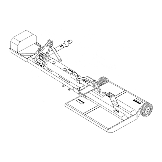
- Page 1 DITCH BANK ROTARY CUTTER S105-3 S106-3 S105Q-3 S106Q-3...
-
Page 2: Introduction
Operator’s Manual. If using the mail-in form, the dealer is to return the prepaid postage portion to Woods, give one copy to the customer, and retain one copy. Failure to register the product does not diminish customer’s warranty rights. -
Page 3: Table Of Contents
TABLE OF CONTENTS INTRODUCTION ..........2 SPECIFICATIONS. -
Page 4: Specifications
SPECIFICATIONS S105 S105Q S106 S106Q Cutting Width 60" 60" 72" 72" PTO Speed (rpm) 1000 1000 Blade Tip Speed (feet per minute) 11,451 14,137 10,178 12,566 Minimum Tractor Weight Recommended 4000 lbs 4000 lbs 5000 lbs 5000 lbs Minimum Tractor HP Recommended 40 HP 40 HP 50 HP... -
Page 5: Safety Video Order Form
Safety Video Order Form BE SAFE! BE ALERT! BE ALIVE! BE TRAINED Before Operating Mowers! Safety Training Does Make a Difference. ASSOCIATION OF EQUIPMENT MANUFACTURERS Free Mower Safety Video Fill out and return the order form and we will send you a FREE VHS or DVD video outlining Industrial and Agricultural Mower Safety Practices . - Page 6 DVD Format - DVD01052 Safety Video Name: ________________________________________ Phone: __________________ Address: _____________________________________ _____________________________________ _____________________________________ Mower/Cutter Model: ______________________ Serial #: ________________________ Send to: ATTENTION: DEALER SERVICES WOODS EQUIPMENT COMPANY PO BOX 1000 OREGON IL 61061-1000 6 Safety Safety Video Order Form (Rev. 2/6/2006)
-
Page 7: Safety Rules
SAFETY RULES ATTENTION! BECOME ALERT! YOUR SAFETY IS INVOLVED! Never allow children or untrained persons to Safety is a primary concern in the design and operate equipment. manufacture of our products. Unfortunately, our efforts to provide safe equipment can be wiped PREPARATION out by an operator’s single careless act. - Page 8 SAFETY RULES ATTENTION! BECOME ALERT! YOUR SAFETY IS INVOLVED! (Safety Rules continued from previous page) Do not operate or transport equipment while under the influence of alcohol or drugs. Power unit must be equipped with ROPS or ROPS cab and seat belt. Keep seat belt securely Use additional caution and reduce speed when fastened.
-
Page 9: Maintenance
SAFETY RULES ATTENTION! BECOME ALERT! YOUR SAFETY IS INVOLVED! Operate tractor PTO at 540 RPM (1000 RPM on Q ator's Manual instructions for working underneath Series cutters). Do not exceed. and blocking requirements or have work done by a qualified dealer. Raise or lower wings slowly to prevent personal injury or damage to cutter. -
Page 10: Safety Decals
ATTENTION! BECOME ALERT! YOUR SAFETY IS INVOLVED! Replace Immediately If Damaged! 11 - SERIAL NUMBER PLATE MODEL NO. SERIAL NO. Woods Equipment Company Oregon, Illinois, U.S.A. 1 - PN 32005 WARNING 2 - PN 25023 TO AVOID SERIOUS INJURY OR DEATH, DANGER Read Operator’s Manual and follow all safety, operating, and service... - Page 11 SAFETY & INSTRUCTIONAL DECALS ATTENTION! BECOME ALERT! YOUR SAFETY IS INVOLVED! Replace Immediately If Damaged! (Safety Decals continued from previous page) 4 - PN 29029 3 - PN 62211 -or- 3 - PN 23376 6 - PN 28527 DANGER 5 - PN 33347 DAN ER l l i .
- Page 12 Replacement safety decals can be ordered free from your Woods dealer. To locate your nearest dealer, check the Dealer Locator at www.WoodsEquipment.com, or in the United States and Canada call 1-800-319-6637.
-
Page 13: Operation 13
OPERATION The operator is responsible for the safe operation of Operate tractor PTO at 540 RPM (1000 RPM on Q the cutter. The operator must be properly trained. Series cutters). Do not exceed. Operators should be familiar with the cutter, the tractor, and all safety practices before starting operation. - Page 14 ATTACHING CUTTER TO TRACTOR height set and cutter level, set outer skid 1/2" above ground level and inner skid 1" above ground. The cutter is shipped with Category 2 hitch pins. Do not operate cutter with skids in constant contact Optional Category 1 pins may be substituted.
- Page 15 Always use the tractor hydraulic system with built-in ARNING float when available. On tractors with closed-center systems that do not have float, you may lock the con- trol in the down mode. This will allow the head to float. Do not disconnect hydraulic lines until machine is securely blocked or placed in lowest position Do not lock the control in the down mode on tractors and system pressure is released by operating...
- Page 16 Brush and Ditch Bank Mowing ARNING Never direct discharge toward people, animals, or property. ■ Do not raise cutter head with PTO engaged. A raised cutter head exposes blades and increases thrown object hazards. Always operate with cutter head close to surface being cut. When operating this cutter on ditch banks and cutting brush, the operator must be alert.
-
Page 17: Owner Service 17
OWNER SERVICE The information in this section is written for operators who possess basic mechanical skills. If you need help, your dealer has trained service technicians available. CAUTION For your protection, read and follow the safety informa- tion in this manual. Always wear relatively tight and belted clothing to avoid getting caught in moving parts. - Page 18 BLADE SERVICING Blade Installation NOTICE ® Apply liberal coating of Never Seez or equivalent to blade pin and crossbar hole. Make sure blade is offset ■ Do not handle blades with bare hands. Care- away from deck with cutting edge toward direction of less or improper handling may result in serious rotation.
-
Page 19: After Each Use
● Sand down scratches and the edges of areas of 6. Yoke & plate asy 14. Bolt missing paint and coat with Woods spray paint of 7. Bushing 15. Nut matching color (purchase from your Woods 8. Clutch hub w/bushing 16. -
Page 20: Troubleshooting
TROUBLE SHOOTING Problem Possible Cause Solution Does not cut Dull blades Sharpen blades. Worn or broken blades Replace blades. (Replace pairs only.) Incorrect PTO speed Be sure PTO speed is set at 540 or 1000 RPM. Make sure to check your unit’s rated PTO speed. -
Page 21: Gearbox Maintenance
DEALER SERVICE The information in this section is written for dealer ser- Leakage at the horizontal seal, top cover, or between vice personnel. The repair described herein requires the housing and side covers and side gear housings special skills and tools. If your shop is not properly can be corrected without removing gearbox from cutter. - Page 22 Removing Gearbox from Cutter (similar to adjusting front wheel bearings on an auto- mobile). Check by spinning housing. It should turn Remove safety shielding. Remove top cover and freely. siphon gear lube from gearbox. Remove drive lines. Remove crossbar (see Crossbar Removal). Remove If bearings are too tight, hold housing and rap gear gearbox from cutter.
- Page 23 1. Clevis 2. 5/8" x 4-1/2" Bolt 3. 5/8" Nut 4. Pad assembly 5. Tube assembly 6. Puller screw assembly 7. Crossbar puller link Figure 6. Crossbar Puller To remove crossbar with hydraulic jack, install the cle- vis (1) using the blade pin spacers, keyhole plates and bolts to each end of crossbar.
- Page 24 NOTICE ■ Incorrectly shimmed crossbars can cause costly damage to bearings and gearboxes. Follow these steps to obtain a properly shimmed crossbar. 1. 3/4 x 2-1/2 x 1/4 Flat washer 2. Shims Figure 10 NOTICE Figure 8 ■ 1. Using emery cloth (220 or finer), remove surface Failure to accomplish step three as outlined rust, Loctite and foreign material from gearbox will result in an improperly shimmed crossbar and...
-
Page 25: Universal Joint Repair
4. When you are certain you have correctly 6. When installing a clamp-type crossbar, install determined the proper shim pack, remove crossbar clamp bolts and torque to 85 lbs-ft. and apply blue Loctite retaining compound to Install crossbar block lock over bolt head. Place a vertical shaft. -
Page 26: U-Joint Assembly
2. With snap rings removed, support drive in vise, hold yoke in hand and tap on yoke to drive cup up out of yoke. See Figure 16. Figure 16 3. Clamp cup in vise as shown in Figure 17 and tap on yoke to completely remove cup from yoke. - Page 27 hammer. See Figure 19. Install snap ring and Operation repeat on opposite cup. The valve spool is equipped to operate a single-acting 4. Repeat step 1 & step 2 to install remaining cups in cylinder and has a float position detent. The spool will remaining yoke.
-
Page 28: Dealer Check Lists
DEALER CHECK LISTS PRE-DELIVERY CHECK LIST DELIVERY CHECK (DEALER’S RESPONSIBILITY) (DEALER’S RESPONSIBILITY) Inspect the equipment thoroughly after assembly to ___ Instruct customer how to lubricate and explain ensure it is set up properly before delivering it to the importance of lubrication. customer. -
Page 29: Dealer Set-Up Instructions
DEALER SET-UP INSTRUCTIONS Remove 1" Assembly of this cutter is the responsibility of the Woods dealer. It should be delivered to the owner com- pletely assembled, lubricated, and adjusted for normal cutting conditions. The cutter is shipped partially assembled. Assembly will be easier if aligned and loosely assembled before tightening hardware. -
Page 30: Lift Cylinder Installation
A-frame halves. Tighten all bolts securely. Torque hitch pin nuts to 300 lbs-ft and secure with cot- If a Woods valve is used, connect end of this hose to ter pins (56). quick coupler provided with valve. To other end of quick coupler, connect the 36"... -
Page 31: Blade Installation
Side Drive Installation (Figure 23) 1. Side drive mounting point 2. Drive joint support arm 3. Inner side drive assembly 4. Side drive mounting point 5. Outer side drive assembly 6. Drive joint support arm 10. 5/8 x 2-1/4" Bolt 11. - Page 32 Tire and Skid Assembly Installation Adjust so center frame and cutter frame ride with front slightly lower than rear for normal mowing. For varia- Refer to parts drawing on page 38. tions, see instructions in Operation section. The mower is shipped with skids assembled to rear Reinstall the shield on the cutter.
- Page 33 Tailwheel (Optional) Position valve on top of bracket as shown and secure with 3/8 x 2-1/2 bolts. Then position fender bracket on The tailwheel is ideal for mowing on relatively level right hand fender so controls are convenient to the ground, orchards, etc.
- Page 34 NOTES 34 Assembly 29977 (Rev. 1/23/2009)
-
Page 35: Parts Index
Rotary Cutters: S105-3, S106-3, S105Q-3 & S106Q-3 CENTER SECTION ASSEMBLY ......... . 36 CUTTER HEAD SECTION ASSEMBLY . - Page 36 CENTER SECTION ASSEMBLY 36 Parts 29977 (Rev. 1/23/2009)
-
Page 37: Hardware Description
CENTER SECTION ASSEMBLY PART DESCRIPTION PART DESCRIPTION 7112 Cat 2 hitch bushing adapter kit (bush- ----- Outer side drive assembly (pg 40) ings only for Cat 1 pins) -or- ----- Inner side drive assembly (pg 40) 13010 Cat 2 hitch mounting pin kit (mounting 9697 540 RPM Center frame (includes pins with 7/8 NF thread) -or-... - Page 38 CUTTER HEAD SECTION ASSEMBLY 38 Parts 29977 (Rev. 1/23/2009)
- Page 39 1014151 Right rear skid assembly (used on below, use #25774 bar & #11697 S105-3 and early S106-3) -or- chain) 22670 Rear skid assembly (used on S105-3 15831 Anti-wrap washer, 3.68 dia and early S106-3) HARDWARE 9695 S105-3 Frame (including gearbox, skids &...
- Page 40 TUBULAR SIDE DRIVE ASSEMBLY PART DESCRIPTION PART DESCRIPTION 23481 S105 Special yoke with bearing stub 13964 1-1/2 Square shaft 35R yoke 28" 35R, 10-11/16" long -or- 25766 Yoke, tube & bearing stub 23499 S106 Yoke, tube and bearing stub, 3886 * 1/4 x 1/4 x 1-1/4 Key 35R 16-11/16"...
- Page 41 CUTTER HEAD GEARBOX ASSEMBLY PART DESCRIPTION PART DESCRIPTION 11056 1-5/8 ID x 3 OD x 10 GA Flat washer 11155 S105 1.35:1 Gearbox complete -or- (used alone) -or- 11050 S106 1:1 Gearbox complete 25367 1-5/8 ID x 2-3/4 OD x 10 GA Flat 11007 1-5/8 Flanged nut washer (used with item 12)
- Page 42 INPUT GEARBOX ASSEMBLY PART DESCRIPTION PART DESCRIPTION 11555 Bearing cup, 3.81 OD 25731 540 RPM Gearbox 1:1 -or- 11556 Bearing cone, 2.25 ID 33315 1000 RPM Gearbox 1.5:1 17069 540 RPM 1:1 Horizontal gear and 4510 * 1/2 Pipe plug shaft -or- 1686 * 3/8 NC x 3/4 HHCS GR5...
-
Page 43: Standard Drive
FRONT HALF OF 2-JOINT DRIVE 35R STANDARD DRIVE 540 RPM 1000 RPM QTY DESCRIPTION 9476 33318 Tubular shaft & joint 35R, 11-1/2" 23495 23495 Tubular 11-1/2" shaft & yoke 35R Universal joint repair kit 35R 10938 Quick detach U-joint yoke 35R Lock pin &... -
Page 44: Slip Clutch Assembly
SLIP CLUTCH ASSEMBLY PART DESCRIPTION PART DESCRIPTION 12914 3/8 NC Wide flanged lock nut 25769 6S Clutch 1.5B 35R x 14-1/2" Square 13927 3/8 NC x 3-3/4 HHCS GR5 shaft 13921 * 7/16 NC Hex lock nut 23488 1-3/16 Square shaft with yoke 35R, 14-1/2"... - Page 45 INTEGRAL U-JOINT SHIELDING (USED ON EARLIER MACHINES) STANDARD DRIVE PART DESCRIPTION 24441 Integral U-joint shield kit, standard 7398 Integral shield snap ring 4677 Nylon rectangular groove bearing 35R 24443 U-Joint outer shield 10" 24442 U-Joint inner shield 9" LONG DRIVE REF PART DESCRIPTION 24444...
- Page 46 (15) and tie rods (6). Rotate rod end housing 180° so ports are on opposite sides. Reinstall tie rods and hex nuts. Torque to 55 lbs-ft. Woods purchases hydraulic cylinders from various manufac- REF PART DESCRIPTION turers. These cylinders have small dimensional differences.
- Page 47 Prince - Cylinder barrel (12) length is 10-1/2" long. Diameter REF PART DESCRIPTION of cylinder rod (19) is 1-1/4". ----- 3-1/2 OD Back-up washer ----- 3/16 x 3-1/2 OD O-ring REF PART DESCRIPTION ----- Rod end housing 23540 Seal kit (includes 2A - 2G) ----- Piston -----...
- Page 48 1 SPOOL, 3-WAY VALVE (OPTIONAL) PART DESCRIPTION PART DESCRIPTION 31077 Relief copper gasket 26995 1 Spool, 3-way valve w/open center, 31081 Relief valve adjustment shim complete 31090 Relief valve adjustment washer 31097 Lift check poppet 31076 Relief valve spring 31087 Check plug gasket 31096 Relief valve poppet follower...
- Page 49 PNEUMATIC TAILWHEEL ASSEMBLY PART DESCRIPTION PART DESCRIPTION 3097 5/8 NC x 4-1/2 HHCS GR5 13860 Pneumatic tailwheel asy complete 11872 3/4 x 11-1/16 Clevis pin 14125 Tailwheel yoke assembly 1285 * 1/4 x 1-1/2 Cotter pin 7276 7/16 x 2-1/2 Spirol pin 12443 Tailwheel attachment guide cup asy 19459...
- Page 50 PNEUMATIC TIRE ASSEMBLY FOR TAILWHEEL PART DESCRIPTION PART DESCRIPTION ----- 18 x 9.5 x 8 Inner tube ----- Rim for 18 x 9.5 x 8 tire 14255 18 x 9.5 x 8 Rib tire and 5-hole 1258 1/2 NF x 1-1/8 Wheel bolt wheel ----- 18 x 9.5 x 8 6-Ply rib tire...
-
Page 51: Tailwheel Assembly
TAILWHEEL ASSEMBLY PART DESCRIPTION PART DESCRIPTION 12577 4 x 8 Tire w/rim 5" wide 12907 1-1/2 Schedule 40 x 2-3/16 pipe 11131 Tailwheel yoke with 1" hole & offset (used on heavy yoke only) side arm (used with light #2302 hub 1257 * 3/4 Standard flat washer assembly only) - Page 52 TAILWHEEL & GAUGE WHEEL ASSEMBLY TAILWHEEL GAUGE PART PART DESCRIPTION 4676 ----- 4.00 x 8 Rim & laminated tire 4679 4679 4.00 x 8 Rim half ----- 25807 4.00 x 8 Rim & tire, 14" diameter 835 * 835 * 3/8 NC Hex nut, plated 838 * 838 *...
- Page 53 CROSSBAR PULLER ASSEMBLY PART DESCRIPTION PART DESCRIPTION 8811 Crossbar puller complete 24879 Crossbar puller pad assembly 19914 Crossbar puller clevis 24876 Crossbar puller tube assembly 3097 5/8 NC x 4-1/2 HHCS GR5 24881 Crossbar puller screw assembly 230 * 5/8 NC Hex nut 24885 Crossbar puller link Standard hardware, obtain locally...
-
Page 54: Bolt Torque Chart
BOLT TORQUE CHART Always tighten hardware to these values unless a different torque value or tightening procedure is listed for a specific application. Fasteners must always be replaced with the same grade as specified in the manual parts list. Always use the proper tool for tightening hardware: SAE for SAE hardware and Metric for metric hardware. Make sure fastener threads are clean and you start thread engagement properly. -
Page 55: Bolt Size Chart And Abbreviations
BOLT SIZE CHART NOTE: Chart shows bolt thread sizes and corresponding head (wrench) sizes for standard SAE and metric bolts. SAE Bolt Thread Sizes 5/16 Metric Bolt Thread Sizes 10MM 12MM 14MM 16MM 18MM ABBREVIATIONS AG .............. Agriculture MPa............Mega Pascal ASABE.... -
Page 56: Index
INDEX ASSEMBLY OPERATION Dealer Set-up Instructions 29 Attach Cutter to Tractor 14 Cutting Height & Attitude Adjustment 14 DEALER CHECK LISTS General Mowing 15 Delivery (Dealer’s Responsibility) 28 Blade Selection 15 Pre-Delivery (Dealer’s Responsibility) 28 Brush and Ditch Bank Mowing 16 DEALER SERVICE Cutter Head Lift 15 1-Spool, 3-Way Valve 27... -
Page 57: Product Warranty
BW1800, BW240, BW240HD, 2162, 3240, DS1260, DSO1260, DS1440, TS1680 Under no circumstances will this Warranty apply in the event that the product, in the good faith opinion of WOODS, has been subjected to improper operation, improper maintenance, misuse, or an accident. This Warranty does not apply in the event that the product has been materially modified or repaired by someone other than WOODS, a WOODS authorized dealer or distributor, and/or a WOODS authorized service center. - Page 58 ©1995 Woods Equipment Company. All rights reserved. WOODS, the Woods logo, and "Tested. Proven. Unbeatable." are trademarks of Woods Equipment Company. All other trademarks, trade names, or service marks not owned by Woods Equipment Company that appear in this manual are the property of their respective companies or mark holders.
Need help?
Do you have a question about the S105-3 and is the answer not in the manual?
Questions and answers