Table of Contents
Advertisement
Advertisement
Table of Contents

Summary of Contents for Bio-Tek ELx800
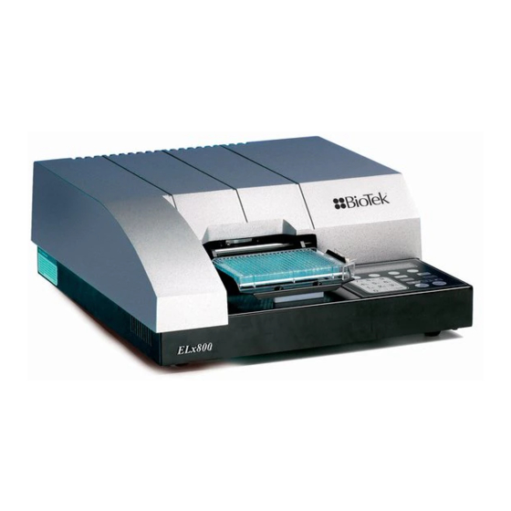
- Page 1 ELx800™ Absorbance Microplate Reader Operator’s Manual...
- Page 3 If a plate shaker is not available, wait 20 minutes after pipetting the diluted test solution before reading the plate. BIO-TEK INSTRUMENTS, INC., P.O. BOX 998, HIGHLAND PARK, WINOOSKI, VERMONT 05404 USA COPYRIGHT © 2005 TEL: (888) 451-5171 FAX: (802) 655-7941 Outside the USA: (802) 655-4740 E-mail: customercare@biotek.com www.biotek.com...
- Page 5 ELx800™ Absorbance Microplate Reader Operator’s Manual October 2004 2004 Part Number 7331000 Revision N Bio-Tek Instruments, Inc.
-
Page 6: All Rights Reserved
Bio-Tek Instruments, Inc. Changes made to the information in this document will be incorporated in new editions of the publication. No responsibility is assumed by Bio-Tek for the use or reliability of software or equipment that is not supplied by Bio-Tek or its affiliated dealers. -
Page 7: Table Of Contents
Directive 73/23/EEC Low Voltage ............xix Directive 2002/96/EC: Waste Electrical and Electronic Equipment ....xix Directive 98/79/EC: In Vitro Diagnostics ..........xix Electromagnetic Interference and Susceptibility........... xx User Safety .................... xx Safety Symbols..................xxi Warranty ..................... xxiii Registration Card .................. xxiv ELx800 Operator's Manual... - Page 8 | Preface Chapter 1: Introduction ..............1 Introducing the ELx800 Automated Microplate Reader ........2 Hardware Features ..................3 Software Features ..................3 Package Contents ..................4 Optional Accessories.................. 5 Specifications ................... 6 Standard Model ..................6 Ultraviolet/UV Model ................7 Narrow Beam/NB Model................
- Page 9 Contents | Repackaging and Shipping the ELx800 ............30 Before Repackaging the Instrument............30 Repackaging the ELx800 and Its Accessories ..........31 Preparing the Shipping Container ............37 Chapter 3: Operation ..............39 ELx800 Front Panel ................. 40 Overview ....................42 Recommendations for Achieving Optimum Performance ........
- Page 10 Chapter 5: Maintenance and Decontamination ......129 Maintenance..................130 Routine Cleaning Procedure ..............130 Purpose..................... 130 Tools and Supplies ................131 Procedure ..................131 Replacing the Bulb ................132 Decontamination Procedure ..............135 Tools and Supplies ................136 Procedure ..................136 Bio-Tek Instruments, Inc.
- Page 11 Controlling the Reader With KC4™............153 Problems ................... 154 Getting Started With KC4™ ..............154 Appendix B: Using 384-Well Geometry ......... 155 KCjunior™.................... 156 KC4™ ....................159 Appendix C: Report Format............163 Appendix D: Comparison of the ELx800 and the EL800....171 ELx800 Operator's Manual...
- Page 12 Sample Human Anticardiolipin IgG Enzyme Immunoassay Kit ...... 179 Intended Use ..................179 Background ..................179 Principle of the Assay ................179 Materials ................... 180 Quality Control and Results ..............181 Expected Values ................. 183 Programming the Human Anticardiolipin IgG Enzyme Immunoassay Kit ..184 Bio-Tek Instruments, Inc.
- Page 13 Figure 25: Protocol Definition (Read Method) Dialog ......158 Figure 26: KC4 Main Menu, System|Readers........159 Figure 27: Reader Selection Dialog............. 159 Figure 28: Data|New Plate Dialog............160 Figure 29: New Data File Dialog ............160 Figure 30: Reading Parameters Dialog ..........161 ELx800 Operator's Manual...
- Page 14 Figure 37: Assay Detail Report (Sheet 2 of 2) ......... 170 List of Tables Table 1: Recommended Test Schedule........... 105 Table 2: Typical Enzyme-Substrate Combinations and Stopping Solutions ... 116 Table 3: Test Tube Dilutions ..............121 Table 4: PBS 10X Concentrate Solution..........126 Bio-Tek Instruments, Inc.
-
Page 15: Contact Information
800-242-4685 (toll free in the U.S.) 802-655-4740 (outside the U.S.) Fax: 802-655-3399 E-Mail: tac@biotek.com European Coordination Center Bio-Tek Instruments GmbH Kocherwaldstrasse 34 D-74177 Bad Friedrichshall Germany Internet: www.biotek.de Phone: +49 (0) 7136 9680 Fax: +49 (0) 7136 968 111 E-Mail: info@biotek.de ELx800 Operator's Manual... -
Page 16: Document Conventions
Text in COURIER font represents menu options as they appear on DEFINE the instrument’s display. Note: Bold text is primarily used for emphasis. This icon calls attention to important information. Bio-Tek Instruments, Inc. -
Page 17: Revision History
Changed plate type information to include 384-well and 72-/96-well Terasaki plate formats. Added reference to Quick Read on display. 09/98 Modified Appendix B - Computer Control. Updated Elx800 and EL800 model comparison table in Appendix F. 2/99 Incorporated Manual Updates. - Page 18 Added new Appendix B, Using 384-Well Geometry. Updated sample reports in Appendix C, Report Format (formerly Appendix D). Removed previous Appendix A, Decontamination. Removed previous Appendix C, Error Codes. Added new Appendix E, Instructions for Programming a New Assay. Bio-Tek Instruments, Inc.
-
Page 19: Intended Use Statement
Failure to conduct Quality Control checks could result in erroneous test data. Repackaging and Shipping If you need to ship the instrument to Bio-Tek for service or repair, contact Bio-Tek for a Return Materials Authorization (RMA) number, and be sure to use the original packing. -
Page 20: Warnings
When operated in a safe environment according to the instructions in this document, there are no known hazards associated with the instrument. However, the operator should be aware of certain situations that could result in serious injury; these may vary depending on the instrument model. Bio-Tek Instruments, Inc. -
Page 21: Hazards And Precautions
For readers operated via computer control, no limits are applied to the raw absorbance data. All information exported via computer control must be thoroughly analyzed by the operator. ELx800 Operator's Manual... -
Page 22: Precautions
| Preface Precautions The following precautions are provided to help avoid damage to the instrument: Caution: Service. Only Bio-Tek authorized service personnel should service the instrument. Only qualified technical personnel should perform troubleshooting and service procedures on internal components. Caution: Environmental Conditions. -
Page 23: Directive 89/336/Eec:electromagnetic Compatibility
Traceability to the U.S. National Institute of Standards and Technology (NIST): Optical density measurements, and if equipped, incubator temperature readings, are traceable to NIST. Specific data for a particular serial number is available on request from Bio-Tek Instruments. See page xi for contact information. ELx800 Operator's Manual... -
Page 24: Electromagnetic Interference And Susceptibility
UL 61010A-1, 1st Edition • “Safety Requirements for Electrical Equipment for Measurement, Control, and Laboratory Use, Part 1: General Requirements” International EN 61010-1:2001 • “Safety Requirements for Electrical Equipment for Measurement, Control, and Laboratory Use, Part 1: General Requirements” Bio-Tek Instruments, Inc. -
Page 25: Safety Symbols
Borne de terre de protection Schutzleiteranschluss Borne de tierra de protección Terra di protezione On (Supply) Marche (alimentation) Ein (Verbindung mit dem Netz) Conectado Chiuso Off (Supply) Arrêt (alimentation) Aus (Trennung vom Netz) Desconectado Aperto (sconnessione dalla rete di alimentazione) ELx800 Operator's Manual... - Page 26 Separate collection for electrical and electronic equipment Les équipements électriques et électroniques font l’objet d’une collecte sélective Getrennte Sammlung von Elektro- und Elektronikgeräten Recogida selectiva de aparatos eléctricos y electrónicos Raccolta separata delle apparecchiature elettriche ed elettroniche Bio-Tek Instruments, Inc.
-
Page 27: Warranty
This Warranty is VOID if the Product has been repaired or altered by persons not authorized by Bio-Tek, or if the Product has had the serial number altered, effaced, or removed. This Warranty is VOID if the Product has not been connected, installed, or adjusted strictly in accordance with written directions furnished by Bio-Tek. -
Page 28: Registration Card
Once the instrument has been set up and is running successfully, please take a moment to fill out and mail the postage-paid Warranty Registration card. By sending in the registration card, you will be assured of receiving prompt information on product enhancements. Bio-Tek Instruments, Inc. -
Page 29: Chapter 1: Introduction
This chapter introduces the ELx800 Automated Microplate Reader and describes its hardware and software features. Also included is contact information if technical assistance is needed. Introducing the ELx800 Automated Microplate Reader ....2 Hardware Features..............3 Software Features..............3 Package Contents ..............4 Optional Accessories.............. -
Page 30: Introducing The Elx800 Automated Microplate Reader
The ELx800 is backed by a superior support staff. If the ELx800 ever fails to work perfectly, please call the Technical Assistance Center, or visit Bio-Tek’s Web site. -
Page 31: Hardware Features
Hardware Features | Hardware Features The ELx800’s hardware features include: • Single optics channel • Wavelength range of 400-750 nm ELx800UV model provides extended wavelength range of 340 to 750 nm • A 5-position filter wheel • A 2-line x 24-character LCD display •... -
Page 32: Package Contents
Chapter 1: Introduction Package Contents The contents of the ELx800 package include: • Microplate Reader • Power Cord (part number varies according to country of use) • Power Supply • Filter wheel with 4 standard filters: 405 nm, 450 nm, 490 nm, 630 nm and one blank filter. -
Page 33: Optional Accessories
• Lamp for ELx800NB, ELx800RNB, ELx800UV, ELx800RUV (PN 7330516) • Lamp for ELx800 and ELx800R (PN 7330513) • ELx800 filters (PN 7334---, plus wavelength) 340 (UV model only), 405, 415, 450, 490, 515, 540, 550, 562, 570, 590, 595, 600, 620, 630, 650, 660, 690, 750 •... -
Page 34: Specifications
Weight: 8 kg (18.5 lb. Maximum) • Environment: Operating temperature 18° to 40°C • Humidity: 10% to 85% noncondensing • Power Supply: Input 100 to 240 V~ ± 10.0% @ 50 to 60 Hz Output +24 VDC, 2.1 A Bio-Tek Instruments, Inc. -
Page 35: Ultraviolet/Uv Model
± 2.0% ± 0.020 OD from 0.000 to 2.000 OD @ 405 nm Linearity: ± 2.0% from 0.000 to 2.000 OD @ 405 nm Repeatability (STD): ± 1.0% ± 0.010 OD from 0.000 to 2.000 OD @ 405 nm ELx800 Operator's Manual... -
Page 36: Narrow Beam/Nb Model
@ 405 nm Linearity: ± 1.0% from 0.000 to 2.000 OD @ 405 nm ± 3.0% from 2.000 to 3.000 OD @ 450 nm Repeatability (STD): ± 0.5% ± 0.005 OD from 0 to 2.000 OD @ 405 nm Bio-Tek Instruments, Inc. - Page 37 ± 2.5% ± 0.020 OD from 0.000 to 2.000 OD @ 405 nm Linearity: ± 2.5% from 0.000 to 2.000 OD @ 405 nm Repeatability (STD): ± 2.0% ± 0.010 OD from 0.000 to 2.000 OD @ 405 nm ELx800 Operator's Manual...
-
Page 38: Technical Support
Your name and company information. • A fax number and/or e-mail address, if available. If you need to return the reader to Bio-Tek for service, contact Bio-Tek for a Return Materials Authorization number (RMA), repackage the reader properly (see Chapter 3... -
Page 39: Electronic Communication
Bio-Tek Instruments, Inc. Technical Assistance Center P.O. Box 998, Highland Park Winooski, Vermont 05404-0998 USA Shipping Address Ship instruments that need repair or service to Bio-Tek at the following address: Bio-Tek Instruments, Inc. Technical Assistance Center 100 Tigan Street Highland Park... - Page 40 Chapter 1: Introduction Bio-Tek Instruments, Inc.
-
Page 41: Chapter 2: Installation
Chapter 2 Installation This chapter includes instructions for unpacking and setting up the ELx800 and instructions for connecting printers and/or serial devices. Unpacking and Inspecting the ELx800™ ........14 Unpacking the Instrument and Its Accessories ......15 Setting Up the ELx800 ............. 19 Operating Environment ............ -
Page 42: Unpacking And Inspecting The Elx800
. If the original packing materials have been damaged, replacements are available from Bio-Tek. The ELx800 and its accessories are securely packaged inside custom-designed shipping materials. This packaging should protect the instrument from damage during shipping. Inspect the shipping box, packaging, instrument, and accessories for signs of damage. -
Page 43: Unpacking The Instrument And Its Accessories
Unpacking and Inspecting the ELx800™ | Unpacking the Instrument and Its Accessories Carefully open the top of the box, and remove the power supply shelf Figure 1 Remove the top foam end caps, manual, and Declaration of Conformity. Power supply... -
Page 44: Figure 2: Removing The Foam End Caps
). Place the reader on a level surface and remove the instrument from the plastic bag. Unpacking instructions Left end cap Unit inside 26 x 32 2-Mil poly bag Right end cap Figure 2: Removing the foam end caps Bio-Tek Instruments, Inc. -
Page 45: Figure 3: Removing The Top Cover Mounting Screws
Unpacking and Inspecting the ELx800™ | Carefully turn the ELx800 upside down on a level surface. Use the slotted screwdriver to remove the four screws from the top cover mounting ( Figure 3 ) and shipping straps from the bottom of the instrument. -
Page 46: Figure 4: Removing The Shipping Block
Figure 4 Shipping block Figure 4: Removing the shipping block Replace the top cover. Turn the instrument upside down and replace the mounting screws. Remove the shipping straps from the top of the carrier. Save these for repackaging/shipping. Bio-Tek Instruments, Inc. -
Page 47: Setting Up The Elx800
Setting Up the ELx800 Operating Environment The ELx800 is designed to operate optimally when installed on a level surface in an area where ambient temperatures remain between 18°C (64.4°F) and 40°C (104°F). The reader is sensitive to extreme environmental conditions, and these conditions should be avoided: •... -
Page 48: Power-Up And System Test
Chapter 2: Installation Power-Up and System Test After you have installed the ELx800 and connected the power supply, turn on the instrument to run a system test. The on/off switch is located on the lower right side of the base. -
Page 49: Configuring Global Default Options
Setting Up the ELx800 | Configuring Global Default Options The ELx800 contains several global configurable options, such as date and time, report output, and plate reading preferences. These options are accessed via the Select Utility Option menu ( Figure 5 below), and include: •... -
Page 50: Connecting A Printer To The Elx800
Place the printer in a location adjacent to the ELx800. Attach one end of the cable to the parallel port on the printer. Attach the other end of the cable to the parallel port on the ELx800. Tighten the securing screws on both ends of the cable. -
Page 51: Figure 6: Connectors For Printer (Parallel), Computer (Serial), And Power
Setting Up the ELx800 | Serial port Parallel port (printer port) Power supply jack Figure 6: Connectors for printer (parallel), computer (serial), and power supply ELx800 Operator’s Manual... -
Page 52: Setting Up The Serial Port For Communications With Other Devices
(such as a host PC running Bio-Tek’s KCjunior™ or KC4™ software), the communication parameters must match between the devices. The ELx800 has a 25-pin serial (RS-232) port located on the rear panel of the instrument. The serial port allows the reader to communicate with a computer, using standard communications software and/or RS-232 protocols. - Page 53 S T O P - B I T S D A T A - B I T S To change the baud rate (or other communications settings) in KC4™ or KCjunior™, refer to their respective user guides, or to Appendix A, Computer Control ELx800 Operator’s Manual...
-
Page 54: Installing Additional Filters
Installing Additional Filters Installed in the internal, five-position filter wheel are the filters that come standard with the ELx800 (standard models have 405, 450, 490, 630 nm filters; the UV model’s filter set is 405, 450, 490, 630 and 340 nm). - Page 55 Connect the power supply and cable to the rear of the instrument. Important! Store unused filters in a cool, dry place away from direct sunlight. The filters can be wrapped in a piece of lens paper to protect them from scratches and dust accumulation. ELx800 Operator’s Manual...
- Page 56 Chapter 2: Installation Checking the Reader’s Filter Table Setting After installing new filters, ensure that the ELx800’s filter table (the reader’s software reference for filter locations) matches the physical location of the filters. To check or change the software filter table: Power up the reader.
- Page 57 I N F O R M A T I O N : D A T E T I M E F I L T E R * M O R E Press the Main Menu key to return to the main menu. ELx800 Operator’s Manual...
-
Page 58: Repackaging And Shipping The Elx800
If you need to ship the ELx800 Reader to Bio-Tek for service or repair, be sure to use the original packing. Other forms of commercially available packing are not recommended and can void the warranty. -
Page 59: Repackaging The Elx800 And Its Accessories
Repackaging and Shipping the ELx800 | Repackaging the ELx800 and Its Accessories Refer to Figures 8 through when repackaging the ELx800. Move the carrier to the home position. Turn off the unit and unplug the power supply. Wrap the shipping straps around the carrier as shown in... -
Page 60: Figure 9: Hooking The Shipping Straps Around The Shaft
( Figure 9 Remove the four top cover mounting screws. Lift the instrument off the cover and turn it over. Shipping straps Mounting screws Post Top cover Figure 9: Hooking the shipping straps around the shaft Bio-Tek Instruments, Inc. -
Page 61: Figure 10: Installing The Shipping Block
Repackaging and Shipping the ELx800 | Install the shipping block. Place the groove in the shipping block over the shaft and screw it down ( Figure 10 Shipping block Shaft Figure 10: Installing the shipping block ELx800 Operator’s Manual... -
Page 62: Figure 11: Reinstalling The Top Cover
Chapter 2: Installation Turn the instrument over and install the top cover that was removed in step 6 ( Figure 11 Mounting screws Top cover Figure 11: Reinstalling the top cover Bio-Tek Instruments, Inc. -
Page 63: Figure 12: Reattaching The End Caps
Repackaging and Shipping the ELx800 | Turn the instrument right side up, and put the end caps on the unit Figure 12 Left end cap 26 x 32 2-Mil poly bag Right end cap Figure 12: Reattaching the end caps... -
Page 64: Figure 13: Placing The Unit In The Box
Place the shelf into the notched-out area in the end cap, and the power supply into an 8” x 11 ½” bubble bag. Place the power supply on the shelf. ( Figure 13 Shelf Power supply Figure 13: Placing the unit in the box Bio-Tek Instruments, Inc. -
Page 65: Preparing The Shipping Container
Make a note of any error messages displayed and their frequency. Provide Bio-Tek with the name and contact information of a person who may be contacted if questions arise. Close the box and tape it shut. - Page 66 Chapter 2: Installation Bio-Tek Instruments, Inc.
-
Page 67: Chapter 3: Operation
Chapter 3 Operation This chapter includes instructions for operating the ELx800 and its software. ELx800 Front Panel ..............40 Overview ................42 Recommendations for Achieving Optimum Performance....42 System Startup ..............43 Main Menu ................44 Define ................... 46 Define (Method, Map, Formula and Curve)........49 Defining METHOD ............... -
Page 68: Elx800 Front Panel
Chapter 3: Operation ELx800 Front Panel R E A D Y 9 : 4 5 A M 0 9 / 1 2 / 0 4 R E A D D E F I N E R E P O R T... - Page 69 ELx800 Front Panel | The keypad has four one below each selectable menu SOFT KEYS, option. Press a SOFT KEY to make a selection. For example, from the Main Menu, press the leftmost SOFT KEY to select READ, the rightmost to select UTIL.
-
Page 70: Overview
Do not turn on the instrument until the carrier shipping block has been removed. The ELx800 features a 25-pad keypad and a 2-line x 24-character LCD display, allowing you to access the reader’s program menus and print test results. The reader’s bidirectional serial port allows computer control of the instrument, and provides the means for downloading additional assay definition files to the instrument. -
Page 71: System Startup
System Startup | System Startup To turn on the ELx800, press the on/off switch on the right side of the reader’s base. The ELx800 will perform a System Test, displaying the screens shown below until initialization is complete. During this period, all keys are inactive. -
Page 72: Main Menu
Chapter 3: Operation Main Menu Following successful power-up of the ELx800, the Main Menu appears: R E A D Y 9 : 4 5 A M 0 1 / 3 1 / 0 3 R E A D D E F I N E... - Page 73 Single Wavelength 405 nm (editable) • 96-well plate geometry • Blank on Air • Automap • Map starting location A1 • Samples only (no blanks, standards or controls) • Sample count prompted at runtime (can be turned off in UTIL|READ options) ELx800 Operator’s Manual...
-
Page 74: Define
Specify a curve fit type and x/y axis types (lin/log). Specify whether or not standard outliers can be edited, and then the method by which they will be edited. Enable or disable the extrapolation feature (page 81). Bio-Tek Instruments, Inc. -
Page 75: Programming Note
C U R V E - F I T T Y P E : N O N E N O N E L I N E A R Q U A D * M O R E ELx800 Operator’s Manual... -
Page 76: Selecting An Assay To Define
The cursor is positioned at the first editable field, and advances automatically. The numeric range depends on the number of assays stored in the reader’s memory. The ELx800 has 55 “open” assays available; the EL800 has only 10. Press ENTER to advance to the EDIT ASSAY NAME screen. -
Page 77: Define (Method, Map, Formula And Curve)
The options appear on the display in the order that they were programmed in the assay. If the assay contains a closed variable (i.e., an element of the assay definition that you cannot access or modify), the entry screen is skipped. ELx800 Operator’s Manual... - Page 78 4 5 0 4 9 0 6 3 0 Select the wavelength. Use the right arrow key to move the cursor to REF and then select the Reference Filter. Press ENTER to move to the next screen. Bio-Tek Instruments, Inc.
- Page 79 Plate Type For 6- to 384-well standard plates, the plate types and sizes included in the software onboard the ELx800 are based on the brands listed below. For best measurement results, use these brands when operating the ELx800 via its onboard software.
- Page 80 6-well (2 x 3) 96-well (8 x 12) 12-well (3 x 4) 96-well Hellma Quartz (8 x 12) 96H: 24-well (4 x 6) 96-well Metric (8 x 12, 9 mm well 96M: 48-well (6 x 8) spacing) Bio-Tek Instruments, Inc.
-
Page 81: Defining Map
The 384-well plate type is preset for the map to have 384 samples. This does not include any blanking, controls, or standards. (Selecting 6-, 12-, 24-, 48-, or 96-well geometries enables data reduction capabilities.) ELx800 Operator’s Manual... - Page 82 Select MANUAL PLATE MAP GENERATION to indicate that the well assignments will be performed manually (by the user) at Define and/or Read time. • Press ENTER to save the selection and continue. Use the SHIFT-CLEAR keys to clear any previously defined manual map. Bio-Tek Instruments, Inc.
- Page 83 A1 and A2 wells. The third replicate would follow in B1. The next standard control, or sample, would follow in B2. • Press ENTER to save the selection and continue. Examples of mapping directions are shown on the next page. ELx800 Operator’s Manual...
- Page 84 STD3 STD4 STD4 STD5 STD5 Map Direction DOWN, Rep Direction ACROSS: STD1 STD1 STD2 STD2 STD3 STD3 STD4 STD4 STD5 STD5 Map Direction ACROSS, Rep Direction DOWN: STD1 STD2 STD3 STD4 STD5 STD1 STD2 STD3 STD4 STD5 Bio-Tek Instruments, Inc.
- Page 85 A01 to the last well on the plate, depending on the plate type and the number of blanks, standards, controls, and/or samples defined in the assay. • Press ENTER to save the well location and continue. ELx800 Operator’s Manual...
- Page 86 Select the BLANK MAP type (see the descriptions on the next page). • Press *MORE to cycle through the available options: ROW or COLUMN, and P-ACROSS or P-DOWN. • Press ENTER to save the well location and continue. Bio-Tek Instruments, Inc.
- Page 87 A, C, E and G rows. Manual mapping is recommended to set up the appropriate map by placing the standards, controls, and samples in only the A, C, E, and G rows. ELx800 Operator’s Manual...
- Page 88 B L A N K S : • Use the numeric keys to enter the number of blanks. The range is 0 to • Use the CLEAR key to clear the NUMBER OF BLANKS value from the display. • Press ENTER to continue. Bio-Tek Instruments, Inc.
- Page 89 12. The minimum is 4 for 4-P fit, cubic, cubic spline, and logit-log; 3 for quadratic; and 2 for linear and point-to-point. • Press CLEAR to clear the value on the display. • Press ENTER to continue. ELx800 Operator’s Manual...
- Page 90 Select YES to average the replicates for each standard group, and then use the group averages when calculating the standard curve. • Select NO to use the individual standard replicates when calculating the standard curve. • Press ENTER to continue. Bio-Tek Instruments, Inc.
- Page 91 The following table lists acceptable entries for well locations based on plate geometry: Plate Type Range 6-Well A01-B03 12-Well A01-C04 24-Well A01-D06 48-Well A01-F08 96-Well A01-H12 A01-H12 A01-H12 ELx800 Operator’s Manual...
- Page 92 Chapter 3: Operation Reuse of Standard Curves The ELx800 has the ability to reuse a standard curve that has already been established. Limitations of the Reuse of Standard Curves Standard curves can only be reused in assay positions 31 through 55.
- Page 93 For example, if the assay requires one or more positive control wells and one or more negative control wells, enter 02. • The valid entry range depends on the number of locations on the plate that are undefined. The maximum number of control groups is 8. ELx800 Operator’s Manual...
- Page 94 The valid entry range is from 1 to 12 replicates. The software automatically performs a check to ensure the number of replicates, multiplied by the number of controls, does not exceed the number of undefined wells remaining on the plate. Bio-Tek Instruments, Inc.
- Page 95 The range is 0 to the number of undefined well locations remaining on the plate. For example, if there are no controls, blanks, or standards defined on a 96-well plate, the maximum number of samples is 96, and the minimum number of samples is 1. ELx800 Operator’s Manual...
- Page 96 R E P # 1 : C 0 2 • Use the numeric alpha keys to enter the well location for Rep #1 of Sample Group #1. Press ENTER to advance to the next replicate or sample group. Bio-Tek Instruments, Inc.
-
Page 97: Defining Formula
KC4™. KCjunior and KC4 are PC-based software programs you can use to set up your assay, communicate with the ELx800 to run the assay, and then manipulate the raw data that is automatically retrieved from the reader. See Refer to for additional information. - Page 98 Chapter 3: Operation Formula Type The ELx800 supports three types of formulas, as well as the ability to define variables for use within Transformation formulas. Note: GENERAL formulas are not used. S E L E C T F O R M U L A...
- Page 99 Select FUNCTN to insert a mathematical function such as LOG or SQRT. The reader software checks the formulas for errors during data reduction. A syntax error in a formula will result in a “Token Error” on results reports. ELx800 Operator’s Manual...
- Page 100 Log10 2 = 0.301029995 ALOG10- Anti Log Base 10- LOG- Log- LOG 2 = 0.69314718 ALOG10 (0.30102995) = 2 AB- Absolute Value- AB (-1) = 1 SQRT- Square Root- SQRT 2 = 1.4142 PWR- Power- (10 PWR 2) = 100 Bio-Tek Instruments, Inc.
- Page 101 2.500, this can be accomplished with one formula: PC>1.000ANDPC<2.500 Or with two separate formulas: PC > 1.000 and PC < 2.500 Negative Control mean must have an OD of less than 0.100, the formula is: NC;x < 0.100 ELx800 Operator’s Manual...
- Page 102 If an assay protocol states that for the assay to be valid: The mean of the negative controls must be less than 0.100. The formula is: NC;x<0.100 The mean of the positive controls must be greater than the mean of the negative controls. The formula is: PC;x>NC;x Bio-Tek Instruments, Inc.
- Page 103 (OD), or just to the sample wells (SMP). S C O P E V A R I A B L E : S M P ELx800 Operator’s Manual...
- Page 104 - Subtract the mean of CTL1 from the mean of the NC. Subtract the difference from all ODs on the plate. - Divide the result of the above by the mean of the NC less the mean of CTL1, and then multiply by 100. Bio-Tek Instruments, Inc.
- Page 105 ENTER Enter STD1 as the TVAR formula. Press ENTER The formula selection screen is displayed. Choose TRANS. Enter the formula (OD/TVAR)*100 using the MATH, OTHER, MAP, and FUNCTION keys. “TVAR” is available as a MAP option. ELx800 Operator’s Manual...
- Page 106 The valid entry range is from 00 to 99%. An entry of 00% indicates no greyzone, although a sample equal to the cutoff value will still receive the EQUIV call. on the next page for information on Positive / Negative Calls how calls are assigned. Bio-Tek Instruments, Inc.
- Page 107 The greyzone is 00% • is selected for SAMP>CUTOFF+00% • Calls are assigned to sample wells as follows: EQUIV if the sample equals 1.500 POS if the sample is greater than 1.500 NEG if the sample is less than 1.500 ELx800 Operator’s Manual...
- Page 108 Calls are assigned to sample wells as follows: EQUIV if the sample is greater than or equal to 1.800 and less than or equal to 2.200 POS if the sample is greater than 2.200 NEG if the sample is less than 1.800 Bio-Tek Instruments, Inc.
-
Page 109: Defining Curve
• Extrapolation of Unknowns Note: These screens are displayed on the ELx800 in the order in which they appear in the assay. If a closed variable (i.e., an element of the assay definition that you cannot access or modify) is being used in the assay, the entry screen is omitted. - Page 110 Press SOFT KEYS 1, 2, 3, or 4 to select the curve-fit type that is displayed above the soft key. Select *MORE to display additional options. • Press ENTER to save the selection and advance to the next screen. Bio-Tek Instruments, Inc.
- Page 111 After the assay is run and reports are generated, press REPORT from the Main Menu. Press RESULT, select the assay, and then press ENTER . The EDIT STD OUTLIERS? YES/NO prompt will appear. on page 94 for further Editing Standard Outliers instructions. ELx800 Operator’s Manual...
- Page 112 “Ambiguous.” The resulting values, which actually are extrapolated, may not be indicated as such. All calculated results for an “Ambiguous” curve should be considered unreliable. Bio-Tek Instruments, Inc.
- Page 113 P A N E L S P A C E • The default name is “PANEL”. • Use the alpha numeric keys to update the assay name, if desired. • Press ENTER to continue. The NUMBER OF ASSAYS screen will appear. ELx800 Operator’s Manual...
- Page 114 Press Options to cycle through the assay numbers and names, or use numeric keys to enter an assay number. Press ENTER to make a selection. • After an assay is selected, its starting location must be defined. Bio-Tek Instruments, Inc.
- Page 115 The reader will print the map of each assay configured in the Panel. The Panel Assay results are sorted by sample (unless a custom assay has been programmed by Bio-Tek). Note: The interpretation of Results reports for each assay in the Panel will print first, and then the Sample results will print.
-
Page 116: Reading A Microplate
S P A C E E N T E R S A M P L E I D : 0 0 0 1 Place the plate in the carrier, and then press the READ key to continue. Bio-Tek Instruments, Inc. -
Page 117: Selecting An Assay To Run
, whether or not UTIL READ the assay specifies manual mapping, or if the assay was created or downloaded from Bio-Tek’s Extensions™ Define Reader Protocol software. • Prompts enabled via can include ENTER NUMBER OF UTIL READ SAMPLES, PLATE ID, and ENTER SAMPLE ID. - Page 118 Use caution when creating multiple Plate IDs. The reader does not warn you that you about to exceed the maximum of 8 plate IDs stored in memory. If a ninth Plate ID is added, it will overwrite the first Plate ID stored in memory. Bio-Tek Instruments, Inc.
- Page 119 • The sample well locations originally defined in the assay will be presented. If desired, use the keypad to enter new well locations for each sample replicate. • Press ENTER again to advance to the next replicate. ELx800 Operator’s Manual...
- Page 120 Place the plate in the carrier and press the READ key to initiate the plate read. • After the read is complete, data reduction will be performed (“Calculating Results…”), and then the reports will print (“Generating Reports…”). • To halt the read in progress, press the STOP key. Bio-Tek Instruments, Inc.
-
Page 121: Printing Reports
Select ASSAY to print a plate map and a listing of all of the assay’s settings, such as wavelengths, numbers of well types, formulas, and curve-fit parameters. • Select LIST to print a list of all assays (name and number) currently programmed in the ELx800. ELx800 Operator’s Manual... -
Page 122: Editing Standard Outliers
Select YES to indicate that one or more standard replicates or groups should be temporarily excluded from curve-fit calculations. If AVERAGE STANDARDS was set to NO in the assay definition, one or more standard replicates can be chosen for exclusion. Bio-Tek Instruments, Inc. - Page 123 4 for 2-P, 4-P, cubic, and cubic-spline; 3 for quadratic; and 2 for linear and point-to- point. Exercise caution when editing outliers. If the assay is left with insufficient standards, the curve fit will fail. ELx800 Operator’s Manual...
-
Page 124: Printing Results
List Report The List Report lists the all of the assays (name and number), currently programmed on the reader. • Select REPORT from the Main Menu, and then select LIST to print the report. Bio-Tek Instruments, Inc. -
Page 125: Using The Utility Options
To change the time format, select 12HOUR or 24HOUR, then AM or PM. The display automatically updates to reflect the new format. Press ENTER to return to the SELECT UTILITY OPTION menu. ELx800 Operator’s Manual... -
Page 126: Viewing/Editing The Filter Table
Chapter 3: Operation Viewing/Editing the Filter Table After installing new filters, ensure that the ELx800’s filter table (the reader’s software reference for filter locations) matches the physical location of the filters in the filter wheel. To edit the filter table: From the Main Menu, select UTIL SETUP. -
Page 127: Specifying Data Output And Reporting Options
E P S O N E P S O N The ELx800 supports printers using either HP's PCL3 language, such as the HP DeskJet series, or Epson's LQ language. For the latest list of compatible printers, consult the Bio-Tek Web site (www.biotek.com), or call Bio-Tek Instruments' Technical Assistance Center (refer to Chapter 1 for contact information). - Page 128 P R I N T C U R V E - F I T ? Y E S Select YES to print the standard curve (only applies to quantitative assays). Press ENTER to return to the SELECT UTILITY OPTION screen. Bio-Tek Instruments, Inc.
-
Page 129: Selecting Read Options
(single-wavelength assay). If NO is selected, the plate will be read in (approximately 50 seconds). Refer to Chapter 1 for NORMAL MODE specifications. Pressing ENTER after each selection advances the display. When selections are completed, the display returns to the SELECT UTILITY OPTION menu. ELx800 Operator’s Manual... - Page 130 Chapter 3: Operation Bio-Tek Instruments, Inc.
-
Page 131: Chapter 4: Performance Verification And Iq/Oq/Pq Procedures
Chapter 4 Performance Verification and IQ/OQ/PQ Procedures This chapter discusses the tasks and procedures necessary for verifying and qualifying instrument performance on an ongoing basis. A convenient Recommended Test Schedule arranges tasks into Installation, Operation, and Performance Qualification categories. Recommendations for Achieving Optimum Performance....104 Recommended Test Schedule ........... -
Page 132: Recommendations For Achieving Optimum Performance
Filter solutions to remove particulates that could cause erroneous readings. Although the ELx800™ supports standard flat, U-bottom, and V-bottom microplates, optimum performance is achieved with optically clear, flat- bottomed wells. -
Page 133: Recommended Test Schedule
Liquid Test 3, p. 125 Optional for 340 nm *Run Liquid Test 2 ONLY if you do not have an Absorbance Test Plate. If you run Liquid Test 2, you do have to also run Liquid Test 1. ELx800 Operator's Manual... -
Page 134: Qualification Procedures
Qualification Procedures You may use the tests outlined in this section to confirm initial and ongoing performance of the ELx800. Set up the ELx800 according to the instructions in Chapter 3, Installation . Confirm that the instrument powers up and communicates with peripherals for the Installation Qualification. -
Page 135: System Test
Refer to Chapter 2 The System Test is performed automatically whenever the instrument is turned on. It can also be performed manually through the ELx800 Main Menu. The reader will “chirp” repeatedly if the power-on System Test results do not meet the internally coded Failure Mode Effects Analysis (FMEA) criteria established by Bio-Tek. -
Page 136: Figure 16: Sample Output For The System Test (Sheet 1 Of 2)
Lambda: 999 Gain: 5.33 Resets: 1 Channel: Air: 19977 34186 Dark: 9900 10050 Delta: 10077 24136 Channel: Noise Max: 9878 9980 Noise Min: 9877 9978 Delta: Figure 16: Sample output for the System Test (sheet 1 of 2) Bio-Tek Instruments, Inc. -
Page 137: Checksum Test
7 3 3 0 2 9 1 - F W V 1 . 0 0 . 0 The second checksum test display will show the assay configuration software part number and version number. After a few moments, the Main Menu will reappear. ELx800 Operator's Manual... -
Page 138: Absorbance Plate Test
A reading of more than 0.015 OD for any of the designated alignment wells indicates that the light is being “clipped” and the ELx800 may be out of alignment. If the reader fails the alignment test, review the... - Page 139 Check the filters on the test plate to ensure that there is no debris that may have shifted between readings and caused changes. Check the microplate carrier to ensure that it is clear of debris. If these remedies are ineffective, call your Bio-Tek representative or Bio-Tek Technical Support. ELx800 Operator's Manual...
-
Page 140: Figure 18: Sample Absorbance Test Plate Data Sheet
Chapter 4: Performance Verification and IQ/OQ/PQ Procedures Requirements To run the Absorbance Plate Test, you need Bio-Tek's Absorbance 7-Filter Test Plate (Part Number 7260522), with its accompanying Data Sheet, shown in Figure 18 Figure 19 shows a sample Test Plate Analysis Report. -
Page 141: Entering The Absorbance Plate Specifications
Enter the values listed on the Test Plate Data Sheet. After each entry, press ENTER to advance to the next consecutive well location. Repeat for the remaining filters. When all values have been entered, press the Main Menu key. ELx800 Operator's Manual... - Page 142 When prompted, insert the Test Plate into the plate carrier, and press the READ key to begin the test. The Calibration Plate Analysis Report ( Figure 19 ) will be sent to a printer when the test is run. Bio-Tek Instruments, Inc.
-
Page 143: Test Failures
If any of the test parameters report as "FAIL," confirm that the standard values on the test plate data sheet match the values on the printout. If not, correct and retest. If the test still fails, contact Bio-Tek's Technical Assistance Center (refer to Chapter 1 for contact information). -
Page 144: Liquid Testing
“UV” model. It is offered for those sites that must have proof of linearity at wavelengths lower than those attainable with the Absorbance Test Plate. This test is optional since the ELx800™ has good “front end” linearity throughout the specified wavelength range (see page 125). -
Page 145: Stock Solution Formulation
Rinse the contents into a 1-liter volumetric flask. Add 0.5 ml of Tween 20, or 5 ml of Bio-Tek’s wetting agent. Make up to 1 liter with DI water, cap, and shake well. This should create a solution with an absorbance of about 2.000 when using 200 µl in a flat-bottom microwell. - Page 146 • 100-ml volumetric flask Preparation of Stock Solution: Pipette a 5-ml aliquot of Bio-Tek QC Check Solution No. 1 into a 100-ml volumetric flask. Make up to 100 ml with DI water; cap and shake well. This should create a solution with an absorbance of about 2.000 when using 200 µl in a flat-bottom microwell.
-
Page 147: Liquid Test 1
The well that shows the most variation for each concentration is selected for data reduction. For each mean below 2.000 OD, calculate the allowed deviation using the repeatability specification for a 96-well format of ± 0.5% ± 0.005 OD. ELx800 Operator's Manual... - Page 148 Repeatability Specification: For comparison in this test, the following repeatability specification is applied, using the Normal Read Mode and a 96-well microplate. ± 0.5% ± 0.005 OD from 0.000 to 2.000 OD @ 405 nm Bio-Tek Instruments, Inc.
-
Page 149: Liquid Test 2
1, 90% of the concentrated solution in tube 2, 80% in tube 3, and so on to 10% in tube 10. Dilute using amounts of the remaining 0.05% solution of deionized water and Tween 20, as shown in Table 3 ELx800 Operator's Manual... - Page 150 Range” and then click OK to perform the analysis. Note: If the Data Analysis command is not available on the Tools menu, you may need to install the Analysis ToolPak in Microsoft® Excel. Consult Excel’s help system for assistance. Bio-Tek Instruments, Inc.
- Page 151 Repeatability Specification: For comparison in this test, the following repeatability spec is applied, using Normal mode, 96-well microplate: ± 0.5% ± 0.005 OD from 0.000 to 2.000 OD @405 nm ELx800 Operator's Manual...
- Page 152 If the four corner wells are within the accuracy range, the reader is in alignment. Accuracy Specifications: For comparison in this test, the following accuracy specification is applied, using Normal Mode and a 96-well microplate: ± 1.0% ± 0.010 OD from 0.000 to 2.000 OD @ 405 nm Bio-Tek Instruments, Inc.
-
Page 153: Liquid Test 3 (For "Uv" Models Only)
Absorbance Test Plate. This test verifies operation of the ELx800™ at 340 nm and is optional because the reader has good “front-end” linearity throughout its wavelength range. -
Page 154: Table 4: Pbs 10X Concentrate Solution
1. Prepare a PBS solution using the Sigma powder. 2. In a beaker, mix 50 ml of the PBS solution (prepared from the Sigma powder) with 10 mg of the -NADH powder and mix thoroughly. This is the Sigma PBS Solution Bio-Tek Instruments, Inc. - Page 155 Print the five sets of raw data or export it to an Excel spreadsheet using KCjunior™ or KC4™. If you are exporting the data to an Excel spreadsheet, perform the calculations described on the following page, and keep the spreadsheet for future tests. ELx800 Operator's Manual...
- Page 156 Analysis ToolPak in Microsoft® Excel. Consult Excel’s help system for assistance. Expected Results: Since it is somewhat difficult to achieve high pipetting accuracy when conducting linear dilutions, an R-Square value greater than or equal to 0.990 is considered adequate. Bio-Tek Instruments, Inc.
-
Page 157: Chapter 5: Maintenance And Decontamination
Chapter 5 Maintenance and Decontamination This chapter contains procedures for maintaining and decontaminating the ELx800. Maintenance ................130 Routine Cleaning Procedure............130 Replacing the Bulb ..............132 Decontamination Procedure............135... -
Page 158: Maintenance
Do not immerse the instrument, spray it with liquid, or use a “wet” cloth. Do not allow the cleaning solution to run into the interior of the instrument. If this happens, contact the Bio-Tek Service Department. Do not soak the keypad—this will cause damage. Moisten a clean cloth with deionized or distilled water and wipe the keypad. -
Page 159: Tools And Supplies
Do not soak the cloth. Wipe the plate carrier and all exposed surfaces of the instrument. If detergent was used, wipe all surfaces with a cloth moistened with water. Use a clean, dry cloth to dry all wet surfaces. ELx800 Operator's Manual... -
Page 160: Replacing The Bulb
*MORE until BULB ALIGN is displayed. The carrier will move to the bulb alignment position. E D I T S E T U P B U L B A L I G N * M O R E Bio-Tek Instruments, Inc. -
Page 161: Figure 20: Lamp Assembly
Replacing the Bulb | Bulb assembly Bulb retainer Optics arm Filter wheel cover Lamp retention screws Lead wires Optics arm cover Optics arm #1 aperture Lamp retention screws Figure 20: Lamp assembly ELx800 Operator's Manual... - Page 162 Tighten the lamp retention screws and verify that the lamp has not moved. After completing the alignment, turn the instrument off and on again to return the carrier to the home position. Bio-Tek Instruments, Inc.
-
Page 163: Decontamination Procedure
Centers for Disease Control and Prevention (CDC). Neither Bio-Tek nor the CDC assumes any liability for the adequacy of these solutions and methods. Each laboratory must ensure that decontamination procedures are adequate for the Biohazard(s) they handle. -
Page 164: Tools And Supplies
“wet” cloth. Do not allow the cleaning solution to run into the interior of the instrument. If this happens, contact the Bio-Tek Service Department. Do not soak the keypad—this will cause damage. Important! Turn off and unplug the instrument for all decontamination and cleaning operations. - Page 165 7. Use a clean, dry cloth to dry all wet surfaces. 8. Discard the used gloves and cloths using a Biohazard trash bag and an approved Biohazard container. ELx800 Operator's Manual...
- Page 166 Chapter 5: Maintenance and Decontamination Bio-Tek Instruments, Inc.
-
Page 167: Chapter 6: Troubleshooting And Error Codes
Chapter 6 Troubleshooting and Error Codes This appendix describes potential error codes that may be displayed on the ELx800, and suggests possible solutions for these problems. Overview ................140 System Test Description ............140 Glossary of Terms ...............140 Error Codes ................141 General Errors ..............142... -
Page 168: Overview
If an error is displayed, consult the error code list to see if the error is easily correctable. If you cannot resolve the problem, run the instrument System Test and note the exact error code and serial number of the reader. Then call Bio-Tek’s Technical Assistance Center (refer to Chapter 1 for contact information). -
Page 169: Error Codes
“A” indicates a more serious error. In this case, turn off the instrument. Upon restarting the instrument, you should be able to use the keypad. See Fatal Errors on page 148 for more information. Contact Bio-Tek's Technical Assistance Center for further assistance if any of error codes are displayed. Refer to Chapter 1 for contact information. -
Page 170: General Errors
Flex cable is disconnected or damaged. • X-axis movement is limited so that the optical sensor cannot be interrupted. Note: In cases where a sensor is not functioning, the motor will drive the axis to its mechanical stop and generate substantial noise. Bio-Tek Instruments, Inc. - Page 171 • Failed lamp. • Loose filter wheel drive gear or defective motor controller PCB. 0302 Filter wheel failed positional verify; lamp failed • A failed lamp generates a 0302 error on power-up. ELx800 Operator's Manual...
- Page 172 Bearings caused motors to fail. 0500 Filter not installed Probable Causes: • Empty filter location on the filter wheel (all filter locations must have either a filter or a filter blank, Bio-Tek PN 2872086). • Entire filter wheel is not installed. Bio-Tek Instruments, Inc.
- Page 173 There may be an ambient light leak. Ensure that the plate carrier door is properly closed. Faulty motherboard (PN 7330400, 7330410, or 7330415) or daughter board (PN 7330404, or 7330414). Photodiode or power supply may be too close to the instrument. ELx800 Operator's Manual...
- Page 174 Printer timed out The time allotted for the instrument to make a valid connection to a printer has expired. Probable Causes: Printer not connected, on line, or powered up. • Printer parallel port may not be correctly selected. • Bio-Tek Instruments, Inc.
- Page 175 Error Codes | General Errors (Continued) Errors 0D00 through 1300 indicate that the reader has failed one or more of a number of self-tests. Contact Bio-Tek’s Technical Assistance Center for instructions. Refer to Chapter 1 for contact information. 0D00 Calibration checksum error Reader failed calibration checksum test.
-
Page 176: Fatal Errors
• these errors on pages 142 and 143. Fatal Errors Fatal Errors indicate conditions that require immediate attention. If a fatal error is displayed, contact Bio-Tek’s Technical Assistance Center for further instructions. Refer to Chapter 1 for contact information. Code... -
Page 177: Appendix A: Controlling The Reader With Kcjunior™ Or Kc4
Appendix A Controlling the Reader With KCjunior™ or KC4™ The ELx800 can be controlled either from Bio-Tek’s KCjunior™ or KC4™ PC Software. This Appendix provides instructions for programming the computer to control the reader. Overview ................150 Controlling the Reader With KCjunior™ ........151 Problems................ -
Page 178: Overview
Using KCjunior™ or KC4™ software provides the user even more power and flexibility. For example, complex assays using features not available through the front panel may be defined and run. This Appendix provides instructions for controlling the reader with Bio-Tek’s KCjunior™ or KC4™ software packages. Bio-Tek Instruments, Inc. -
Page 179: Controlling The Reader With Kcjunior
Controlling the Reader With KCjunior™ Controlling the Reader With KCjunior™ The ELx800 can be operated using a computer running Bio-Tek's KCjunior software. Follow the steps below: Power off the computer and the reader. Connect the serial cable (PN 75053) between the two machines. -
Page 180: Problems
The plate will be read and then the raw data results will display in KCjunior. Print the raw data by selecting Plate|Print Results. To analyze or manipulate results, a protocol should be defined. Refer to KCjunior's Help system or User's Guide for instructions. Bio-Tek Instruments, Inc. -
Page 181: Controlling The Reader With Kc4
Controlling the Reader With KC4™ Controlling the Reader With KC4™ The ELx800 can be operated using a computer running Bio-Tek's KC4 software. Follow the steps below: Power off the computer and the reader. Connect the appropriate serial cable (PN 75053) between the two machines. -
Page 182: Problems
The plate will be read and then the raw data results will display in KC4. To analyze, manipulate, or print results, parameters protocol should be defined. Refer to KC4's Help system or User's Guide for instructions. Bio-Tek Instruments, Inc. -
Page 183: Appendix B: Using 384-Well Geometry
Appendix B Using 384-Well Geometry The following describes how to manipulate data received from a plate with 384-well geometry. To capture and manipulate the raw data using 384-well geometry, you must use KCjunior or KC4 . The Optical Density values will be ™... -
Page 184: Kcjunior
Appendix B: Using 384-Well Geometry KCjunior™ KCjunior, Bio-Tek’s data reduction package for Windows , can control the ELx800 ® in 6-, 12-, 24-, 48-, 96-, and 384-well formats, as well as in 60-, 72- ,and 96-well Terasaki plate formats. Start KCjunior. -
Page 185: Figure 23: Read Plate Dialog
KCjunior™ | Click to enter the Read Plate Results ID Plate Description Figure 23: Read Plate dialog Choose New Protocol to define the protocol. Figure 24: Protocol Definition (General Information) dialog ELx800 Operator’s Manual... -
Page 186: Figure 25: Protocol Definition (Read Method) Dialog
Appendix B: Using 384-Well Geometry Define the parameters. Read Method Set the Plate Geometry 8 x 12 Figure 25: Protocol Definition (Read Method) dialog Click to read the plate and display the results. Bio-Tek Instruments, Inc. -
Page 187: Kc4
KC4™ | KC4™ Bio-Tek’s KC4 data reduction package can control the ELx800 in 6-, 12-, 24-, 48-, 96, and 384-well formats, as well as in 60-, 72-, and 96-well Terasaki plate formats. Start KC4. At KC4’s main menu, choose System|Readers... -
Page 188: Figure 28: Data|New Plate Dialog
Figure 28: Data|New Plate dialog If prompted to select a protocol, select “Empty Protocol” and click If not prompted, select Protocol|New , or use KC4’s Protocol Wizard to step through protocol creation. Figure 29: New Data File dialog Bio-Tek Instruments, Inc. -
Page 189: Figure 30: Reading Parameters Dialog
The plate will be read and then the raw data results will display in KC4. To analyze, manipulate, or print results, protocol parameters should be defined. Refer to KC4's Help system or User's Guide for instructions. ELx800 Operator’s Manual... - Page 190 Appendix B: Using 384-Well Geometry Bio-Tek Instruments, Inc.
-
Page 191: Appendix C: Report Format
Appendix C Report Format This appendix contains examples of reports that can be generated and/or printed from the ELx800. Refer to Printing for details on how to print these Reports Chapter 3 reports. In addition, an Assay List, Assay Definition, Map, and Result can be printed by choosing Report from the Main Menu screen. -
Page 192: Figure 31: Samples With Calls On Matrix Report
Appendix C: Report Format Figure 31: Samples with calls on Matrix Report Bio-Tek Instruments, Inc. -
Page 193: Figure 32: Curve Fit Report
Figure 32: Curve Fit Report ELx800 Operator's Manual... -
Page 194: Figure 33: Samples With Calls On Column Report
Appendix C: Report Format Figure 33: Samples with calls on Column Report Bio-Tek Instruments, Inc. -
Page 195: Figure 34: Column Report Without Samples
Figure 34: Column Report without samples ELx800 Operator's Manual... -
Page 196: Figure 35: Panel Report
Appendix C: Report Format Figure 35: Panel Report Bio-Tek Instruments, Inc. -
Page 197: Figure 36: Assay Detail Report (Sheet 1 Of 2)
Figure 36: Assay Detail Report (Sheet 1 of 2) ELx800 Operator's Manual... -
Page 198: Figure 37: Assay Detail Report (Sheet 2 Of 2)
A S S A Y A S S A Y A S S A Y A S S A Y A S S A Y A S S A Y Figure 37: Assay Detail Report (Sheet 2 of 2) Bio-Tek Instruments, Inc. -
Page 199: Appendix D: Comparison Of The Elx800 And The El800
Appendix D Comparison of the ELx800 and the EL800 The following chart compares the features on the ELx800 and EL800 microplate readers. Feature ELx800 EL800 340-750 nm 405-750 nm Single- and dual-wavelength reading 6-well plates 12-well plates 24-well plates 48-well plates... - Page 200 Appendix D: Comparison of the ELx800 and the EL800 Bio-Tek Instruments, Inc.
-
Page 201: Appendix E: Instructions For Programming A New Assay
The kit instructions are provided so that users can see how it is possible to translate the kit wording into an ELx800 assay program. For clarity, only the user menu choices from the reader screens are shown. -
Page 202: Sample Ana Screen Enzyme Immunoassay Kit
Phosphoric acid is added to each well to stop the reaction. This produces a yellow end-point color, which is read at 450 nm. Bio-Tek Instruments, Inc. -
Page 203: Materials
This should be of the highest • quality available. Calibrated Micropipettes: For dispensing 1000, 100, and 10 µl. • Multichannel Pipette: Recommended for dispensing 100 µl • volumes of conjugate, substrate, and stop solution. • Glass/Plastic Tubes: For sample dilution. ELx800 Operator's Manual... -
Page 204: Quality Control And Results
It is recommended that each laboratory determine its own normal range, based on the population techniques and equipment employed. ANA Result Interpretation < 10.0 Negative > 10.0 Positive Bio-Tek Instruments, Inc. -
Page 205: Programming The Ana Screen Enzyme Immunoassay Kit
Choose to blank on “AIR” if no blank wells are required NUMBER STDS: 00 NUMBER CTLS: 03 CONTROL 1: PC CONTROL 2: CTL1 Suggested choice for the cutoff control CONTROL 3: NC NUMBER OF REPLICATES PC: 01 CTL1: 03 ELx800 Operator's Manual... - Page 206 TRANS: FORMULA: (OD/TVAR)*10 Converts all OD values on plate to ”ANA Result” per kit insert instructions To define a cutoff formula for Positive and Negative calls: FORMULA CUTOFF: 10.0 GREYZONE: 00% SAMPLE > CUTOFF + 00%: POS Bio-Tek Instruments, Inc.
-
Page 207: Sample Human Anticardiolipin Igg Enzyme Immunoassay Kit
Phosphoric acid is added to each well to stop the reaction. This produces a yellow end-point color, which is read at 450 nm. ELx800 Operator's Manual... -
Page 208: Materials
Cardiolipin IgG Conjugate: peroxidase labeled antibody. Colored red, ready to use. • TMB Substrate: 1 bottle containing 14 ml TMB substrate. Ready to use. • Stop Solution: 1 bottle containing 14 ml of 3M phosphoric acid. Ready to use. Bio-Tek Instruments, Inc. -
Page 209: Quality Control And Results
Calculate Mean Optical Densities (for assays run in duplicate only) For each standard, control and sample calculate the mean OD of the duplicate readings. The user must verify that the percentage coefficient of variation (%CV) for each duplicate OD is less than 15.0%. ELx800 Operator's Manual... - Page 210 The Louisville reference center recommends the following positive discrimination criteria according to the recommendation of the 2 International Anticardiolipin Workshop. Criteria Range (GPLU/ml) High Positive > 80 Medium Positive ≥ 20-80 Low Positive ≥ 10, < 20 Bio-Tek Instruments, Inc.
-
Page 211: Expected Values
It is recommended that each laboratory determine its own normal range, based on the population techniques and equipment employed. IgG Anticardiolipin < 11 GPL U/ml Negative result > 11 GPL U/ml Positive result ELx800 Operator's Manual... -
Page 212: Programming The Human Anticardiolipin Igg Enzyme Immunoassay Kit
NUMBER STDS: 05 NUMBER STD REPLICATES: 01 CONCENTRATIONS: STD1: 6.25 STD2: 12.5 STD3: 25 STD4: 50 STD5: 100 NUMBER CTLS: 02 CONTROL 1: PC CONTROL 2: NC NUMBER OF REPLICATES PC: 01 NC: 01 SAMPLES: 89 SAMPLE REPLICATES: 01 Bio-Tek Instruments, Inc. - Page 213 Kit instructions specify that samples Negative calls: with concentration values greater than 11 should appear as positive. The ELx800 software calculates the cutoff based on absorbance value or transformed value (see the previous example) and cannot calculate based on concentration. The technician must...
- Page 214 Appendix E: Instructions for Programming a New Assay Bio-Tek Instruments, Inc.
Need help?
Do you have a question about the ELx800 and is the answer not in the manual?
Questions and answers