Table of Contents
Advertisement
Quick Links
Advertisement
Chapters
Table of Contents
Troubleshooting

Subscribe to Our Youtube Channel
Related Manuals for Jacobsen SXG323


Summary of Contents for Jacobsen SXG323
- Page 1 LAWN MOWERS: MOWER DECKS: SCMB48 & SCMA54 COLLECTORS: SBC550X & 600X...
-
Page 2: Foreword
ISEKI LAWN MOWERS FOREWORD This service manual has been prepared to provide the information and suggestions necessary for servicing the ISEKI SXG Lawn Mower. These include construction, specifications, removal and reinstallation of the components, disassembly and reassembly instructions, inspection and adjustment instructions, troubleshooting, general precautions etc. -
Page 3: Table Of Contents
SERVICE MANUAL FOR SXG323&326 TOTAL CONTENTS LAWN MOWERS CHAPTER 1. GENERAL INFORMATION ..................11 CHAPTER 2. DISASSEMBLY OF MAJOR COMPONENTS ............17 CHAPTER 3. ENGINE ACCESSORIES ..................27 CHAPTER 4. ENGINE ........................33 CHAPTER 5. LUBRICATION SYSTEM ..................67 CHAPTER 6. COOLING SYSTEM ....................73 CHAPTER 7. - Page 4 CHAPTER 1 CHAPTER 2 CHAPTER 3 CHAPTER 4 CHAPTER 5 CHAPTER 6 CHAPTER 7 CHAPTER 8 CHAPTER 9 CHAPTER 10 ISEKI LAWN MOWERS ISEKI LAWN MOWERS CHAPTER 11 SXG323 & 326 SXG323 & 326 CHAPTER 12 CHAPTER 13...
- Page 6 ISEKI LAWN MOWERS TABLE OF CONTENTS FOREWORD ............................. 1 TOTAL CONTENTS .......................... 2 TABLE OF CONTENTS ........................5 CHAPTER 1. GENERAL INFORMATION ..................11 1. MODEL NAME AND IDENTIFICATIONS NUMBERS .............. 11 2. SPECIFICATIONS ........................12 3. EXTERIOR VIEW ........................13 4.
- Page 7 SERVICE MANUAL FOR SXG323&326 CHAPTER 4. ENGINE ........................33 1. ENGINE ........................... 33 1.1. SPECIFICATIONS ......................33 1.2. PERFORMANCE CURVES ....................34 2. INSPECTION AND ADJUSTMENT ..................35 2.1. INSPECTION OF ENGINE OIL ..................35 2.2. INSPECTION OF FAN BELT .................... 35 2.3.
- Page 8 ISEKI LAWN MOWERS 3.3.3. INSPECTION OF CYLINDER BLOCK,CRANKSHAFT, CAMSHAFT, AND TAPPETS ......................52 3.3.4. INSPECTION OF PISTONS AND CONNECTING RODS.......... 57 3.3.5. ASSEMBLY OF PISTON AND CONNECTING ROD ..........59 3.3.6. INSTALLATION OF CRANKSHAFT................60 3.3.7. INSTALLATION OF PISTON/CON-NECTING-ROD ASSEMBLIES ......61 3.3.8.
- Page 9 SERVICE MANUAL FOR SXG323&326 2.3. INSPECTION ........................79 2.4. RE-ASSEMBLY ......................... 79 3. INJECTION NOZZLES AND HOLDERS .................. 81 3.1. REMOVAL OF INJECTION NOZZLES AND HOLDERS ..........81 3.2. INSPECTION OF INJECTION NOZZLES ................ 81 3.3. DISASSEMBLY AND WASHING OF INJECTION NOZZLES ........... 82 3.4.
- Page 10 ISEKI LAWN MOWERS 4.11. PRECAUTIONS AFTER INSTALLATION OF HST UNIT ..........113 5. ADJUSTMENT OF HIST ......................114 CHAPTER 11. HYDRAULIC SYSTEM ..................117 1. HYDRAULIC SYSTEM DIAGRAMS ..................117 2. INSPECTION OF MAJOR COMPONENTS ................119 2.1. SUCTION FILTER ......................119 2.2.
- Page 11 SERVICE MANUAL FOR SXG323&326...
-
Page 12: Chapter 1. General Information
CHAPTER 1. GENERAL INFORMATION CHAPTER 1. GENERAL INFORMATION 1. MODEL NAME AND IDENTIFICATIONS NUMBERS b. Engine model name and serial number a. Model name plate • The engine name is cast into the left-hand side wall of the cylinder block. The model name plate, which gives the model •... -
Page 13: Specifications
SERVICE MANUAL FOR SXG323&326 2. SPECIFICATIONS LAWN MOWER Model SXG 326 H SXG 323 H GE42 GE42 Dimensions Overall length 2110 mm (83.1 in.) Overall width 1170 mm (46.1 in.) 1100 mm (43.3 in.) Overall height 1320 mm (52 in.) 1290 mm (50.8 in.) -
Page 14: Exterior View
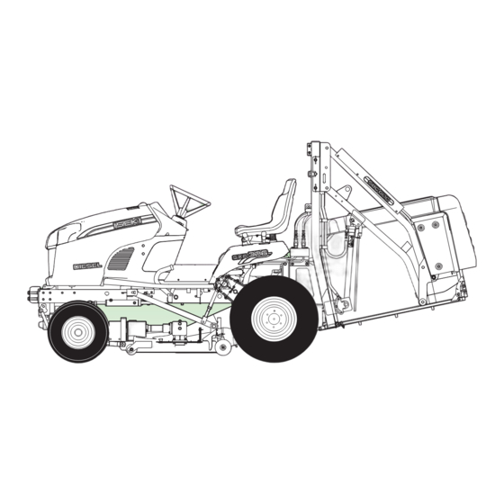
CHAPTER 1. GENERAL INFORMATION 3. EXTERIOR VIEW Fig. 1-4... -
Page 15: Periodic Inspection Table
SERVICE MANUAL FOR SXG323&326 4. PERIODIC INSPECTION TABLE :Inspection, replenishment, and adjustment :Cleaning and washing :Replacement :Consult your dealer. Inspection and servicing intervals Pre- hours of operation Check points Intervals after that Judgement criteria operation 100 150 200 250 300 350 400... -
Page 16: Filling Diagram
CHAPTER 1. GENERAL INFORMATION 5. FILLING DIAGRAM Oil fillers Oil drains Greasing points Fig. 1-5 Ref.No Filling points Lubricants Quantity: litre (imp.gal) Radiator 3.5 (0.77) LLC50% Reserve tank 0.6 (0.13) Engine Engine Oil 2.6 (0.57) Transmission case HST OIL(SHELLDONAX TD) 8.0 (1.76) Chain case (RH) Gear oil (SAE80) - Page 17 SERVICE MANUAL FOR SXG323&326...
-
Page 18: Chapter 2. Disassembly Of Major Components
CHAPTER 2. DISASSEMBLY OF MAJOR COMPONENTS CHAPTER 2. DISASSEMBLY OF MAJOR COMPONENTS 1. GENERAL PRECAUTIONS FOR SEPARATION AND REINSTALLATION 1.1. BEFORE OPERATION 1.2. PRECAUTIONS TO BE FOLLOWED WHEN INSTALLING COMMON PARTS a. Always be safety-conscious in selecting clothes a. Roller or ball bearings to wear and suitable tools to use. - Page 19 SERVICE MANUAL FOR SXG323&326 c. O-rings • O-rings should be coated with grease before • The roll pins installed in the transmission or other installing. parts where much force is applied should be retained with wire. • Installed O-rings should have no slack or twist.
- Page 20 CHAPTER 2. DISASSEMBLY OF MAJOR COMPONENTS i. Other precautions • Be sure not to damage any finished surfaces or parts. •Always refrain from forcing installation. • Each lever knob should be installed coated with an adhesive (SUPER THREE CEMENT TB1702) •...
-
Page 21: Disassembly Of Functional Blocks
SERVICE MANUAL FOR SXG323&326 2. DISASSEMBLY OF FUNCTIONAL BLOCKS 2.1. REMOVAL OF THE MOWER DECK (1) Start the engine and lower the mower deck by (5) Dismount the front linkage from the mower deck. the lift lever. Turn the key switch OFF. -
Page 22: Detaching The Collector
CHAPTER 2. DISASSEMBLY OF MAJOR COMPONENTS 2.2. DETACHING THE COLLECTOR 2.2.1. DETACHING THE HIGH DUMP 2.2.2. DETACHING THE LOW DUMP COLLECTOR COLLECTOR (1) Set the collector lowest position by using lift (1) Set the collector lowest position by using lift and and dump lever. -
Page 23: Removal Of Major Functional Components
SERVICE MANUAL FOR SXG323&326 2.3. REMOVAL OF MAJOR FUNCTIONAL COMPONENTS 2.3.2. REMOVAL OF FLOOR STEP, COVER 2.3.1. REMOVAL OF FENDER(WING) PANEL AND FUEL TANK (1) Disconnect the wire harness of seat and remove (1) Remove the center cover of step. -
Page 24: Removal Of Steering Heel,Meter Panel
CHAPTER 2. DISASSEMBLY OF MAJOR COMPONENTS 2.3.4. REMOVAL OF RADIATOR (4) Disconnect the fuel hose. (5) Remove the fuel tank. (1) Drain the coolant in radiator. (2) Disconnect the radiator hose from engine. (3) Disconnect the fan cover from radiator. (4) Remove the radiator. -
Page 25: Removal Of Engine
SERVICE MANUAL FOR SXG323&326 2.3.5. REMOVAL OF ENGINE (7) Detach the engine from bracket (1) Disconnect the drive shaft from engine. Fig. 2-24 Fig. 2-21 2.3.6. REMOVAL OF REAR AXLE CASE (2) Separate the fan cover from radiator. (3) Disconnect the hydraulic hose and radiator hose (1) Remove the rear tyre. -
Page 26: Removal Of Transmission Case
CHAPTER 2. DISASSEMBLY OF MAJOR COMPONENTS 2.3.7. REMOVAL OF TRANSMISSION CASE (1) Drain the oil in the transmission case. (7) Detach the transmission case from bracket. Fig. 2-29 Fig. 2-27 2.3.8. REMOVAL OF FRONT AXLE CASE AND (2) Disconnect the wire cable of dif-lock from STEERING CYLINDER transmission case. -
Page 27: Reinstallation
SERVICE MANUAL FOR SXG323&326 (4) Detach the front axle from bracket. (5) Connect wire harness. - Glow plug terminals - Thermometer - Oil pressure switch - Starter - Alternator - Fuel cut-off unit (6) Install radiator hoses. (7) Install the air intake pipe,throttle wire,tension arm wire,etc.,and then check that they have been... -
Page 28: Chapter 3. Engine Accessories
CHAPTER 3. ENGINE ACCESSORIES CHAPTER 3. ENGINE ACCESSORIES 1. RADIATOR Take care not to spill antifreeze on painted parts. (1) CONSTRUCTION (3) INSPECTION FOR RADIATOR WATER LEAKS Water leaks are liable to occur at the fitting portion between the upper tank and the core section or between the lower tank and the core section. -
Page 29: Cooling Fan And Belt
SERVICE MANUAL FOR SXG323&326 (4) INSPECTION FOR RADIATOR CLOGIGING (5) VISUAL INSPECTION OF THE EXTERIOR PARTS Inside: When the radiator exterior is corroded, cracked, or Clean the radiator inside as shown below. badly damaged and the radiator core fins are crushed or damaged, replace the radiator. -
Page 30: Air Cleaner
CHAPTER 3. ENGINE ACCESSORIES 3. AIR CLEANER Using compressed air [not exceeding 200 kPa (30 psi)] from the inside of the element, remove loose dirt, grass, chaff, etc. (1) REMOVAL AND REASSEMBLY Be careful not to damage element pleats with air Release clips on the cover. - Page 31 SERVICE MANUAL FOR SXG323&326 (2) INSPECTION Use only clean diesel fuel of cor rect grade. Introduction of water or dirt into the fuel tank or other part of the fuel system can cause repeated plugging of the fuel filter and possible injection pump and injector damage.
-
Page 32: Trouble Shooting
CHAPTER 3. ENGINE ACCESSORIES 5. TROUBLE SHOOTING Problems and probable causes Countermeasures Overheating: Low coolant level Replenish coolant and inspect water leaks. Fatigued pressure valve spring Replace radiator cap. Loose or broken fan belt Adjust belt tension or replace. Oily fan belt Replace. - Page 33 SERVICE MANUAL FOR SXG323&326...
-
Page 34: Chapter 4. Engine
CHAPTER 4. ENGINE CHAPTER 4. ENGINE 1. ENGINE 1.1. SPECIFICATIONS Engine models E3112-G06 E3112-G07 4-cycle, over-head valve, diesel with swirl type combustion Type chambers Cylinder- Bore Stroke mm (in) 3-78.2X78 (3-3.08X3.1) Total displacement cc (cu.in.) 1123 (68.53) Compression ratio 22.5 Rated output ps (kW) at 2600rpm 19.2 (14.1) 21.1 (15.5) -
Page 35: Performance Curves
SERVICE MANUAL FOR SXG323&326 1.2. PERFORMANCE CURVES (1) SXG326 (E3112-G07) Fig. 4-1 (2) SXG323 (E3112-G06) Fig. 4-2... -
Page 36: Inspection And Adjustment
CHAPTER 4. ENGINE 2. INSPECTION AND ADJUSTMENT a. REPLACEMENT OF OIL FILTER 2.1. INSPECTION OF ENGINE OIL Remove the oil filter cartridge from the cylinder block, using a cartridge wrench. • Draw out the level gauge (dip stick) and wipe the end clean. -
Page 37: Inspection And Adjustment Of Valve Clearances
SERVICE MANUAL FOR SXG323&326 Specified valve clearance (cold): • Adjustment: When the deflection is more than specified, ten- sion the belt properly by moving the alternator. 2.3. INSPECTION AND ADJUSTMENT OF VALVE CLEARANCES 2.4. INSPECTION AND ADJUSTMENT OF NOZZLE OPENING PRESSURE AND INJECTION TIMING •... - Page 38 CHAPTER 4. ENGINE • When the pressure is too high, adjust by reduce- (2) Remove the injection pipes. ing shimming thickness for the nozzle, or replace the nozzle assembly. Note: To keep away dust, cap the openings of the in- •...
- Page 39 SERVICE MANUAL FOR SXG323&326 (7) Make sure that fuel ejects from the delivery ・ holder. Turn the crankshaft slowly in correct direction (clockwise viewed from the fan) until fuel ejection stops. The injection timing is just Note: before fuel ejection stops.
-
Page 40: Compression And Unloaded Idling Speeds
CHAPTER 4. ENGINE 2.5. COMPRESSION UNLOADED IDLING SPEEDS (1) Check for idling speeds. (1) Remove the injection pipes. ± (2) Remove an injection nozzle. (2) When the measured value deviates from the specified value, correct with an adjusting bolt. Note: Cap the injection nozzles, injection pump, and injection pipes to avoid dust. -
Page 41: Inspection Of Thermostat
SERVICE MANUAL FOR SXG323&326 Check the bearing unit for run-out. If the run out is more than 0.2 mm (0.008 in.), replace the pump assembly. 2.7. INSPECTION OF THERMOSTAT • Inspection of activating temperatures at which the valve starts to open and opens fully. - Page 42 CHAPTER 4. ENGINE (5) Removal of the rocker shaft assembly. (1) Removal of the cylinder head cover. (6) Removal of the push rods. (7) Removal of the water by-pass hose. (8) Removal of nozzles. (2) Disconnection of the injection piping. •...
- Page 43 SERVICE MANUAL FOR SXG323&326 (1) Removal of the inlet manifold. (2) Removal of the exhaust manifold. (3) Removal of the thermostat housing. (4) Removal of the valves. (2) Inspection of the cylinder head for distortion • Measure the flatness of the bottom surface of the...
- Page 44 CHAPTER 4. ENGINE • Check the valve for play with a dial indicator. If • Press in so that the distance from the cylinder the play exceeds 0.15 mm (0.0059 in.) for the head top to the valve guide end becomes 7mm. inlet valve and 0.2 mm (0.008 in.) for the •...
- Page 45 SERVICE MANUAL FOR SXG323&326 (7) Inspection of valve springs. • Measure the free length of each valve spring with calipers. Note: After lapping, remove the polishing compound completely. (When compressed to 36mm) (6) Inspection of valves. • Put a spring upright on a surface table and meas- •...
-
Page 46: Disassembly
CHAPTER 4. ENGINE (3) Inspection of the rocker arm shaft for wear. • Measure diameter at four points where the shaft bears respective rocker arms. When the deviation exceeds the usable limit, • When wear is in excess of the usable limit, replace the manifold. -
Page 47: Installation Of The Cylinder Head
SERVICE MANUAL FOR SXG323&326 (5)Reassembly of the rocker arm shaft assembly (1) Installation of the cylinder head • Arrange the rocker arms so that the sides where identification markings were put when disas- • Clean the bottom surface of the cylinder head sembled are turned forward. - Page 48 CHAPTER 4. ENGINE • Place the cylinder head softly on the cylinder (4) Installation of the leak hoses. block. • Apply engine oil to the threads of the cylinder head bolts. • Tighten the cylinder head bolts in the sequence as shown in Fig.IV-31 to the specified torque.
-
Page 49: Gear Case
SERVICE MANUAL FOR SXG323&326 (7) Installation of the injection pipes. sure to adjust the valve clearances. • Install injection pipes for respective cylinders (10) Installation of the head cover. and tighten them securely. Note: (8) Install water by-pass hose. The head cover seal and gasket is made of rubber, (9) Adjustment of the valve clearances. -
Page 50: Re-Installation Of The Gear Case
CHAPTER 4. ENGINE Note: Note which bolt is to be installed in which place for later reference and remember to remove the bolts which also tighten the case from behind. Fig. 4-53 • Install the gear case. Specified torque 1.4 - 2.4 kgf・m Fig. -
Page 51: Cylinder Block
SERVICE MANUAL FOR SXG323&326 3.3. CYLINDER BLOCK 3.3.1. EXPLODED VIEW Fig. 4-55... -
Page 52: Disassembly Of The Cylinder Block
CHAPTER 4. ENGINE 3.3.2. DISASSEMBLY OF THE CYLINDER (10) Remove the water pump spacer. BLOCK (11) Remove the oil filter. (1) Install the engine on an engine stand. (12) Remove the oil pan and oil strainer. (13) Clean the cylinder bores of carbon deposit. Remove carbon deposit from the upper part of the cylinder bore with a scraper, taking care not to damage the cylinder walls. -
Page 53: Inspection Of Cylinder Block,Crankshaft, Camshaft
SERVICE MANUAL FOR SXG323&326 (15) Removal of the flywheel. 3.3.3. INSPECTION OF CYLINDER BLOCK, CRANKSHAFT, CAMSHAFT, • Chock the flywheel. AND TAPPETS • Removal of the flywheel. (1) Inspection of the cylinder block • Inspect the cylinder block for damage. - Page 54 CHAPTER 4. ENGINE Fig. 4-65 Fig. 4-63 (2) Inspection of the crankshaft • Check the crankshaft journals for oil clearance. - Measure cylinder bore diameter at a point of 12 to 14 mm (0.47 - 0.55 in.) below the cylinder a.
- Page 55 SERVICE MANUAL FOR SXG323&326 c. Tighten the bearings on the connecting rods to the specified torque. Fig. 4-67 Standard value Usable limit 0.029 - 0.090 mm 0.12 mm f. If the oil clearance of a journal is in excess of the usable limit, replace the bearings with new Fig.
- Page 56 CHAPTER 4. ENGINE oil clearance again. When the clearance exceeds the usable limit ever after new bearing have been installed, polish the pin and use undersize bear- ings. Undersize bearings 0.5; 1.0 mm When the ground-down limit of 1.0 mm (0.039 in.) is enough for correction, replace both crank- shaft and bearings with new ones.
- Page 57 SERVICE MANUAL FOR SXG323&326 (4) Inspection of the camshaft • Check the journals and cams for wear and other damage. A worn or defective shaft should be replaced with a new one. Fig. 4-77 Measure the bore diameter of each bearing. And calculate the difference between the cam journal diameter and bearing bore diameter.
-
Page 58: Inspection Of Pistons And Connecting Rods
CHAPTER 4. ENGINE Standard value Usable limit Replace the tappets, which have clearances in 0.05 - 0.174 mm 0.3 mm excess of the usable limit. Standard value Usable limit If the clearance exceeds the usable limit, replace the thrust plate. 0.02 - 0.062 mm 0.1 mm 3.3.4. - Page 59 SERVICE MANUAL FOR SXG323&326 Standard value Usable limit No.1 compression 0.25 - 0.40 mm 1.5 mm ring No.2 compression 0.25 - 0.40 mm 1.5 mm ring Oil ring 0.25 - 0.40 mm 1.0 mm • Inspection of piston ring clearance in ring grooves.
-
Page 60: Assembly Of Piston And Connecting Rod
CHAPTER 4. ENGINE • Connecting-rod twist • Install a snap ring in one end of the piston pin hole. Find the twist and parallelism between the big end and small end of the connecting rod. • Set the piston and the connecting rod so that the front mark on the piston and "ISEKI"... -
Page 61: Installation Of Crankshaft
SERVICE MANUAL FOR SXG323&326 • The gaps of the ring and ring expander of the oil Note: ring should be set apart 180" from each other. Bearings and bearing fitting surfaces on the cyl- inder block should be free from any foreign ma- tter. -
Page 62: Installation Of Piston/Con-Necting-Rod Assemblies
CHAPTER 4. ENGINE (4) Then install bearing cap seals (B). Drive them in • Install the connecting rod bearing cap having the until they subside 0 - 0.3 mm (0 - 0.012 in.) from same number that the connecting rod has. the cylinder block end. -
Page 63: Installation Of Rear Oil Seal
SERVICE MANUAL FOR SXG323&326 3.3.8. INSTALLATION OF REAR OIL SEAL Fig. 4-101 Fig. 4-99 • Apply silicone compound to the outer circum- Note: ference of the rear oil seal and drive it in evenly Be careful not to damage the O-ring. -
Page 64: Installation Of Front Plate And Gears
CHAPTER 4. ENGINE • Install the crankshaft gear on the crankshaft with the side bearing the front mark turned forward. • Apply engine oil to the camshaft bearing parts and install the camshaft assembly. Then tighten to the specified torque. Specified torque 0.6 - 1.0 kgf・m Fig. - Page 65 SERVICE MANUAL FOR SXG323&326 Fig. 4-107 Fig. 4-109 • Install the injection cam gear assembly. • Installation of the injection pump. • Retain the injection pump cam shaft with the thrust plate and tighten the gear to the specified Tighten the bolts to the specif ied torque in torque.
- Page 66 CHAPTER 4. ENGINE • Install the water by-pass hose. • Install the generator. • Install the fan. Set the fan belt on the fan pulley. Install the spacer and the fan. Fig. 4-111 • Install the oil pan with the recessed part turned forward.
- Page 67 SERVICE MANUAL FOR SXG323&326...
-
Page 68: Chapter 5. Lubrication System
CHAPTER 5. LUBRICATION SYSTEM CHAPTER 5. LUBRICATION SYSTEM 1. GENERAL DESCRIPTION 1.1. LUBRICATION DIAGRAM Fig. 5-1... -
Page 69: Relief Valve
SERVICE MANUAL FOR SXG323&326 1.2. RELIEF VALVE Fig. 5-3 Oil filter * Oil filter cartridge should be replaced with a Fig. 5-2 Relief valve new one after every 300 hours of operation. 1.3. OIL FILTER SPECIFICATIONS CONSTRUCTION AND OPERATION... -
Page 70: Exploded View Of Oil Pump
CHAPTER 5. LUBRICATION SYSTEM 1.4. EXPLODED VIEW OF OIL PUMP Fig. 5-4... -
Page 71: Removal, Disassembly, Inspection And Re-Installation Of Oil Pump
SERVICE MANUAL FOR SXG323&326 2. REMOVAL, DISASSEMBLY, INSPECTION AND RE-INSTALLATION OF OIL PUMP 2.1. REMOVAL OF OIL PUMP Fig. 5-6 Fig. 5-5 2.2. DISASSEMBLY OF OIL PUMP 2.3. INSPECTION Fig. 5-7... -
Page 72: Installation Of Oil Pump
CHAPTER 5. LUBRICATION SYSTEM Fig. 5-10 Fig. 5-8 3.2. INSTALLATION OF OIL FILTER 2.4. INSTALLATION OF OIL PUMP Fig. 5-9 Fig. 5-11 3. OIL FILTER 3.1. REMOVAL OF OIL FILTER Fig. 5-12... - Page 73 SERVICE MANUAL FOR SXG323&326...
-
Page 74: Chapter 6. Cooling System
CHAPTER 6. COOLING SYSTEM CHAPTER 6. COOLING SYSTEM 1. COOLING SYSTEM DIAGRAM Fig. 6-1 *In this section, only the thermostat and the 2.3. INSPECTION OF THERMOSTAT water pump, which are directly mounted on the engine, are explained. About the radiator, refer •... -
Page 75: Water Pump
SERVICE MANUAL FOR SXG323&326 Replace the thermostat whose specified temper- atures deviate from specified values. Note: - Keep in mind that the valve reaction to tempera- • Remove the cooling fan and pulley. ture change is sometimes delayed by 3 to 5 min- utes. -
Page 76: Chapter 7. Fuel System
CHAPTER 7. FUEL SYSTEM CHAPTER 7. FUEL SYSTEM 1. INJECTION PUMP CONSTRUCTION The illustrations used in this section show the 3-cylinder type. The construction is the same as that of the 2-cylinder type except in cylinder number. Fig. 7-1 Specifications Pump type NP-PFR2MD60/1NP6 6.0 mm, counter-clockwise leading: 12 mm (0.472 in.) -
Page 77: Removal, Disassembly, Inspection, Re-Assembly, And Installation
SERVICE MANUAL FOR SXG323&326 2. REMOVAL, DISASSEMBLY, INSPECTION, RE-ASSEMBLY, AND INSTALLATION The injection pump is a precision component, so handle it carefully. Before disassembling the pump, wash it clean of dust and oil. While disassembling, put aside the disassembled parts in order of disassembly and in accordance with respective cylinders. -
Page 78: Removal Of Injection Pump
CHAPTER 7. FUEL SYSTEM 2.1. REMOVAL OF INJECTION PUMP Remove the injection pipes. Remove the injection pump side cover. Then remove the control rack along with the starting spring, setting spring, and control link out of the injection pump. Remove the tightening bolts. 2.2. - Page 79 SERVICE MANUAL FOR SXG323&326 NOTE: The control sleeve cannot be removed without shifting the control rack in the center position. Fig.7-11 11) Hold pump housing (1) in a vise and remove the de- livery valve holder from the sleeve flange.
-
Page 80: Inspection
CHAPTER 7. FUEL SYSTEM Control rack Replace a control rack which is bent or has abnormally worn teeth. Fig. 7-14 NOTE: Never change the combination of each plunger and plunger barrel. Fig. 7-16 4) Replace a control sleeve whose recess, where the 15) The sleeve flange can be removed with a special tool. -
Page 81: Re-Assembly
SERVICE MANUAL FOR SXG323&326 2.4. RE-ASSEMBLY Re-assemble the injection pump in reverse order of disassembly, taking the following precautions. Tighten the delivery holder to the specified torque. Specified torque 4.0 - 4.5 kgf m Apply adhesive to the threads of the four bolts (66) which tighten the pump housing plate (65). -
Page 82: Injection Nozzles And Holders
CHAPTER 7. FUEL SYSTEM Install the shim with the chamfered side turned to- After installation, make sure that the control rod wards the tappet. moves smoothly. 3. INJECTION NOZZLES AND HOLDERS 3.1. REMOVAL OF INJECTION NOZZLES AND HOLDERS Removal of the injection pipes and leak-off pipes. After removing the injection pipes, cap the openings of the delivery holders, nozzles, and injection pipes. -
Page 83: Disassembly And Washing Of Injection Nozzles
SERVICE MANUAL FOR SXG323&326 But it can be considered to be normal if the spraying pat- 3.3. DISASSEMBLY AND WASHING OF INJECTION tern is focused and free from scattering. NOZZLES Fig. 7-26 Injection-starting pressure Injection-starting pressure should be 120 kgf/cm (1707 psi). -
Page 84: Installation Of Injection Nozzles And Holders
CHAPTER 7. FUEL SYSTEM When a nozzle is found functioning poorly through spray 3.4. INSTALLATION OF INJECTION NOZZLES AND test, wash it. If its original function is not restored by HOLDERS washing, replace it. Before installation, wash all parts in clean diesel fuel Nozzle washing or cleansing oil. -
Page 85: Governor
SERVICE MANUAL FOR SXG323&326 The floating arm end is connected with a pin to the 4. GOVERNOR control link, which is connected with the control rack 4.1. GOVERNOR CONSTRUCTION of the injection pump. Flyweights are installed on the injection pump cam... - Page 86 CHAPTER 7. FUEL SYSTEM Be careful not to hit the nozzle body with a wrench, which may cause fuel leakage. Place the packing ring in position and tighten the joint nut to the specified torque. Specified torque 2 - 2.5 kgf m Install the injection pipe and leak-off pipe and tighten them to the specified torque.
-
Page 87: Governor Operation
SERVICE MANUAL FOR SXG323&326 4.2. GOVERNOR OPERATION 1) The control lever is released in the engine starting position and is set in the idling position by the return spring. In this state no centrifugal force is applied to the governor, so the control rack of the injection pump is shifted by the starting spring to the position for increased fuel supply. -
Page 88: Chapter 8. Transmission And Related Parts
CHAPTER 8. TRANSMISSION AND RELATED PARTS CHAPTER 8. TRANSMISSION AND RELATED PARTS BRAKE ENGINE HST UNIT 23T 48T FRONT PTO (OPTION) 45T (1750rpm at engine 2600rpm) 12T 29T 11T Fig. 8-1 ENGINE HST UNIT 23T 48T 45T FRONT PTO (OPTION) (1750rpm at engine 2600rpm) 12T... - Page 89 SERVICE MANUAL FOR SXG323&326 Fig. 8-3 Fig. 8-4...
- Page 90 CHAPTER 8. TRANSMISSION AND RELATED PARTS Fig. 8-5 Fig. 8-8 Fig. 8-6 Fig. 8-9 Fig. 8-7 Fig. 8-10...
- Page 91 SERVICE MANUAL FOR SXG323&326 Usable limit 2.2mm Fig. 8-11 Brake arm Fig. 8-15 Fig. 8-12 Fig. 8-13...
- Page 92 CHAPTER 8. TRANSMISSION AND RELATED PARTS UGE TYPE 7. DIF-LOCK ADJUSTMENT 8 notches Brake cable Brake rod Fig. 8-15 ADJUST BRAKE ROD (1) Depress the brake pedal until the stopper. Fig. 8-16 (2) Adjust the length of brake rod so that distance of (1) Make sure the Arm/Diff(4) to move spring is 0.3mm.
- Page 93 SERVICE MANUAL FOR SXG323&326...
-
Page 94: Chapter 9. Rear Axle
CHAPTER 9. REAR AXLE CHAPTER 9. REAR AXLE 1. CONSTRUCTION Fig. 9-1 DISASSEMBLY (3) Remove the gear and chain and tension plate. (1) Drain the oil in the rear axle case. Fig. 9-4 Fig. 9-2 (4) Detach the rear axle case from chassis. (5) Remove the snap ring on the wheel shaft. - Page 95 SERVICE MANUAL FOR SXG323&326 (6) Remove the wheel shaft. (9) Remove the snap ring on shaft. Fig. 9-6 Fig. 9-9 (7) Remove the snap ring on the bearing. (10) Remove the shaft from case. Fig. 9-7 Fig. 9-10 (8) Remove the bearing from the rear axle case.
-
Page 96: Chapter 10. Hydrostatic Transmission
CHAPTER 10. HYDROSTATIC TRANSMISSION CHAPTER 10. HYDROSTATIC TRANSMISSION 1. CONSTRUCTION AND NAMES OF MAJOR COMPONENTS Fig.10-1... -
Page 97: Operating Diagram Of Hst
SERVICE MANUAL FOR SXG323&326 2. OPERATING DIAGRAM OF HST Fig. 10-2... -
Page 98: Function
CHAPTER 10. HYDROSTATIC TRANSMISSION 3. FUNCTION 3.1. VARIABLE TYPE PUMP Pistons are housed in the cylinder block, which is connected to the engine and revolves as the engine does, while the slant board does not. When the slant board and shaft are perpendicular to each other, cylinder displacement volumes A and B do not vary, so no delivery or suction takes place. - Page 99 SERVICE MANUAL FOR SXG323&326 Fig. 10-5 Fig. 10-6...
- Page 100 CHAPTER 10. HYDROSTATIC TRANSMISSION Fig. 10-7...
-
Page 101: Disassembly And Reassembly
SERVICE MANUAL FOR SXG323&326 Fig. 10-8 4. DISASSEMBLY AND REASSEMBLY... - Page 102 CHAPTER 10. HYDROSTATIC TRANSMISSION 4.3.
- Page 103 SERVICE MANUAL FOR SXG323&326...
-
Page 104: Disassembly
CHAPTER 10. HYDROSTATIC TRANSMISSION 4.4. DISASSEMBLY (2) Remove the cylinder block assembly. (1) Remove the port block. a. Remove the bolts. Fig. 10-12 Components of the cylinder block assembly (Both blocks have the same components.) Fig. 10-9 • Cylinderblock ......1 b. - Page 105 SERVICE MANUAL FOR SXG323&326 Fig.10-14 Fig. 10-16 (4) Remove motor-side thrust bearing from the b. Remove the snap-ring and hit the end of the shaft case . with a plastic hammer as shown in the figure blow and extract the shaft from the case .
- Page 106 CHAPTER 10. HYDROSTATIC TRANSMISSION Fig. 10-20 Fig. 10-18 (7) Disassembly of the port block b. Remove the snap-ring which is inside the case, and hit the end of the shaft with a plastic ham- a. Remove the plug for the check valve and take out mer as shown in the figure below in order to the springs and poppets out of the port block .
-
Page 107: Criteria For Replacing Worn Parts
SERVICE MANUAL FOR SXG323&326 4.5. CRITERIA FOR REPLACING WORN PARTS... -
Page 108: Precaution Before Reassembly
CHAPTER 10. HYDROSTATIC TRANSMISSION 4.6. PRECAUTION BEFORE REASSEMBLY a. Wash disassembled parts in fresh cleansing oil and blow them with compressed air. b. Handle the cleaned parts carefully to avoid dam- age such as dents, scratches, etc. c. All removed sealing parts should be discarded and replaced with new ones. - Page 109 SERVICE MANUAL FOR SXG323&326 • Reassembly of the motor side shaft (3) Reassembly of the slant board and thrust bearing a. Install the motor shaft assembly, which is com- a. Install the thrust bearing into the case . posed of the shaft ball bearing and snapring into the case and retain the shaft with the snap-ring .
- Page 110 CHAPTER 10. HYDROSTATIC TRANSMISSION Fig. 10-31 Fig. 10-29 b. Install the valve sub-assembly . (4) Installation of the cylinder blocks Apply grease to the valve ahead of time to pre- a. Install the cylinder block assembly, which is vent it from falling. composed of the cylinder block pistons springs and spring holders respectively onto the motor c.
- Page 111 SERVICE MANUAL FOR SXG323&326 Fig. 10-33 e. After being reassembled, make sure that the shafts turn smoothly using an adjustable end wrench. Fig. 10-35 Fig. 10-34...
- Page 112 CHAPTER 10. HYDROSTATIC TRANSMISSION 4.8. PRECAUTIONS FOR REASSEMBLY a. Installation of shaft bearings Press in the bearings using the jigs mentioned in the drawing below. Fig. 10-37 c. Swash plate (slant board) assembly • Press the bush into the slant board so that the bush end becomes flush with the surface of the swash plate.
- Page 113 SERVICE MANUAL FOR SXG323&326 e. Installation of oil seals g. Pressed-in parts in the port block • Press the oil seal into the cover until the oil seal Note: end becomes flush with the cover surface. • The oil seal should be installed with the dust lip turned outward.
-
Page 114: List Of Major Components Of Hist
CHAPTER 10. HYDROSTATIC TRANSMISSION 4.9. LIST OF MAJOR COMPONENTS OF HIST Fig. 10-44 4.10. PRECAUTIONS FOR INSTALLATION OF 4.11. PRECAUTIONS AFTER INSTALLATION HST UNIT OF HST UNIT (1) STARTING (1) INSTALLATION OF SHAFTS a. Fill the HST case with working fluid. a. -
Page 115: Adjustment Of Hist
SERVICE MANUAL FOR SXG323&326 acceralate to the specified speed. 5. ADJUSTMENT OF HIST (2) OIL TEMPERATURE It is a very important factor at what temperature Warning: a hydraulic system operates. High operating tem- After a long time of use, the neutral position of... - Page 116 CHAPTER 10. HYDROSTATIC TRANSMISSION f. When the lawn mower creeps forward, tilt the k. Next, align both HST pedals in height by adjust- adjust nut slightly toward A and when ing the effective length of the HST rod with the creeps reverse, tilt toward B by manipulating the two lock nuts.
- Page 117 SERVICE MANUAL FOR SXG323&326...
-
Page 118: Chapter 11. Hydraulic System
CHAPTER 11. HYDRAULIC SYSTEM CHAPTER 11. HYDRAULIC SYSTEM 1. HYDRAULIC SYSTEM DIAGRAMS X X Fig. 11-1... - Page 119 SERVICE MANUAL FOR SXG323&326 Steering control Fig. 11-2...
-
Page 120: Inspection Of Major Components
CHAPTER 11. HYDRAULIC SYSTEM 2. INSPECTION OF MAJOR COMPONENTS parts with new ones. 2.1. SUCTION FILTER Delivery pressure: 6.87Mpa (70 kgf/cm 2) with fluid heated at 50° C (Maximum pressure: 85 kgf/cm 2 ) The filter is installed under the transmission case. It has a reusable wire element, which should be washed clean periodically. -
Page 121: Relief Metal (Support)
SERVICE MANUAL FOR SXG323&326 2.4. RELIEF METAL (support) 6.0-6.5Mpa Relief pressure (61.2-66.3kgf/cm2) 2.5. OIL FILTER (Relief metal (support) The filter cartridge is attached on the HST unit. Bypass relief valve in the base 1.5Mpa Opening pressure (1.5kgf/cm2) Replace the cartridge with a new one after the initial 50 hours of operation and the after every 200hours of operation. -
Page 122: Chapter 12. Power Steering System
CHAPTER 12. POWER STEERING SYSTEM CHAPTER 12. POWER STEERING SYSTEM 1. CONSTRUCTION Control(steering) Pump port(A) Tank port(B) L P Left port(E) T R E Right port(D) E port(C) CYLINDER ASSY CONTROLLER L R /STREERING ASSY 32cc/rev RELEAF PRESSURE: 6.0∼6.5MPa P T... -
Page 123: Working Principle
SERVICE MANUAL FOR SXG323&326 2. WORKING PRINCIPLE Fig. 12-2 Fig. 12-4 (when the steering wheel is turned to right) Fig. 12-3: when the steering wheel is in neutral Fig. 12-5 (when the steering wheel is turned to left) -
Page 124: Major Troubles And Causes, And Countermeasures
CHAPTER 12. POWER STEERING SYSTEM 3. MAJOR TROUBLES AND CAUSES, AND COUNTERMEASURES... - Page 125 SERVICE MANUAL FOR SXG323&326...
- Page 126 CHAPTER 12. POWER STEERING SYSTEM...
- Page 127 SERVICE MANUAL FOR SXG323&326...
-
Page 128: Chapter 13. Electrical Accessories
CHAPTER 13. ELECTRICAL ACCESSORIES CHAPTER 13. ELECTRICAL ACCESSORIES 1. ELECTRICAL COMPORNENS AND WIRE HARNESS 1) UE TYPE 2) UGE TYPE RELAYS Fig. 13-1 Fig. 13-3 Fig. 13-2 Fig. 13-4 FUSE Fig. 13-6 Fig. 13-5... - Page 129 SERVICE MANUAL FOR SXG323&326 3) ALL TYPE Fig. 13-7 Fig. 13-9 Fig. 13-8 Engine Fig. 13-10 Fig. 13-11...
-
Page 130: Wiring Diagram (E Type)
CHAPTER 13. ELECTRICAL ACCESSORIES 2. WIRING DIAGRAM (E TYPE) Fig. 13-12... -
Page 131: Wiring Diagram (Ge Type)
SERVICE MANUAL FOR SXG323&326 3. WIRING DIAGRAM (GE TYPE) Fig. 13-13... -
Page 132: Starter
CHAPTER 13. ELECTRICAL ACCESSORIES 4. STARTER Fig. 13-14... -
Page 133: Removal And Disassembly Of Starter
SERVICE MANUAL FOR SXG323&326 4.2. REMOVAL AND DISASSEMBLY OF STARTER REMOVAL OF STARTER 1) Remove the negative (-) battery cable. 2) Remove the starter wiring. • Disconnect the wire harness from terminal 30 by removing the nut. Fig. 13-17 • Remove the connector from terminal 50. - Page 134 CHAPTER 13. ELECTRICAL ACCESSORIES armature coil core. If there is no continuity, the • Measure the commutator diameter with vernier armature coil is normal. calipers. Standard value Usable limit 30 mm 29 mm Fig. 13-20 2) Inspection of armature coil for short circuit •...
- Page 135 SERVICE MANUAL FOR SXG323&326 8) Inspection of the brush holder • Inspect for insulation across positive (+) side and negative (-) side of the brush holder. If there is no continuity, the brush holder is normal. Fig. 13-26 6) Inspection of the brushes •...
-
Page 136: Reassembly Of Starter
CHAPTER 13. ELECTRICAL ACCESSORIES 4.4. REASSEMBLY OF STARTER 1) Installation of the armature • Apply grease to the armature bearing and then install the armature on the starter yoke. 2) Installation of the brushes and brush holder Fig. 13-32 • Lift up and hold the spring and install the brush. Fig. -
Page 137: Inspection Of The Starter After Removal From The Tractor
SERVICE MANUAL FOR SXG323&326 5) Installation of the gear and clutch • In the state of the pull-in test, the gear should remain pushed out when the lead is disconnected • Install the clutch assembly on the starter hous- from terminal C. -
Page 138: Installation Of The Starter
CHAPTER 13. ELECTRICAL ACCESSORIES Fig. 13-43 2) Braking test Install the starter on a test bench and apply brake. Measure each value while the starter is thus prevented from spinning. Each value should be as shown below: Voltage 8.0 V Current 230A or less at 1180 rpm or over... -
Page 139: Alternator
SERVICE MANUAL FOR SXG323&326 5. ALTERNATOR 5.1. EXPLOTED VIEW, SPECIFICATIONS, AND PERFORMANCE CURVES Fig. 13-45 Fig. 13-46... - Page 140 CHAPTER 13. ELECTRICAL ACCESSORIES Fig. 13-48 Fig. 13-47...
- Page 141 SERVICE MANUAL FOR SXG323&326 Fig. 13-51 Fig. 13-49 f. Removal of the brushes d. Removal of the 1C regulator Remove the four nuts and bushes which tighten Remove the three screws which tighten the 1C the drive end frame and rear end frame. Then the regulator.
-
Page 142: Inspection
CHAPTER 13. ELECTRICAL ACCESSORIES Note: The bearing is a high speed type, so be sure to use a specified one by ISEKI when replacing. Never give it shock. k. Removal of the baring which is installed on the slip ring side Remove the bearing using a puller as illustrated. - Page 143 SERVICE MANUAL FOR SXG323&326 If it is smeared with oil, clean with alcohol- c. Continuity test of the stator coils soaked cloth. Check for continuity across respective coil ter- b. Continuity test of the rotor coil minals with a tester. If there is no continuity, re- place the stator.
- Page 144 CHAPTER 13. ELECTRICAL ACCESSORIES Note: the brush holder. If the length is less than the The rectifier cannot bejudged by the resistance usable limit, replace. value shown in forward direction, because the diode shows greatly different forward current flow in accordance with voltage applied, that is, the tester type and resistance range applied greatly affect resistance reading.
-
Page 145: Re-Assembly
SERVICE MANUAL FOR SXG323&326 j. Inspection of the IC regulator Fig. 13-67 • Connect the removed 1C regulator, variable DC power supply, voltmeter, and a lamp as illustrat- ed. (Keep SW1 and SW2 turned off.) • Set the power supply at 12V . -
Page 146: Glow Plugs
CHAPTER 13. ELECTRICAL ACCESSORIES Fig. 13-70 Fig. 13-69 Note: • The clearance between the brush holderandthe 2) Installation of the brush holder connector should be 1 mm or more. • Rubberpackingfor the brush holder should not Install the brush holder sideways along with the be deformed or pinched. -
Page 147: Removal, Inspection, And Re-Assembly
SERVICE MANUAL FOR SXG323&326 6.2. REMOVAL, INSPECTION, AND RE-ASSEMBLY a. Troubleshooting b. Removal electrode. If there is no resistance, it indicates a short circuit, so replace the glow plug. If the re- • Remove the connector by loosening the glow sistance is infinite, it shows that pre-heating coil plug nut installed on the cylinder head. - Page 148 CHAPTER 1 CHAPTER 2 CHAPTER 3 CHAPTER 4 CHAPTER 5 CHAPTER 6 CHAPTER 7 CHAPTER 8 MOWER DECK MOWER DECK SCMB48 & SCMA54 SCMB48 & SCMA54...
- Page 150 MOWER DECK CONTENTS CONTENTS ............................3 CHAPTER 1. FOR SAFETY LABELS ....................5 CHAPTER 2. SPECIFICATIONS ...................... 7 CHAPTER 3. ATTACHING AND DETACHING THE MOWER DECK ..........9 1. ATTACHING THE MOWER DECK ..................... 9 2. DETACHING THE MOWER DECK ..................10 CHAPTER 4.
- Page 151 SERVICE MANUAL FOR SXG323&326...
-
Page 152: Chapter 1. For Safety Labels
CHAPTER 1. FOR SAFETY LABELS CHAPTER 1. FOR SAFETY LABELS SAFETY LABELS SCMB48 & 54... - Page 153 SERVICE MANUAL FOR SXG323&326 Shut off the engine and remove the starter key before performing maintenance or repair work. ・Maintenance of the caution labels - The labels should always be clearly seen, that is, nothing should obscure them. - When they have become dirty, wash them with soapy water and wipe off with soft cloth.
-
Page 154: Chapter 2. Specifications
CHAPTER 2. SPECIFICATIONS CHAPTER 2. SPECIFICATIONS Models SCMB48 SCMA54 Type Rotary mower with rear discharge Cutting width 1220mm 1372mm Number of blades Blade driving method Shaft drive Overlap of Blades 112mm 60mm Dimensions Overall length 885mm Overall width 1275mm 1430mm Overall height 380mm 395mm... - Page 155 SERVICE MANUAL FOR SXG323&326 1. SCMB48 & SCMA54 (1) Mower deck (2) Drive shaft (3) Pulley cover (4) Joint cover (5) Yoke cover (6) Water hose plug (7) Carry handle with step (8) V-belt (9) Input bearing case (10) Output bearing case...
-
Page 156: Chapter 3. Attaching And Detaching The Mower Deck
CHAPTER 3. ATTACHING AND DETACHING THE MOWER DECK CHAPTER 3. ATTACHING AND DETACHING THE MOWER DECK 1. ATTACHING THE MOWER DECK Warning: When attaching or detaching the mower deck to the lawn mower: · Place the lawn mower on level, hard ground. ·... -
Page 157: Detaching The Mower Deck
SERVICE MANUAL FOR SXG323&326 a. Start the engine and push down the rear half (u) the lift lever(1) to raise the mower link in the highest position. Important: · When installing and removing the mower deck, b. Set the gauge wheels(3) of the mower deck in turn clockwise(-) the high adjust dial(9) fully to the lowest position. -
Page 158: Chapter 4. Mower Operation
CHAPTER 4. MOWER OPERATION CHAPTER 4. MOWER OPERATION Caution: · Become familiar with haw to operate the lawn mower and understand safety instructions by reading this manual carefully. · Make sure that all safety covers and guards are installed in position. ·... -
Page 159: Starting Mowing Operation
SERVICE MANUAL FOR SXG323&326 3. STARTING MOWING OPERATION a. Start the engine and turn the throttle lever to the intermediate position between the low speed (t) and high speed (r) positions. d. Push down the HST forward travel pedal gradually to drive the lawn mower into the working site. -
Page 160: Emergency Stop
CHAPTER 4. MOWER OPERATION Warning: · When the operator leaves the seat, the safety system · As soon as the PTO lever is shifted to the ON automatically stops the engine. When leaving the lawn ( ) Position, the mower blades start rotating mower to remove obstacles such as twigs, pebbles, etc. - Page 161 SERVICE MANUAL FOR SXG323&326 Important: i. If turf damage by the tyres could result, wait until the · Be sure to mow at full throttle (r). grass and land have dried sufficiently. · Choose an adequate traveling speed in ii. Wet grass requires a higher grass cutting height...
- Page 162 CHAPTER 4. MOWER OPERATION · Be sure to mow at full throttle. · Choose an adequate traveling speed in accordance with height of grass to be cut. · Low cutting height will lead to poor mowing efficiency and rapid blade wear. ·...
- Page 163 SERVICE MANUAL FOR SXG323&326...
-
Page 164: Chapter 5. Inspection And Maintainance Of Major Parts
CHAPTER 5. INSPECTION AND MAINTAINANCE OF MAJOR PARTS CHAPTER 5. INSPECTION AND MAINTAINANCE OF MAJOR PARTS Caution: • When servicing the lawn mower, place it on level, hard ground. b. Check to see if a small amount of oil overflows •... -
Page 165: Inspection And Replacement Of Front Belt
SERVICE MANUAL FOR SXG323&326 2. INSPECTION AND REPLACEMENT OF b. Check the belt for damage and dirt. FRONT BELT If it is smeared with oil or dirt, or wet with water, a. Remove the pulley cover (1) installed on the wipe it clean with a dry cloth. - Page 166 CHAPTER 5. INSPECTION AND MAINTAINANCE OF MAJOR PARTS • Low cutting height or the operation just after soil b. When these blades are not at right angles to has been applied will wear blades rapidly. The each other, straighten them by following ways. blades should be checked more frequently.
-
Page 167: Inspection Of Gauge Wheels
SERVICE MANUAL FOR SXG323&326 4. INSPECTION OF GAUGE WHEELS 6. CLEANING OF MOWER DECK As the gauge wheels are installed on the rear ends of the mower deck, they are more a. Remove belt cover, and clear the grass and dust... -
Page 168: Filling Diagram
CHAPTER 5. INSPECTION AND MAINTAINANCE OF MAJOR PARTS 7. FILLING DIAGRAM All the shafts mentioned below have grease fitting on their end. Grease them up periodically. The gear case should also be serviced periodically for oil replenishment and replacement. Ref. No. Filling points Lubricants Quantity... -
Page 169: Periodical Inspection Table
SERVICE MANUAL FOR SXG323&326 INSPECTION AND MAINTENANCE OF MAJOR PARTS 8. PERIODICAL INSPECTION TABLE :Inspection, replenishment, and adjustment : Cleaning and washing : Replacement Inspection and servicing Check points intervals (hours of operation) Intervals after that Judgement criteria 50 100... -
Page 170: Storage Of Mower Deck
CHAPTER 5. INSPECTION AND MAINTAINANCE OF MAJOR PARTS 9. STORAGE OF MOWER DECK When the mower deck is to be stored for a long period of time, service the deck as mentioned below before storing it. a. Clean the mower deck. Take special care to remove grass and dirt from the blades and underside of the mower deck. - Page 171 SERVICE MANUAL FOR SXG323&326...
-
Page 172: Chapter 6. Disassembly And Reassembly Of Gear Box
CHAPTER 6. DISASSEMBLY AND REASSEMBLY OF GEAR BOX CHAPTER 6. DISASSEMBLY AND REASSEMBLY OF GEAR BOX (1) As for the detachment of the mower deck from the lawn mower. (2) Remove the belt covers and other necessary parts to check the belts and other components for wear or damage or inspect or service each part if required. - Page 173 SERVICE MANUAL FOR SXG323&326 3) Gear box (left hand)
-
Page 174: Disassembly And Reassembly
CHAPTER 6. DISASSEMBLY AND REASSEMBLY OF GEAR BOX f. Inspect the disassembled parts for items men tined 2. DISASSEMBLY AND REASSEMBLY below and replace defective parts with new ones. a. Detach the gear case from mower deck. b. Remove the bolts and metal cover. - Abnormal wear and flaws of bevel gears. - Page 175 SERVICE MANUAL FOR SXG323&326 SCMB48 & 54 Front Belt and Belt tension Blade and Blade hub...
-
Page 176: Chapter 7. Inspection Of Mower Deck Scma Type
CHAPTER 7. INSPECTION OF MOWER DECK SCMA TYPE CHAPTER 7. INSPECTION OF MOWER DECK SCMA TYPE INTRUCTION FOR check and adjustment of SCMA54/48 SHAFT DRIVE Instruction for check 1. To loosen NUT x 5pcs, and to remove BELT COVER. Check points 1. - Page 177 SERVICE MANUAL FOR SXG323&326 1. Inspection and adjustment of COUPLING 2. To put 3 x SNAP RING beside the groove to make space to move COUPLING. 3. To check if 3 x COUPLING can be moved by hand or not.
- Page 178 CHAPTER 7. INSPECTION OF MOWER DECK SCMA TYPE 3 Adjust height and angle of METAL/OUTPUT with SHIM to correct alignment of shaft. FYI: Standard thickness of SHIM will be 1mm for both sides. 4 If the shaft does not meet in horizontal direction, disassemble METAL/OUTPUT and ream 4 fitting holes from 9 to 11mm.
- Page 179 SERVICE MANUAL FOR SXG323&326 1 Loosen TENSION ROD to loosen belt. 2 Loosen NUT for fixing METAL/OUTPUT and move COUPLING/A forward. At this time, scrap the old type SHIM. 3 Loosen 8 x NUT for METAL/BLADE/LH(LH gearbox) and METAL/BLADE/RH (RH gearbox).
-
Page 180: Chapter 8. Troubleshooting
CHAPTER 8. TROUBLESHOOTING CHAPTER 8. TROUBLESHOOTING Troubles Presumable causes Remedies • Improper discharging • Front PTO belts and drive • Check belt and correct. • Blades are installed upside down. • Re-install them correctly. • Grass is too moist. • Wait until grass becomes dry. •... - Page 181 SERVICE MANUAL FOR SXG323&326 Troubles Presumable causes Remedies • Excessive noise and • Clogged grass inside of mower or • Clean. vibration foreign matter caught in a pulley • Broken belt • Replace it with a new one. • Tension of timing belt is poor.
- Page 182 CHAPTER 1 CHAPTER 2 CHAPTER 3 CHAPTER 4 CHAPTER 5 CHAPTER 6 CHAPTER 7 CHAPTER 8 COLLECTOR COLLECTOR SBC600X & SBC550X SBC600X & SBC550X...
- Page 184 COLLECTOR CONTENTS CONTENTS ............................3 CHAPTER 1. SAFETY LABELS ....................... 5 CHAPTER 2. SPECIFICATIONS ...................... 7 CHAPTER 3. NAME OF MAJOR COMPONENTS ................9 1. SBC600X-HQE4 (High dump collector) ..................9 2. SBC550X-LE4 (Low dump collector) ..................9 CHAPTER 4. DETACHING AND ATTACHING THE COLLECTOR ..........11 1.
- Page 185 SERVICE MANUAL FOR SXG323&326...
-
Page 186: Chapter 1. Safety Labels
CHAPTER 1. SAFETY LABELS CHAPTER 1. SAFETY LABELS High dump collector Low dump collector • Maintenance of the caution labels - The labels should always be clearly seen, that is, nothing should obscure them. - When they have become dirty, wash them with soapy water and wipe off with soft cloth. - If any of them are torn or lost, order new labels from your dealer. - Page 187 SERVICE MANUAL FOR SXG323&326 (1) Link caution label (Code No. 8664-905-003-0) (4) Hot-part caution label (Code No. 8595-901-007-0) Stay clear of the container rear frame while the close of the rear door. (5) Discharge label (Code No. 8595-901-005-0) Stay clear of the collector frame while the container dumping.
-
Page 188: Chapter 2. Specifications
CHAPTER 2. SPECIFICATIONS CHAPTER 2. SPECIFICATIONS SPECIFICATIONS... - Page 189 SERVICE MANUAL FOR SXG323&326...
-
Page 190: Chapter 3. Name Of Major Components
CHAPTER 3. NAME OF MAJOR COMPONENTS CHAPTER 3. NAME OF MAJOR COMPONENTS 1.SBC600X-HQE4 (High dump collector) (1) Collector frame (2) Container (3) Lift link (4) Dump link (5) Lift cylinder (6) Dump cylinder (7) Lift hose (8) Dump hose (9) Container limit sensor (10) Container cover (11) Side cover (12) Rear cover... - Page 191 SERVICE MANUAL FOR SXG323&326...
-
Page 192: Chapter 4. Detaching And Attaching The Collector
CHAPTER 4. DETACHING AND ATTACHING THE COLLECTOR CHAPTER 4. DETACHING AND ATTACHING THE COLLECTOR Warning: When attaching or detaching the collector to the lawn mower: · Place the lawn mower on level, hard ground. · Apply the parking brake securely. ·... -
Page 193: Attaching The High Dump Ollector (Sbc600X-Hqe4)
SERVICE MANUAL FOR SXG323&326 m. Move the container ASSY (2) which is put on the collector base ASSY (3) backward slowly to separate from the lawn mower. n. Insert the pin (16x65) COMP (14) in the holes of the upper frame COMP (16), and put the hairpin (8) to the pin (16x65) COMP (14). -
Page 194: Detaching The Low Dump Collector (Sbc550X-Le4)
CHAPTER 4. DETACHING AND ATTACHING THE COLLECTOR SBC600XH & SBC550XL c. Remove Nut (M8) (3) and pin (20x410) COMP 3. DETACHING THE LOW DUMP (2) and hook plate (1) from the collector frame COLLECTOR (SBC550X-LE4) (4). 1) In case of detaching the collector ASSY a. - Page 195 SERVICE MANUAL FOR SXG323&326...
-
Page 196: Chapter 5. Collector Operation
CHAPTER 5. COLLECTOR OPERATION CHAPTER 5. COLLECTOR OPERATION 3. INSPECTION BEFORE OPERATION 1. BERORE OPERATION • Before operating, inspect the points that follow. Caution: · Become familiar with how to operate the lawn mower and understand safety instructions by reading this manual carefully. -
Page 197: Cleaning A Collector
SERVICE MANUAL FOR SXG323&326 4. CLEANING A COLLECTOR If net of container is clogged with grass, the collecting power would go down. Clean the net of container frequently. Danger: It is a danger to operate the lawn mower with damaged rear net. Repair it or replace it with a new one. -
Page 198: Chapter 6. Inspection And Maintainance Of Major Parts
CHAPTER 6. INSPECTION AND MAINTAINANCE OF MAJOR PARTS CHAPTER 6. INSPECTION AND MAINTAINANCE OF MAJOR PARTS 1. INSPECTION OF CYLINDER (1) lock nut (2) adjust adapter a. Cylinder of collector(SBC550X-L) can be adjusted its length. b. Adjust the length of cylinder so that its length is the shortest with collector located lowest position. -
Page 199: Filling Diagram
SERVICE MANUAL FOR SXG323&326 3. FILLING DIAGRAM Grease up the points mentioned below periodically. SBC600X-HQE4 (High dump collector) SBC550X-LE4 (Low dump collector) -
Page 200: Periodical Inspection Table
CHAPTER 6. INSPECTION AND MAINTAINANCE OF MAJOR PARTS 4. PERIODICAL INSPECTION TABLE SBC600X-HQ and SBC550X-L : Inspection, replenishment, and adjustment : Cleaning and washing : Replacement : Consult your dealer. Inspection and servicing Intervals Judgement intervals (hours of operation) Check points after that criteria 100 150 200 250... -
Page 201: Storing The Collector
SERVICE MANUAL FOR SXG323&326 5. STORING THE COLLECTOR When the collector is to be stored for a long period of time, service the collector as mentioned below before storing it. a. Clean the collector. Take special care to remove grass and dirt from the container net. -
Page 202: Chapter 7. Assembly Instruction
CHAPTER 7. ASSEMBLY INSTRUCTION CHAPTER 7. ASSEMBLY INSTRUCTION 1. SBC600X-LQE4 (High dump collector) Assembly of Collector ASSY 1. Assemble FRAME/COLLECTOR SET,1 to the frame of the machine by tightening ,63 and WASHER/LOCK/M12(8 pcs.) ,65. BOLT/M12X25/7T(8pcs.) BOLT 7T/M12 Tightening 79.4 93.1 N 810 950 torque Parts name... - Page 203 SERVICE MANUAL FOR SXG323&326 4. Assemble the container box. Parts name Standards Pieces (9) PLATE/SENSOR/H SET (10) FRAME/LH/H SET (11) FRAME/RH/H SET (21) FRAME/REAR COMP (22) FRAME/LOWER COMP (77) CONTAINER/FRONT SET (61) BOLT/SP/M8x45/7T (72) NUT/WASHER/M8 (60) BOLT/SP/M8x16 M8X16 5. Temporally fix FRAME/LH/H...
- Page 204 CHAPTER 7. ASSEMBLY INSTRUCTION Parts name Standards Pieces FRAME/COVER/LH COMP FRAME/COVER/RH COMP (37) PIN COMP FRAME/REAR/UPPER COMP (25) FRAME/REAR/LOWER COMP (26) (28) NET/REAR (61) BOLT/SP/M8x45/7T M8x45 (72) NUT/WASHER/M8 (55) BOLT/SP/M8x35 M8x35 COLLAR/12 20 41 (64) BOLT/M12X65 M12X65 (65) SW/M12 (70) NUT/M12 NUT/M12 Tightening torque...
- Page 205 SERVICE MANUAL FOR SXG323&326 Parts name Standards Pieces (35) PLATE/U/819x25 (36) PLATE/U/819x25 (61) BOLT/SP/M8x35 M8x35 13. Attach PLATE/U/819x25 ,35 and PLATE/U/819x25 ,36 to FRAME COVER ASSY by BOLT/SP/M8X35 ,61 (6 Pcs.). Note: PLATE/U/819x25 ,36 should not tilt upward when tightening by bolts.
- Page 206 CHAPTER 7. ASSEMBLY INSTRUCTION Parts name Standards Pieces (8) CYLINDER/D/H SET (43) PIN/16x61 (45) HOSE/HYDRO/2250 ASSY (69) WASHER/M16 (74) PIN/COTTER/3x30 3x30 (68) WASHER/M12 (105) PIN/COTTER/3x25 3x25 HOSE/HYDRO/2250 ASSY tightening torque 34.3 39.2 N m 350 400 kgf cm 16. Attach HOSE/HYDRO/ ASSY ,45 to CYLINDER/D/H SET ,8.
- Page 207 SERVICE MANUAL FOR SXG323&326 Parts name Standards Pieces tightenin NUT/M12 (2) LINK/A SET g torque 41.2~58.8 N m 420~600 kgf (3) LINK/B SET LH RH) (12) LINK/C SET (81) FRAME/UPPER/LH SET (82) FRAME/UPPER/RH SET (27) COLLAR (12X20X41) 18. Attach LINK/C...
- Page 208 CHAPTER 7. ASSEMBLY INSTRUCTION Parts name Standards Pieces (38) CABLE/LOCK (39) BAR COMP (40) PLATE/I/38x80 COMP (64) BOLT/M12X65 M12X65 (65) SW/M12 (67) WASHER/M6 (70) NUT/M12 (72) NUT/WASHER/M8 (73) PIN/COTTER/2.5x20 2.5x20 23. Couple together LINK/B SET ,3 with BAR COMP ,39 Note: Attach PLATE/I/ COMP from outside and tighten it with LINK/B SET.
- Page 209 SERVICE MANUAL FOR SXG323&326 Parts name Standards Pieces CYLINDER/L/H SET HOSE/HYDRO/ HOSE/HYDRO/ 250 ASSY tightening torque 34.3 39.2 N 350 400 27. Attach HOSE/HYDRO/ ASSY ,41 to the adapters of CYLINDER/L/H SET ,7. Note: Attach the hose with green taped to the adapter, the one with black taped to the adapter.
- Page 210 CHAPTER 7. ASSEMBLY INSTRUCTION Parts name Standards Pieces LOCK/LIFT SET 32. Attach LOCK/LIFT SET ,16 to FRAME/UPPER SET ,81, 82. Note: PIN/COTTER/ should be fixed from font. Note: Check if LOCK/LIFT moves smoothly. Parts name Standards Pieces BAND/WIRE/ HARNESS/H ASSY BOLT/SP/M6X30 NUT/WASHER/M6 COVER/LINK/A...
- Page 211 SERVICE MANUAL FOR SXG323&326 Parts name Standards Pieces FRAME/COLLECTOR SET SWITCH/LEVER ASSY HARNESS/H ASSY BOLT/SP/M6X20 M6X20 37. Attach SWITCH/LEVER ASSY ,19 with BOLT/SP/M6X20 ,59. Note: Clamp the harness linked with SWITCH/LEVER ASSY ,19 and plate on which SWITCH/LEVER ASSY ,19...
- Page 212 CHAPTER 7. ASSEMBLY INSTRUCTION Parts name Standards Pieces TUBE/ COMP HOSE/HYDRO/ ASSY HOSE/HYDRO/ ASSY BOLT/SP/M X16 M8X16 BOLT/SP/M6X16 M6X16 COUPLER/ORIFICE/BLUE ASSY COUPLER/ORIFICE/RED ASSY COVER/CENTER/REAR SET COVER/CENTER/FRONT SET COVER/SIDE/LH COMP COVER/SIDE/RH COMP COUPLER/BLACK ASSY COUPLER/GREEN ASSY 38.Temporarily assemble COVER/SIDE/LH COMP ,89 and COVER/SIDE/RH COMP by BOLT/SPM8X16 ,60 39.
- Page 213 SERVICE MANUAL FOR SXG323&326 * In case of not use of the collector base (OPT), follow the instructions below. a. If the hoist is not available; 1) Set wood pieces and stands as shown in illustration below, and put the container on the stands with wood pieces.
- Page 214 CHAPTER 7. ASSEMBLY INSTRUCTION [Hydraulic hose allocation] [How to allocate pipes of CONTROL VALVE]...
- Page 215 SERVICE MANUAL FOR SXG323&326 Parts name Standards Pieces ADAPTER/PF / PIPE/LIFT/A COMP PIPE/LIFT/B COMP PIPE/DUMP/A COMP PIPE/DUMP/B COMP GROMMET/10x18x20 BOLT/SP/M8X25 M8X25 STAY/COUPLER COMP COVER/COUPLER PLATE COMP BOLT/S/M8X35 M8X35 ADAPTER/PF / PT / tightening 21.6 26.5 N 220 270 torque 46. At first, male coupler of above pat 83, 84 ,102, 103 and their adapter should be replaced to the above parts 48, 49, 50, 51.
- Page 216 CHAPTER 7. ASSEMBLY INSTRUCTION 52. Attach STAY/COUPLER COMP ,95 according to the model. 53. Attach COVER/COUPLER ,95 by BOLT/SP/M8X25 ,92. Note: Be aware of the attachment place of STAY/COUPLER COMP. It differs according to the model. Note: Adjust the corresponding holes of COVER/COUPLER and quick coupler adapter.
- Page 217 SERVICE MANUAL FOR SXG323&326 56. Attach COVER/CONTAINER/FRONT ,29 by BOLT/SP/M8X20 BLACK COLOR ,33. Note: As for rear 3 fixing places, Fix together with COVER/CONTAINER/REAR ,30. 57. Fix the upper part of COVER/CONTAINER/REAR with 34 BOLT/SP/MAX40 BLACK COLOR ,34 (2 pcs) and BOLT/SP/MAX20 BLACK COLOR , 33 (3 pcs).
- Page 218 CHAPTER 7. ASSEMBLY INSTRUCTION * In case of not use of the collector base (OPT), 61-1. Start the engine with idling and move the lawn mower forward, and then remove the stands and wood pieces from under the container. 62. Loosen BOLT/SP/M12X25. Let the collector be close to the flame and fix again. with lift cylinder pin and cam comp pulled down.
- Page 219 SERVICE MANUAL FOR SXG323&326 Note: Check if neither hydraulic hoses and harnesses touch nor get close to the rear tire. 63. Operation check Turn the key swath to 'ON' position. Shift PTO lever to ON position and push PLATE/SENSOR/H SET ,9.
-
Page 220: Sbc550X-Le (Low Dump Collector)
CHAPTER 7. ASSEMBLY INSTRUCTION 2. SBC550X-LE (Low dump collector) Assembly of Collector ASSY 1) Attach the STAY/CYLINDER COMP (21) to the rear frame of the lawn mower, and tighten 4 pcs of BOLT/7T (36) and 4 pcs of WASHER/LOCK/M12 (37). PARTS NAME 21 STAY/CYLINDER COMP 36 BOLT 7T/M1 X... - Page 221 SERVICE MANUAL FOR SXG323&326 6) Attach the FRAME/SIDE/LH COMP (10) and FRAME/SIDE/RH COMP (11) to the FRAME/UPPER ASSY (8), and tighten BOLT/S/7T (35). Note: Make sure that the FRAME/SIDE/LH COMP (10) and FRAME/SIDE/RH COMP (11) do not attach to opposite sides.
- Page 222 CYLINDER/L SET (2), adjust the length of NUT/CYLINDER (2-2) by loosening NUT (2-1). Note: The attaching hole of STAY/CYLINDER COMP (21) is different from the kind of the lawn mower. PARTS NAME 6 SWITCH/LEVER ASSY 33 BOLT/SP/M 28 HARNESS/L ASSY SXG19, SXG22 SXG323, SXG326...
- Page 223 SERVICE MANUAL FOR SXG323&326 13) Attach the SWITCH/LEVER ASSY (6) to FRAME SET (1), and tighten BOLT/SP (33). 14) Attach the HARNESS/L ASSY (28). Note: When attaching the HARNESS/L ASSY (28), make sure to clamp the HARNESS/L ASSY (28) to as shown in the circle marks of illustration below, in order to not damage the harness when operating the collector.
- Page 224 CHAPTER 7. ASSEMBLY INSTRUCTION 17) Attach the COVER/REAR (16) and PLATE/REAR COMP (20) to COVER/FRONT (15), and tighten 3 pcs of BOLT/SP/M08X20 (17) 18) Attach the COVER/FRONT (15) to the top of the container, and tighten 4 pcs of BOLT/SP/M08X20 (17). 19) Fix the top of the COVER/REAR (16) by 2 pcs of BOLT/SP/M8X40 (18), and the rear of the COVER/REAR (16) by 3 pcs of...
- Page 225 SERVICE MANUAL FOR SXG323&326 23) Insert the BAR (5) in the pipe of FRAME SET (1). PARTS NAME 5 BAR 24) Stick the ORNAMENTS (29) (30) and LABEL/LIFT/L (32) as shown in the illustration below. Be sure to clean up the surfaces before sticking.
- Page 226 CHAPTER 7. ASSEMBLY INSTRUCTION Assembly position of the PLATE/HOOK (43) For assembly, refer to "ASSEMBLY INSTRUCTIONS FOR HOOK OF DUMP CYLINDER (SBC550X)". PARTS NAME 7 PIN/ COMP 43 PLATE/HOOK 1) Assembly when attaching the collector ASSY 2) Assembly when detaching the collector ASSY Note: Connect the PIN/20x410 COMP (7) and CYLINDER/L SET (2) by PLATE/HOOK (43).
- Page 227 SERVICE MANUAL FOR SXG323&326...
-
Page 228: Chapter 8. Troubleshooting
CHAPTER 8. TROUBLESHOOTING CHAPTER 8. TROUBLESHOOTING... - Page 229 SERVICE MANUAL FOR SXG323&326...
- Page 230 SXG323 SXG326 SCMB48 SCMA54 SBC550X SBC600X Overseas Business Division 5-3-14, Nishi-Nippori, Arakawa-ku, Tokyo 116-8541, Japan Phone: (03) 5604-7658 Fax: (03) 5604-7703 SM-SXG326/-EN-10 1203-01-300 Printed in Japan...
Need help?
Do you have a question about the SXG323 and is the answer not in the manual?
Questions and answers