Table of Contents
Advertisement
Safety, Operation, & Maintenance Manual
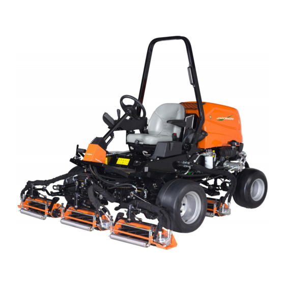
Super Light Fairway Mower
68021-F513 – SLF530, Kubota
68021-G515 – SLF530, Kubota
WARNING
Warning: If incorrectly used, this machine can
cause severe injury. Those who use and maintain
this machine should be trained in its proper use,
warned of its dangers, and must read the entire
manual before attempting to set up, operate, adjust,
or service the machine.
GB
®
D1105-E4B, 3WD,
®
D1105-E4B, 4WD,
676404-Rev A
Smooth Tires
Smooth Tires
When Performance Matters.
™
Advertisement
Table of Contents

Related Manuals for Jacobsen SLF530


Summary of Contents for Jacobsen SLF530
- Page 1 676404-Rev A Safety, Operation, & Maintenance Manual Super Light Fairway Mower Smooth Tires ® 68021-F513 – SLF530, Kubota D1105-E4B, 3WD, Smooth Tires ® 68021-G515 – SLF530, Kubota D1105-E4B, 4WD, WARNING Warning: If incorrectly used, this machine can cause severe injury. Those who use and maintain...
-
Page 2: Table Of Contents
TABLE OF CONTENTS Introduction 8.1 Maintenance And Lubrication Charts........54 8.2 General Precautions ............57 1.1 Important ................2 8.3 Engine................57 1.2 Product Identification............3 8.4 Engine Lubrication ............58 1.3 Key Numbers ..............3 8.5 Engine Coolant ..............59 1.4 parts manual ...............3 8.6 Hydraulic System ..............61 1.5 Guidelines For The Disposal Of Scrap Products ....4 8.7 Hydraulic Filter ..............62 Safety... -
Page 3: Introduction 1
1Introduction IMPORTANT ______________________________________________________________ The SLF530 with a Diesel engine is a self propelled reel mower. With hydraulic systems to power the traction drive, the cutting unit lift and lower, the cutting unit drives and the steering. IMPORTANT: Do the maintenance indicated in this manual to make sure that the quality of cut is kept at a high level. -
Page 4: Product Identification
Website – www.jacobsen.com. Select the “ONLINE PARTS LOOK-UP” tab. These pages will show the parts list and the line drawings you need to help with the identification of spare parts. Website – www.jacobsen.com. Select the “MANUALS” tab. You have the option to view or “Download” a PDF version of the parts manual. -
Page 5: Guidelines For The Disposal Of Scrap Products
Some parts are not easily separated e.g. Hydraulic hoses. These materials must be added to the “General discarded materials” area. • Do not burn discarded materials. Change the machinery records to show that the machine is not in operation and is discarded. Supply this serial number to The Jacobsen Warranty Department to close their records. en-4... -
Page 6: Safety
Manuals in additional languages may be available on the Jacobsen or RansomesJacobsen website. Read all of the instructions for this mower carefully. Know the controls and the correct operation of the equipment. - Page 7 SAFETY 2 Inspect the cutting system before you start the mower. Make sure the blades are free to rotate. When you rotate one blade, other blades can rotate. 2.1.3 OPERATION Never operate the engine without enough ventilation or in an enclosed area. The carbon monoxide in the exhaust fumes can increase to dangerous levels.
-
Page 8: Maintenance And Storage
ROPS. Do not remove the ROPS from the mower. Jacobsen must approve any changes to the ROPS. 2.1.5 SAFE HANDLING OF FUELS The fuel and the fuel vapors are flammable. Use caution when you add the fuel to the mower. The fuel vapors can cause an explosion. - Page 9 Keep all nuts, bolts and screws tight to make sure the equipment is in safe condition. Replace worn or damaged parts for safety. Replace damaged or worn labels. Only use parts, accessories and attachments approved by Jacobsen. To decrease the fire hazard, remove materials that burn from the engine, muffler, battery tray and fuel tank area.
-
Page 10: Important Safety Notes
2 SAFETY 2.1.8 IMPORTANT SAFETY NOTES _______________________________________________ This safety alert symbol gives a warning of possible hazards. DANGER - Indicates a dangerous condition that WILL cause death or injury unless it is prevented. WARNING - Indicates a dangerous condition that CAN cause death or injury unless it is prevented. CAUTION - Indicates a dangerous condition that can cause injury and property damage unless it is prevented. - Page 11 2006/42/EC Sections 3.2.2, Seating & 3.4.3, Rollover. (ANSI B71.4-2012 section 20.7) Jacobsen recommends that the owner/user of the machine completes a local risk assessment of the machine to find any conditions that do not follow this rule. e.g. when you drive the machine next to water or on the highway.
- Page 12 2 SAFETY WARNING Vibration Exposure Limits Exposure limits are calculated as a combination of the vibration level (magnitude) of the tool and the Daily Exposure Time (Trigger Time). E.g. A product with 5m/s² vibration can be used up to 2 hours/day to reach the EAV and up to 8 hours/day to reach the ELV.
-
Page 13: Labels 3
LABELS 3 3Labels SAFETY LABELS __________________________________________________________ 20°+ 4262591 009034880 S ≤ 15 mg/kg 4324674 4181865 REV B 009034920 Caution, Stay Away From Hot Surfaces. 009034880 Caution, Fan blade, do not open or remove the safety shields while the engine is in operation. 009034900 Caution, Drive belt, do not remove the safety shields while the engine is in operation. -
Page 14: Instruction Labels
3 LABELS INSTRUCTION LABELS 1.37 - 1.72 bar 20 - 25 psi 4397486 3008682 Description 009034770 Guaranteed Sound Power Level 4397046 Jacking Point 4323911 Tire Pressure 4164580 Lubrication Point 4397486 Traction Pedal 3008682 Tow Valve 838363 Throttle en-13... -
Page 15: Controls 4
CONTROLS 4 4Controls OPERATOR COMPARTMENT ________________________________________________ 4.2 - Control Panel 4.3 - Throttle Control 4.4 - Armrest Adjuster 4.5 - Traction Pedal 4.6 - Mow Speed Lever 4.7 - Steering Tilt Lever 4.8 - Brake Valve (Under Floorboard) 4.9 - Tow Valve en-14... -
Page 16: Control Panel
4 CONTROLS CONTROL PANEL _________________________________________________________ 4.2.6 4.2.3 4.2.5 4.2.1 4.2.2 4.2.4 4.2.1 - Key Switch 4.2.2 - Parking Brake Switch 4.2.3 - Mow Switch 4.2.4 - Light Switch (Optional) 4.2.5 - Lift/Lower Joystick 4.2.6 - Visual Display en-15... -
Page 17: Key Switch
CONTROLS 4 4.2.1 KEY SWITCH _____________________________________________________________ Turn the key switch to the 'START' position to start the engine. When the engine starts, release the key and allow to return automatically to the 'RUN' position.’ To stop the engine, turn the key to the ‘OFF’ position. NOTE. - Page 18 4 CONTROLS 4.2.5 LIFT/LOWER JOYSTICK ____________________________________________________ The lift/lower joystick controls the cutting units lift and lower. The lift/lower joystick operates in One-Touch or manual mode. Push the lift/lower joystick to lower the cutting units or pull the lift/lower joystick to lift the cutting units. The One-Touch or manual mode is set on the display.
- Page 19 CONTROLS 4 4.2.6.2 WARNING / SERVICE SCREEN _____________________________________________ After the startup screen the warning screen is shown. The warning screen is visible for three seconds. If there is no input needed, the main screen will become visible. If a fault condition has occurred during the previous start, pop up screen will become visible over the top of the warning screen.
- Page 20 4 CONTROLS 4.2.6.4 ENGINE START __________________________________________________________ When the key switch is turned to the start position and the interlocks are set, this screen is shown. To start the engine, the parking brake switch must be in the ON position, the mow switch must be in the OFF position and the foot pedal must be in the Neutral position.
- Page 21 CONTROLS 4 4.2.6.7 MAIN MENU _____________________________________________________________ When the first screen is shown on the display, press the LEFT or RIGHT arrow keys to access the main menu. M a i n M e n u L a n g u a g e C l o c k D i s p l a y S e t t i n g s Ve h i c l e S e t t i n g s...
- Page 22 4 CONTROLS 4.2.6.9 LANGUAGE _____________________________________________________________ Press the LEFT or RIGHT arrow keys to display the main menu. M a i n M e n u L a n g u a g e C l o c k Use the UP and DOWN arrow keys until the green arrow D i s p l a y S e t t i n g s...
- Page 23 CONTROLS 4 4.2.6.11 DISPLAY SETTINGS _____________________________________________________ Press the LEFT or RIGHT arrow keys to display the main menu. M a i n M e n u L a n g u a g e Use the UP and DOWN arrow keys until the green arrow C l o c k D i s p l a y S e t t i n g s Ve h i c l e S e t t i n g s...
- Page 24 4 CONTROLS 4.2.6.13 MEASURE UNITS _______________________________________________________ Navigate to the Vehicle Settings Menu. M e a s u r e U n i t s S e t t i n g s Ve h i c l e S e t t i n g s M e n u Use the UP and DOWN Te m p e r a t u r e...
- Page 25 CONTROLS 4 4.2.6.15 SERVICE MENU _________________________________________________________ Press the LEFT or RIGHT arrow keys to display the main menu. M a i n M e n u L a n g u a g e C l o c k Use the UP and DOWN arrow keys until the green arrow is D i s p l a y S e t t i n g s...
- Page 26 4 CONTROLS 4.2.6.16 FAULT LOG ____________________________________________________________ Navigate to the Service Menu. S e rv i c e M en u Use the UP and DOWN arrow keys until the green arrow Fau l t L og Ti m e U n t i l S e r v i c e next to Fault Log.
- Page 27 CONTROLS 4 4.2.6.17 TIME UNTIL SERVICE ____________________________________________________ Navigate to the Service Menu. S e r v i c e M e n u Use the UP and DOWN arrow keys until the green arrow F aul t Log Ti m e U n t i l S e r v i c e next to Time Until Service.
- Page 28 4 CONTROLS 4.2.6.19 I/O DIAGNOSTICS _______________________________________________________ Start the engine. Navigate to the Service Menu. S e rv i c e M en u Use the UP and DOWN arrow keys until the green arrow Fau l t L og Ti m e U n t i l S e r v i c e next to I/O Diagnostics.
- Page 29 CONTROLS 4 4.2.6.21 CONNECTOR J2 ________________________________________________________ This screen shows the status of the J2 connector circuits. Connector J2 Press the left side button to return to I/O diagnostics menu. J2-1 Lower Solenoid J2-2 J2-3 Lift Solenoid J2-4 Fan On J2-5 Park Brake Solenoid Values are shown for illustration purposes only.
- Page 30 4 CONTROLS 4.2.6.24 CONNECTOR J5 ________________________________________________________ This screen shows the status of the J5 connector circuits. Connector J5 Press the left side button to return to I/O diagnostics menu. J5-1 J5-2 Mow Solenoid J5-3 J5-4 Mow Solenoid 2 J5-5 Side Shift Right Solenoid Values are shown for illustration purposes only.
- Page 31 CONTROLS 4 4.2.6.27 ONE TOUCH____________________________________________________________ Navigate to the PIN Menu. See 4.2.6.14 P IN Men u Use the UP and DOWN arrow keys until the green arrow O n e To u c h C h a n g e P I N next to One Touch.
- Page 32 4 CONTROLS 4.2.6.29 SET DEFAULT PARAMETERS_____________________________________________ Navigate to the PIN Menu. See 4.2.6.14 P I N Me nu Use the UP and DOWN arrow keys until the green arrow O n e To u c h C h a n g e P I N next to Set Default Parameters.
- Page 33 CONTROLS 4 WARNINGS NOTICE The number in the top right of the screen indicates the total number of current faults recorded. If more than one fault, it will cycle all current faults. 4.2.6.31 WARNING OIL-PRESSURE FAULT _________________________________________ When this screen is shown, the engine oil pressure has decreased below the normal level.
- Page 34 4 CONTROLS 4.2.6.34 WARNING RELEASE BRAKE _____________________________________________ When this screen is shown, the traction pedal was pressed with the parking brake engaged. Disengage the parking brake before the traction pedal is pressed. 4.2.6.35 WARNING BATTERY FAULT ______________________________________________ When this screen is shown, the battery is below 10.5V for 30 seconds. 4.2.6.36 WARNING SERVICE NEEDED _____________________________________________ When this screen is shown, scheduled maintenance is required.
-
Page 35: Throttle Lever
CONTROLS 4 4.2.6.37 WARNING CONTROLLER I/O FAULT _______________________________________ When this screen is shown, there is a controller I/O fault. Go to I/O Diagnostics for solenoid identification. See Section 4.2.6.19 Glow Relay Fault (J5-8) Start Relay Fault (J1-6) Fuel Hold Fault (J2-6) Fuel Pull Fault (J6-1)... -
Page 36: Traction Pedal
4 CONTROLS TRACTION PEDAL ________________________________________________________ The traction pedal is found on the right side of the footplate. • Carefully press the top (A) of the foot pedal to reach the forward speed that you need. • To stop - Carefully return the foot pedal to the Neutral position. -
Page 37: Parking Brake Release Valve
CONTROLS 4 PARKING BRAKE RELEASE VALVE __________________________________________ The Parking Brake Release Valve is situated under the operator platform, on the left hand side of chassis plate. The Parking Brake Release Valve is used to release the parking brake when the engine is not in operation. The Parking brake is released with the hand wheel (A) turned completely to the right (clockwise), after you release lock wheel (B). -
Page 38: Operation
5 OPERATION 5Operation DAILY INSPECTION _______________________________________________________ CAUTION The inspection must be done each day when the engine is turned off and all fluids are cold. Lower the cutting units to the ground, engage the parking brake, stop the engine and remove the ignition key. Do a visual inspection of the mower. -
Page 39: Interlock System
OPERATION 5 INTERLOCK SYSTEM ______________________________________________________ The Interlock System prevents the engine from starting unless the parking brake switch is in the ON position, the traction pedal is in the NEUTRAL position and the mow switch is in the OFF position. The system stops the engine if the operator leaves the seat with the mow switch in the ON position, traction pedal out of the NEUTRAL position or the parking brake switch in the OFF position. -
Page 40: Operating Procedure
5 OPERATION OPERATING PROCEDURE __________________________________________________ WARNING This mower has a Roll Over Protection Structure (ROPS). Always wear the seat belt with the ROPS. If the mower is over turning, hold the steering wheel. Do not try to move off the mower or leave the seat. CAUTION To prevent injury, always wear the safety glasses, leather work shoes or boots, a hard hat and ear protection. -
Page 41: Starting The Engine
OPERATION 5 STARTING THE ENGINE ____________________________________________________ Start the engine with the operator in the seat, the mow switch (A) in the OFF position and the parking brake switch (B) in the ON position. Remove your foot from the traction pedal. Always wear the seat belt. Set the throttle lever to half throttle. -
Page 42: Driving
5 OPERATION DRIVING _________________________________________________________________ Read and follow all safety instructions contained in this manual when you drive the mower. When you operate in the reverse direction, look behind you to make sure you have a clear path. IMPORTANT: Equipment must meet the current regulations to be driven on the public roads. Push the mow switch to the OFF position and lift the cutting units to the transport position. -
Page 43: Mowing On Slopes
OPERATION 5 MOWING ON SLOPES ______________________________________________________ The mower is made to have good traction and to have good balance. Operate the mower with caution when you drive on a gradient. If you drive on wet grass, the traction and steering control of the mower are decreased. - Page 44 5 OPERATION How to calculate a slope: Tools Required: Level (A), either 1 yard, or 1 meter long. Tape measure (B). Use the level (A) and position it horizontally to measure the distance (C) with tape measure (B). Use the chart to calculate the slope angle or the percentage grade of the slope (D).
-
Page 45: Towing The Mower
NOTICE When you tow the mower, do not drive more than 2 mph (3.2 km/hr). Jacobsen recommends that you do not tow the mower for long distances. When the mower gets to the service area, close the tow valve completely and set the brake valve for normal operation. -
Page 46: To Remove A Blockage From Cutting Units
5 OPERATION 5.11 TO REMOVE A BLOCKAGE FROM CUTTING UNITS _____________________________ Stop and lift the cutter units before you move the machine to level ground. Turn off the engine and remove the ignition key. Wear the personal protective equipment that is applicable for this work, for example eye protection, gloves and correct footwear. -
Page 47: Adjustments 7
Always use the jack stands. A qualified technician must always make the adjustments and do the maintenance. If the correct adjustments can not be made, contact your Jacobsen Dealer. Inspect the equipment according to the maintenance schedule and keep complete records. -
Page 48: Steering Shaft Adjustment
7 ADJUSTMENTS STEERING SHAFT ADJUSTMENT ____________________________________________ The rear axle must be adjusted for 1/16 inch (1.6 mm) toe-in. Turn the rear wheels to the straight position. Loosen the jam nuts (B) on both ends of the tie rod (A). Rotate the tie rod (A) to get the correct toe-in (C). the Toe-in must not be more than +1/16 inch (+ 1.6 mm). -
Page 49: Traction Pedal Stops
ADJUSTMENTS 7 TRACTION PEDAL STOPS __________________________________________________ The traction pedal has three pedal stops to limit the speed of the mower. The forward transport speed stop (A) is used to set the maximum transport speed. Make sure the mow speed lever (C) is in the transport position. -
Page 50: Bedknife-To-Reel
7 ADJUSTMENTS BEDKNIFE-TO-REEL _______________________________________________________ Check the reel bearings for end play or radial play. Inspect the reel blades and the bedknife to make sure of good sharp edges without bends or surface 1/16 in. damage. Bedknife (0.15 cm) The leading edge of the reel blades must be sharp, without rough edges and show no indications of becoming blunt. -
Page 51: Cutting Height
ADJUSTMENTS 7 7.10 CUTTING HEIGHT _________________________________________________________ Note: Always make the reel-to-bedknife adjustment before you adjust the height of cut. See Sections 7.8 and 7.9. Lift the cutting units to the transport position. Set the parking brake switch in the ON position, stop the engine and remove the key from the ignition switch. -
Page 52: Flash Attach
7 ADJUSTMENTS 7.12 FLASH ATTACH ™ _________________________________________________________ Installing Cutting units Place each cutting unit in front of the lift arm. Raise the lift arm and place the cutting unit so that the yoke is aligned to the swivel housing. Carefully lower the lift arm on the yoke. -
Page 53: Bedknife Adjuster Spring
ADJUSTMENTS 7 7.14 BEDKNIFE ADJUSTER SPRING ______________________________________________ For correct operation, the bedknife adjuster spring must be compressed to 1-7/16 to 1-1/2 in. (3.65 to 3.8 cm). To adjust the spring compression, loosen or tighten the locknut to get 1-7/16 to 1-1/2 in. a distance of 1-7/16 to 1-1/2 in. -
Page 54: Torque Specification
Jacobsen uses Grade 5 (Inch) and Grade 8.8 (Metric) Plated bolts, unless a note is given. Always check the marks on the head of the bolts for the bolt grade. For tightening plated bolts, use the value given for lubricated. -
Page 55: Maintenance And Lubrication 8
MAINTENANCE AND LUBRICATION 8 8Maintenance and Lubrication MAINTENANCE AND LUBRICATION CHARTS __________________________________ Machine Service Interval Chart Interval Item Section First 50 hours • Change the Engine oil • Change the engine oil filter • Change the Hydraulic Filter Elements Each day •... - Page 56 8 MAINTENANCE AND LUBRICATION Fluid Requirements Quantity Type Engine Oil (with filter) 5.1 liters 1.12 Imp gals 1.35 US gals 10-30W (see specification below) Hydraulic Oil (with filter) 28.4 liters 6.2 Imp gals 7.5 US gals Total Equivis ZS46 (ISO VG 46) Radiator Coolant 7.6 liters 1.67 Imp gals...
- Page 57 MAINTENANCE AND LUBRICATION 8 4WD Option Only Reel Mower X5 en-56...
-
Page 58: General Precautions
The operation and maintenance during the first 50 hours of a new engine can make a difference to the performance and life of the engine. During the first 50 hours of operation, Jacobsen recommends the following. • Allow the engine to reach a temperature of at least 60° C (140° F) before operation at full load. -
Page 59: Engine Lubrication
MAINTENANCE AND LUBRICATION 8 ENGINE LUBRICATION _____________________________________________________ Check Engine Oil Level Check the engine oil level before you start or at least five minutes after you stop the engine. Park the machine on level ground, remove the dipstick (A), clean with a cloth and replace in position. Remove the dipstick (A) again and check the oil level. -
Page 60: Engine Coolant
Check and tighten the engine fan belt (see maintenance chart) and replace the belt (see maintenance chart). Replace the clamps and hoses (see maintenance chart). Have your Jacobsen Dealer check the cooling system if you need to add coolant more than one time a month or you add more than a liter of coolant at a time. - Page 61 MAINTENANCE AND LUBRICATION 8 Check The Engine Coolant Level The level of coolant in a cold expansion tank must be between the MIN and MAX indicators. WARNING To prevent injury from the hot-engine coolant or steam, never remove the expansion tank cap with the engine in operation.
-
Page 62: Hydraulic System
8 MAINTENANCE AND LUBRICATION HYDRAULIC SYSTEM ______________________________________________________ Drain and replace the hydraulic oil if one of the following occur. • Component failure. • Water or foam in the hydraulic fluid. • The hydraulic fluid has a rancid odor (indication of high heat). •... -
Page 63: Hydraulic Filter
MAINTENANCE AND LUBRICATION 8 HYDRAULIC FILTER _______________________________________________________ The hydraulic system is protected by one 10 micron filter. A 25 psi (1.7 BAR) visual indicator (A) is on the side of the filter head to indicate when service is needed. When you replace the filter: Fill the new filter with hydraulic fluid and lubricate the filter O-ring with hydraulic fluid before you install the new filter. -
Page 64: Hydraulic Hoses
8 MAINTENANCE AND LUBRICATION HYDRAULIC HOSES ______________________________________________________________ WARNING To prevent injury from the hot, high pressure oil, never use your hands to check for oil leaks. Use paper or cardboard to find leaks. The hydraulic fluid pressure can have enough force to enter your skin. If hydraulic fluid has entered your skin, a doctor must remove the hydraulic fluid surgically within a few hours or gangrene can occur. -
Page 65: Fuel
MAINTENANCE AND LUBRICATION 8 FUEL ____________________________________________________________________ Diesel fuel is flammable. Use caution when you add fuel to the mower. Only use an approved container. The spout on the container must fit inside the fuel filler neck. Never use the containers that are not approved to keep or transfer fuel. -
Page 66: Air Cleaner
8 MAINTENANCE AND LUBRICATION How To Bleed The Air From The Fuel System After the fuel filters are replaced or the fuel hoses are disconnected, bleed the air from the fuel system. Open the air vent at the top of the filter. Turn the ignition switch to the RUN position, but do not start the engine. -
Page 67: Battery
MAINTENANCE AND LUBRICATION 8 8.11 BATTERY ________________________________________________________________ Before you service the battery, make sure the ignition switch is in the OFF position and the key is removed. CAUTION When you service the battery, always use tools with insulation, wear protective glasses and protective clothing. -
Page 68: Charge The Battery
8 MAINTENANCE AND LUBRICATION When the cables are connected, start the engine on the vehicle with the good battery, then start the mower. 8.12 CHARGE THE BATTERY __________________________________________________________ WARNING Charge the battery in an area with good airflow. The battery can release hydrogen gas that is explosive. To prevent an explosion, keep any device that can cause sparks or flames away from the battery. -
Page 69: Wheel Mounting Procedure
This instruction is given to meet: The machinery directive, 2006/42/EC Sections 3.2.2, Seating & 3.4.3, Rollover. Jacobsen recommends that the owner/operator of the machine complete a local risk assessment on the machine to find any conditions that do not follow this rule. -
Page 70: Backlap
8 MAINTENANCE AND LUBRICATION 8.17 BACKLAP________________________________________________________________ Start the engine. Press the LEFT arrow key to display the main menu. Use the UP and DOWN arrow keys to until the green arrow is next to Backlap. M a i n M e n u L a n g u a g e C l o c k D i s p l a y S e t t i n g s... -
Page 71: Care And Cleaning
To keep the original high polish of the plastic parts, wax with a good grade one-step cleaner and wax combination product. Repair damaged metal surfaces and use Jacobsen touch-up paint. Apply wax to the equipment for maximum paint protection. CAUTION To prevent fire, clean grass clippings and dirt from the cutting units, drives, engine and exhaust components. -
Page 72: Mower Storage
8 MAINTENANCE AND LUBRICATION 8.19 MOWER STORAGE ________________________________________________________ General • Clean the mower and lubricate. Repair and paint damaged or open metal. • Inspect the mower, tighten all hardware, replace worn or damaged components. • Drain and fill the radiator. •... -
Page 73: Problem Solving 9
PROBLEM SOLVING 9 9Problem Solving ENGINE PROBLEM SOLVING ________________________________________________ The Engine is difficult to start Cause Action Check the fuel tank and fuel filter. The fuel is thick and does not flow. Remove any contamination from the fuel system. Clean the fuel filter with kerosene. The fuel system is a pressure type. - Page 74 9 PROBLEM SOLVING Dirty Smoke or carbon increase on the Exhaust Cause Action Wrong fuel Only use Diesel fuel specified in specification section. Bad Nozzle If necessary, replace the nozzle. Engine must be stopped immediately Cause Action The color of the exhaust turns dark. Check the fuel system and the fuel injection nozzle.
-
Page 75: Quality Of Cut 10
QUALITY OF CUT 10 10Quality of Cut 10.1 QUALITY OF CUT PROBLEM SOLVING________________________________________ Make a “test cut” to check the performance of the mower before you start the repairs. This area must have turf conditions that are known and do not change across the area. This type of area allows an accurate inspection of the perfomance of the mower to be made. -
Page 76: Marcelling
10 QUALITY OF CUT 10.3 MARCELLING ____________________________________________________________ Marcelling is a repeated pattern of different cutting heights, that causes an appearance that is like a wave. In most cases, the wave tip-to-tip distance is 2 in. (5 cm) or less. NOTE: Arrow indicates direction of travel. Probable Cause Remedy The cut (ground) speed is higher than normal. -
Page 77: Step Cutting
QUALITY OF CUT 10 10.4 STEP CUTTING ___________________________________________________________ Step cutting occurs when grass is cut higher on one side of a cutting unit than the other side. Step cutting can occur when one cutting unit is higher than another cutting unit. -
Page 78: Scalping
10 QUALITY OF CUT 10.5 SCALPING _______________________________________________________________ Scalping is a condition in which areas of grass are cut shorter than the adjacent areas. The area can be light green or brown. A low HOC setting or turf that is not level can cause scalping. -
Page 79: Stragglers
QUALITY OF CUT 10 10.6 STRAGGLERS ____________________________________________________________ Stragglers are separated blades of grass that are not cut, or are cut incorrectly. NOTE: Arrow indicates direction of travel. Probable Cause Remedy Edge of the cutting blade(s) are not sharp. Backlap or grind the reels. The bedknife is not adjusted correctly. -
Page 80: Streaks
10 QUALITY OF CUT 10.7 STREAKS ________________________________________________________________ A streak is a line of grass that is not cut. The cause of a streak can be a damaged reel or bedknife. NOTE: Arrow indicates direction of travel. Probable Cause Remedy The bedknife is damaged. Replace the bedknife. -
Page 81: Windrowing
QUALITY OF CUT 10 10.8 WINDROWING ____________________________________________________________ Windrowing is the deposit of clippings increased at one end of cutting unit(s) or between cutting units. Windrowing can make a line in the direction of travel. NOTE: Arrow indicates direction of travel. Probable Cause Remedy The grass is higher than the level at which the mower... -
Page 82: Rifling Or Tramlining
10 QUALITY OF CUT 10.9 RIFLING OR TRAMLINING __________________________________________________ Rifling or tramlining is a pattern of different cutting heights that gives the grass an appearance like a wave. This appearance is normally caused by heavy contact points across a reel and bedknife. NOTE: Arrow indicates direction of travel. -
Page 83: Mismatched Cutting Units
QUALITY OF CUT 10 10.10 MISMATCHED CUTTING UNITS ______________________________________________ Mismatched cutting units is a pattern of different cutting heights, that gives the grass a stepped cut appearance. This appearance is normally caused by a mismatched HOC (height-of-cut) adjustment from one cutting unit to another unit. -
Page 84: Fuses And Relays
Never bypass fuses. Fire damage may result. NOTICE For proper operation of the SLF530 mower, do not insert a fuse in the F10 location. Placing a fuse in the F10 location will select the wrong program in the mower controllers. -
Page 85: Specifications 12
SPECIFICATIONS 12 12Specifications 12.1 ENGINE SPECIFICATION ___________________________________________________ Model: D1105-E4B Type: Vertical, water-cooled, 4-cycle diesel engine Number of Cylinders Bore and Stroke 78 mm x 78.4 mm (3.07 in. x 3.09 in.) Total Displacement 1.123 liters (68.53 cu.in.) Combustion Type Indirect Injection SAE Net Intermittent kW / rpm 18.5 kW @ 3000 rpm H.P. -
Page 86: Dimensions & Weights
68 in. Uncut Turning Circle 4WD Option 89 cm 35 in. Weight Of SLF530 Machine With ROPS, 3WD Option No Reels And Fuel 867 kg 1912 lb. Tank Empty Weight Of SLF530 Machine With ROPS, 4WD Option No Reels And Fuel 931 kg 2052 lb. - Page 87 SPECIFICATIONS 12 3WD Option Cutting Units Lowered 3WD Option Cutting Units Lowered Front View Right Side View 4WD Option Cutting Units Lifted 4WD Option Cutting Units Lifted Front View Right Side View en-86...
-
Page 88: Machine Specification
12.3 MACHINE SPECIFICATION__________________________________________________ Frame construction: Heavy duty steel chassis with formed steel frame rails. Cutting Unit Drive: SLF530, Five individual hydraulic motors. 3WD Transmission: Hydrostatic closed loop parallel series system. Variable displacement piston pump. Front high torque fixed displacement piston wheel motors. Full time auto 3WD forward. 2WD in reverse. -
Page 89: Vibration
Referenced to Hand/Arm: BS EN ISO20643:2008 Information Supplied for Physical Agents Directive 2002/44/EC By reference to: Hand/Arm Standards: BS EN ISO 5349-1 (2001) BS EN ISO 5349-2 (2002) SLF530 Hand / Arm Acceleration Maximum Accelerations m/s² Level 1.3 ± 0.4 Whole-body vibration measurement was carried out with the machine traveling in a straight line at a speed close to 6 km/h on a flat horizontal level surface. -
Page 90: Noise
12 SPECIFICATIONS 12.6 NOISE ___________________________________________________________________ When the machine was tested for sound pressure (Operator Ear). The Machinery Safety Directive 2006/42/EC And Exposure Of Workers To The Risks Arising From Physical Agents (Noise) Directive 2003/10/EC By compliance to: The Lawnmower Standard BS EN ISO 5395:2013 And... -
Page 91: Recommended Lubricants
SPECIFICATIONS 12 12.10 RECOMMENDED LUBRICANTS ______________________________________________ Grease: For rear axle: K NATE (RJL No. 4213860), or equivalent to MIL-G-23549C, MIL-G-2345C, DIN 51 825, DIN 51 818 All other applications: Shell Darina R2 lithium based grease or equivalent. 12.11 ACCESSORIES____________________________________________________________ Reels: 8 Blade 18 inch Left Hand Reel (Right Front and Right Rear Positions) Kit number 62298... - Page 92 13 NOTES 13Notes en-91...
- Page 93 NOTES 13 en-92...
- Page 94 Equipment from Jacobsen is built to exacting standards ensured by ISO 9001 and ISO 14001 registration at all of our manufacturing locations. A worldwide dealer network and factory trained technicians backed by Genuine Jacobsen Parts provide reliable, high-quality product support.
Need help?
Do you have a question about the SLF530 and is the answer not in the manual?
Questions and answers