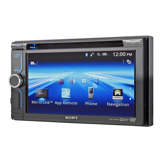
Sony XAV-602BT Service Manual
Hide thumbs
Also See for XAV-602BT:
- Operating instructions manual (145 pages) ,
- Owner's record (65 pages) ,
- Operating instructions manual (164 pages)
Table of Contents
Advertisement
SERVICE MANUAL
Ver. 1.0 2013.09
The service manual of the mechanism
deck, used in this model, has been issued
in a separate volume. Please refer to the
service manual of the MG-614 series for
the mechanism deck information.
FOR UNITED STATES CUSTOMERS. NOT
APPLICABLE IN CANADA, INCLUDINGIN THE
PROVINCE OF QUEBEC.
POUR LES CONSOMMATEURS AUX ÉTATS-
UNIS. NON APPLICABLE AU CANADA, Y
COMPRIS LA PROVINCE DE QUÉBEC.
AUDIO POWER SPECIFICATIONS
(US and Canadian models only)
CEA2006 Standard
Power Output: 17 Watts RMS
4 at
4 Ohms < 1% THD+N
SN Ratio: 80 dBA
(reference: 1 Watt into 4 Ohms)
Monitor section
Display type: Wide LCD color monitor
Dimensions: 6.1 in
System: TFT active matrix
Number of pixels:
1,152,000 pixels (800
3 (RGB)
480)
Color system:
PAL/NTSC/SECAM/PAL-M/PAL-N automatic
select
Tuner section
(US and Canadian models)
FM
Tuning range: 87.5 – 107.9 MHz
Antenna (aerial) terminal:
External antenna (aerial) connector
Intermediate frequency: 25 kHz
Usable sensitivity: 9 dBf
Selectivity: 75 dB at 400 kHz
Signal-to-noise ratio: 80 dB (mono)
Separation at 1 kHz: 50 dB
Frequency response: 20 – 15,000 Hz
AM
Tuning range: 530 – 1,710 kHz
Antenna (aerial) terminal:
External antenna (aerial) connector
Intermediate frequency:
9,115 kHz or 9,125 kHz/5 kHz
Sensitivity: 26 μV
Tuner section (AEP and UK models)
FM
Tuning range: 87.5 – 108.0 MHz
Antenna (aerial) terminal:
External antenna (aerial) connector
Intermediate frequency: 25 kHz
Usable sensitivity: 9 dBf
Selectivity: 75 dB at 400 kHz
Signal-to-noise ratio (stereo): 80 dB (mono)
Separation at 1 kHz: 50 dB
Frequency response: 20 – 15,000 Hz
MW/LW
Tuning range:
MW: 531 – 1,602 kHz
LW: 153 – 279 kHz
Antenna (aerial) terminal:
External antenna (aerial) connector
Intermediate frequency:
9,124.5kHz or 9,115.5kHz/4.5kHz
Sensitivity: MW: 26 μV, LW: 46 μV
9-893-836-01
Sony Corporation
2013I33-1
©
2013.09
Published by Sony Techno Create Corporation
Model Name Using Similar Mechanism
Mechanism Type
Optical Pick-up Name
SPECIFICATIONS
Tuner section (Russian model)
DVD/CD Player section
Signal-to-noise ratio: 120 dB
FM
Frequency response: 10 – 20,000 Hz
Tuning range:
Wow and flutter: Below measurable limit
FM1/FM2: 87.5 - 108.0 MHz (at 50 kHz step)
Harmonic distortion: 0.01%
FM3: 65 - 74 MHz (at 30 kHz step)
Region code: Labeled on the bottom of the unit
Antenna (aerial) terminal:
External antenna (aerial) connector
USB Player section
Intermediate frequency: 25 kHz
Interface: USB (High-speed)
Usable sensitivity: 9 dBf
Maximum current: 1 A
Selectivity: 75 dB at 400 kHz
Signal-to-noise ratio (stereo): 80 dB (mono)
Separation at 1 kHz: 50 dB
Wireless Communication
Frequency response: 20 - 15,000 Hz
MW/LW
Communication System:
Tuning range:
Output:
MW: 531 – 1,602 kHz
LW: 153 – 279 kHz
Maximum communication range:
Antenna (aerial) terminal:
External antenna (aerial) connector
Frequency band:
Intermediate frequency:
9,124.5 kHz or 9,115.5 kHz/4.5 kHz
Modulation method: FHSS
Sensitivity: MW: 26 μV, LW: 46 μV
Compatible Bluetooth Profiles*
Tuner section (E (NTSC) model)
FM
Tuning range:
87.5 – 108.0 MHz (at 100 kHz step)
87.5 – 107.9 MHz (at 200 kHz step)
Maximum number of storable phonebook
FM tuning step: 100 kHz/200 kHz switchable
Antenna (aerial) terminal:
External antenna (aerial) connector
*1 The actual range will vary depending on factors such
Intermediate frequency: 25 kHz
Usable sensitivity: 9 dBf
Selectivity: 75 dB at 400 kHz
Signal-to-noise ratio (stereo): 80 dB (mono)
Separation: 50 dB at 1 kHz
*2 Bluetooth standard profiles indicate the purpose
Frequency response: 20 – 15,000 Hz
AM
Tuning range: 530 – 1,710 kHz
Power amplifier section
Antenna (aerial) terminal:
Outputs: Speaker outputs
External antenna (aerial) connector
Speaker impedance: 4 – 8 ohms
Intermediate frequency:
Maximum power output: 52 W
9,124.5 kHz or 9,115.5 kHz/4.5 kHz
Sensitivity: 26 μV
General
Tuner section
Outputs:
(E (PAL) and Indian models)
FM
Tuning range: 87.5 – 108.0 MHz
Antenna (aerial) terminal:
External antenna (aerial) connector
Intermediate frequency: 25 kHz
Usable sensitivity: 9 dBf
Selectivity: 75 dB at 400 kHz
Signal-to-noise ratio (stereo): 80 dB (mono)
Separation at 1 kHz: 50 dB
Frequency response: 20 – 15,000 Hz
AM
Tuning range: 531 – 1,602 kHz
Antenna (aerial) terminal:
External antenna (aerial) connector
Intermediate frequency:
9,124.5 kHz or 9,115.5 kHz/4.5 kHz
Sensitivity: 26 μV
XAV-602BT
1.5 A (HIGH CHARGE mode)
Bluetooth Standard version 2.1 + EDR
Bluetooth Standard Power Class 2 (Max. +4 dBm)
Line of sight approx. 10 m (33 ft)*
1
2.4 GHz band (2.4000 – 2.4835 GHz)
2
:
A2DP (Advanced Audio Distribution Profile) 1.2
AVRCP (Audio Video Remote Control Profile) 1.3
HFP (Handsfree Profile) 1.5
PBAP (Phone Book Access Profile)
OPP (Object Push Profile)
SPP (Serial Port Profile)
contacts:
1,000
as obstacles between devices, magnetic fields
around a microwave oven, static electricity,
reception sensitivity, antenna's performance,
operating system, software application, etc.
of Bluetooth communication between devices.
4 (at 4 ohms)
Video output terminal (rear)
Audio output terminals (front/rear)
Audio output terminal (Z×Z)
Subwoofer output terminal
Power antenna (aerial)/Power amplifier control
terminal (REM OUT) (US, Canadian, E (NTSC),
E (PAL) and Indian models only)
Power antenna (aerial) relay control terminal
(AEP, Russian and UK models only)
Power amplifier control terminal
(AEP, Russian and UK models only)
US Model
Canadian Model
AEP Model
UK Model
E Model
XAV-601BT
MG-614D-189
TOP1300SE C11
Inputs:
Illumination control terminal
SiriusXM input terminal
(US and Canadian models only)
Remote controller input terminal
Antenna (aerial) input terminal
Parking break control terminal
Microphone input terminal
Reverse input terminal
AUX audio input terminals
AUX video input terminals
USB port
Power requirements: 12 V DC car battery
(negative ground (earth))
Dimensions: Approx. 178 mm
100 mm
173 mm
1
7
(7
/
4 6
/
in) (w/h/d)
8
8
Mounting dimensions:
Approx. 182 mm
111 mm 160 mm
1
3
3
(7
/
4
/
6
/
in) (w/h/d)
4
8
8
Mass: Approx. 2.0 kg (4 lb 7 oz)
Package contents:
Parts for installation and connections (1 set)
Microphone (1)
Remote Commander (1): RM-X271
Panel Case (1)
Design and specifications are subject to change
without notice.
Region code
The region system is used to protect software
copyrights.
The region code is located on the bottom of the unit,
and only DVDs labeled with an identical region code
can be played on this unit.
DVDs labeled
can also be played.
ALL
If you try to play any other DVD, the message [Disc
playback prohibited by region code.] will appear on
the monitor screen. Depending on the DVD, no
region code may be labeled even though playing
the DVD is prohibited by area restrictions.
AV CENTER
Advertisement
Table of Contents

Related Manuals for Sony XAV-602BT


Summary of Contents for Sony XAV-602BT
-
Page 1: Service Manual
Antenna (aerial) terminal: 9,124.5 kHz or 9,115.5 kHz/4.5 kHz External antenna (aerial) connector Sensitivity: 26 μV Intermediate frequency: 9,124.5kHz or 9,115.5kHz/4.5kHz Sensitivity: MW: 26 μV, LW: 46 μV 9-893-836-01 Sony Corporation 2013I33-1 © 2013.09 Published by Sony Techno Create Corporation... - Page 2 Do not touch the soldering iron on the same conductor of the TIONNEMENT. NE REMPLACER CES COMPOSANTS QUE circuit board (within 3 times). PAR DES PIÈCES SONY DONT LES NUMÉROS SONT DON- • Be careful not to apply force on the conductor when soldering NÉS DANS CE MANUEL OU DANS LES SUPPLÉMENTS...
-
Page 3: Table Of Contents
XAV-602BT TABLE OF CONTENTS SERVICING NOTES 5-3. Printed Wiring Boards - MAIN Section (1/2) - ....34 ..........5-4. Printed Wiring Board - MAIN Section (2/2) - ....35 5-5. Schematic Diagram - MAIN Section (1/4) - ....36 GENERAL .............. -
Page 4: Servicing Notes
It is best to use only unleaded solder but unleaded solder may also be added to ordinary solder. Region Code IMPORTANT NOTE FOR REPAIRING XAV-602BT contain individual information that the customer reg- istered because it installs the Bluetooth function. When repairing, the data that the customer registered might disap- Part No. - Page 5 XAV-602BT NOTE THE MAIN BOARD OR SYSTEM CONTROLLER Note: The ten key cannot be used. (IC502) REPLACING 1. Press the [ ] or [ ] button, and select the alphanumeric char- When the complete MAIN board or system controller (IC502) is acter of “0 to F”.
- Page 6 XAV-602BT NOTE FOR FLEXIBLE BOARD OF THE OPTICAL REPLACING THE LITHIUM BATTERY OF THE REMOTE COMMANDER PICK-UP Under normal conditions, the battery will last When connecting or disconnecting the fl exible board of the opti- approximately 1 year. (The service life may be cal pick-up to or from the CN2 of the SERVO board, follow the shorter, depending on the conditions of use.)
-
Page 7: General
XAV-602BT SECTION 2 This section is extracted GENERAL from instruction manual. (US and Canadian models) English Franç ais Español Equipment used in illustrations (not supplied) / Appar eils utilisés dans les illustrations (non fournis) / Equipo utilizado en las ilustraciones (no suministrado) Cautions Précautions... - Page 8 OFF until the display disappears each time you automóviles japoneses sin el soporte suministr ado. En turn the ignition off. caso de que no pudier a, consulte al distribuidor Sony Avertissement si le contact de Parts supplied with your car más cercano.
- Page 9 XAV-602BT (AEP and UK models) English Italiano Equipment used in illustrations (not supplied) / Equipo utilizado en las ilustr aciones (no suministrado) / Appar ecchiatura utilizzata nelle illustr azioni (non in dotazione) Cautions Attenzione Run all ground (earth) leads to a common gr ound Portare tutti i cavi di massa a un punto di mas sa (earth) point.
- Page 10 In tal Amarillo Fuente de alimentación continua Rojo Fuente de alimentación conmutada algún fallo de funcionamiento interno. En tal caso, caso, rivolgersi al più vicino rivenditor e Sony. Giallo Alimentazione continua Rosso Alimentazione commutata consulte con el distribuidor Sony más cercano.
- Page 11 XAV-602BT (Russian model) Русский Українська Оборудование, фигурирующее на иллюстрациях (не прилаг ается) / Обладнання, зображене на ілюстраціях (не вх одить до комплекту пос тачання) Внимание Увага! Подведите все провода заземления к одной Підключіть усі проводи заземлення до однієї точке заземления.
- Page 12 Вибір кута кріплення Виберіть кут кріплення менше 45°. Допустимый угол установки Установите устройство под углом не бо лее 45°. Про ілюстрації XAV-602BT — це модель, що вик ористовується для Иллюстрации ілюстрацій, якщо не вказано інше. Зажим Если не указано иное, модель XAV-602BT (не...
- Page 13 XAV-602BT (E (NTSC) model) English Español Equipment used in illustrations (not supplied) / Equipo utilizado en las ilustr aciones (no suministrado) Cautions Precauciones Run all ground (earth) leads to a common gr ound Conecte todos los cables de conexión a masa a un (earth) point.
- Page 14 Acerca de las ilustraciones Connecting the parking brake XAV-602BT es el modelo que se utiliza par a las lead ilustraciones, a menos que se indique lo c ontrario. Be sure to connect the parking brake lead (light green) Conexión del cable del freno de...
- Page 15 XAV-602BT (E (PAL) and Indian models) English Equipment used in illustrations (not supplied) Cautions Run all ground (earth) leads to a common gr ound (earth) point. Front speaker Rear speaker Rear view camera This unit is designed for negative ground (earth) 12 V DC operation only.
- Page 16 Adjust the mounting angle to less than 45°. Installing on the sun visor About illustrations Installing on the dashboard XAV-602BT is the model used f or illustration purposes, unless otherwise noted. Connecting the parking brake lead Be sure to connect the parking brake lead (light green)
-
Page 17: Disassembly
XAV-602BT SECTION 3 DISASSEMBLY • This set can be disassembled in the order shown below. 3-1. DISASSEMBLY FLOW FRONT PANEL SECTION Note: Illustration of disassembly is omitted. 3-2. COVER 3-12. PANEL (BACK) BLOCK (Page 18) (Page 24) 3-3. DVD MECHANISM DECK (MG-614D-189) 3-14. -
Page 18: Cover
XAV-602BT Note: Follow the disassembly procedure in the numerical order given. 3-2. COVER 2 two claws 4 cover 1 screw (PTT2.6 2 two claws 3 three claws... -
Page 19: Dvd Mechanism Deck (Mg-614D-189)
XAV-602BT 3-3. DVD MECHANISM DECK (MG-614D-189) Note 1: The service manual of the mechanism deck, used in this model, has been issued in a separate volume. Please refer to the service manual of the MG-614 series for the mechanism deck informa- tion. -
Page 20: Bracket (Cover)
XAV-602BT 3-4. BRACKET (COVER) 1 two screws (PTT2.6 2 bracket (cover) 3-5. CONNECTOR ASSY (XM1) (US, Canadian models) 3 connector assy (XM1) – – XM cable Turn anticlockwise the XM cable once. XM board 1 connector (CN941) 2 two screws (PTT2.6... -
Page 21: Connector Assy (Nv1) (E (Pal), Indian Models)
XAV-602BT 3-6. CONNECTOR ASSY (NV1) (E (PAL), Indian models) 5 connector assy (NV1) NAVI cable – – EXT-NAVI board 3 connector (CN940) 2 connector (CN701) lead pin MAIN board 4 two screws (PTT2.6 Note: When you install the connector, please install themcorrectly. -
Page 22: Connection Cord For Automobile ( (Cnc201)
XAV-602BT 3-8. CONNECTION CORD FOR AUTOMOBILE ( ) (CNC201) tape 4 connection cord – – (sub material) guide line for automobile ( (CNC201) 2 tape (sub material) tape (sub material) 3 screw (PTT2.6 guide line 1 connector (CN202) connection cord for... -
Page 23: Dc Fan (25X25) (M801), Main Board
XAV-602BT 3-10. DC FAN (25X25) (M801), MAIN BOARD Note: When the complete MAIN board is replaced, the destination setting is necessary. Refer to “NOTE THE MAIN BOARD OR SYSTEM CONTROLLER (IC502) REPLACING” on page 5. 1 fuse (blade type) (auto fuse) -
Page 24: Sub Panel Assy
XAV-602BT 3-11. SUB PANEL ASSY Note: When you install the flexible flat cable (60 core), please install it correctly. There is a possibility that this machine damages when not correctly installing it. Insert is straight Insert is shallow Insert is incline to the interior. -
Page 25: D-Sub6 Board
XAV-602BT 3-13. D-SUB6 BOARD 1 two shafts 2 sheet (lock assy) 3 screw (B) 6 D-SUB6 board 3 screw (B) 3 screw (B) 4 Remove the solder. 5 plate (GND) – Back panel block front side view – 3-14. KEY6 BOARD... -
Page 26: Chassis (Display6) Block
XAV-602BT 3-15. CHASSIS (DISPLAY6) BLOCK Note 1: When complete DISPLAY board is exchanged, exchanged old complete DISPLAY board and is destroyed with the hammer, and throw out it. 5 claw – Front panel block rear side view – 4 flexible flat cable (10 core) -
Page 27: Display Board
XAV-602BT 3-16. DISPLAY BOARD 2 Remove the solder. 3 Bend the claw in the direction of an arrow. 6 DISPLAY board 1 three screws (T) 4, Silver) 5 shield (AP) block – Front panel block rear side view – ow to install t e s ield... -
Page 28: Liquid Crystal Display Panel (Lcd1), Touch Panel (Tpn1)
XAV-602BT 3-17. LIQUID CRYSTAL DISPLAY PANEL (LCD1), TOUCH PANEL (TPN1) settin 7 touch panel (TPN1) 5 liquid crystal display panel (LCD1) flexible flat cable sheet (LCD) guide line sheet (LCD) – Front panel block rear side view – 3 three side cussions... -
Page 29: Electrical Adjustments
XAV-602BT SECTION 4 ELECTRICAL ADJUSTMENTS 6. Press the [B] or [b] buttons on the remote commander, change MONITOR SECTION to the PAL adjustment screen. If any of the following parts was replaced, execute the “Flicker Adjustment” as mentioned below. Screen display •... - Page 30 XAV-602BT MEMO...
-
Page 31: Diagrams
XAV-602BT SECTION 5 DIAGRAMS 5-1. BLOCK DIAGRAM - AUDIO Section - J702 (1/3) LINE IC351 INPUT SELECTOR, R-CH ELECTRICAL VOLUME AMUTE IC301 MUTING Q311 POWER AMP AUDIO_FL 33 INF1 IC801 (1/2) R-CH AUDIO_FR R-CH DVD MECHANISM CN801 (1/2) DECK BLOCK... -
Page 32: Block Diagram - Video, Panel, Power Supply Section
XAV-602BT 5-2. BLOCK DIAGRAM - VIDEO, PANEL, POWER SUPPLY Section - USB CHARGING USB INTERFACE CONTROLLER IC201 M801 IC202 (FAN) SYSRSTB PSW_EN_OUT 7 +1.9V REGULATOR DISPLAY BOARD CHG_MOD1 1 X203 IC801 (2/2) D +1.9V REGULATOR 30MHz LCD1 IC101 DP_DOWN DP_UP 9... - Page 33 XAV-602BT THIS NOTE IS COMMON FOR PRINTED WIRING BOARDS AND SCHEMATIC DIAGRAMS. • Circuit Boards Location (In addition to this, the necessary note is printed in each block.) For Printed Wiring Boards. For Schematic Diagrams. Note: Note: SERVO board • All capacitors are in μF unless otherwise noted. (p: pF) 50 •...
-
Page 34: Printed Wiring Boards - Main Section (1/2)
XAV-602BT 5-3. PRINTED WIRING BOARDS - MAIN Section (1/2) - • See page 33 for Circuit Boards Location. • : Uses unleaded solder. MAIN BOARD (COMPONENT SIDE) R343 R300 R316 R344 R317 VDR309 VDR311 VDR301 C388 C818 R872 C820 VDR315... -
Page 35: Printed Wiring Board - Main Section (2/2)
XAV-602BT 5-4. PRINTED WIRING BOARD - MAIN Section (2/2) - • See page 33 for Circuit Boards Location. • : Uses unleaded solder. J702 CNC1 AUX1 CAMERA AUX1 REAR FRONT AUX2 MAIN BOARD AUDIO IN AUDIO OUT AUDIO OUT AUDIO IN... -
Page 36: Schematic Diagram - Main Section (1/4)
XAV-602BT 5-5. SCHEMATIC DIAGRAM - MAIN Section (1/4) - • See page 48 for IC Block Diagrams. M801 MAIN BOARD (1/4) CN803 (FAN) IC B/D IC801 R836 C856 C867 D829 C953 Q852 0.47 0.47 DZ2J180M0L POWER AMP, REGULATOR LSCR523UBFS8TL IC801... -
Page 37: Schematic Diagram - Main Section (2/4)
XAV-602BT 5-6. SCHEMATIC DIAGRAM - MAIN Section (2/4) - • See page 41 for Waveforms. • See page 48 for IC Block Diagrams. MAIN BOARD (2/4) MAIN BOARD (3/4) (Page 38) C105 R123 C101 0.01 C345 C346 R338 R359 C323... -
Page 38: Schematic Diagram - Main Section (3/4)
XAV-602BT 5-7. SCHEMATIC DIAGRAM - MAIN Section (3/4) - • See page 41 for Waveforms. • See page 48 for IC Block Diagrams. • See page 53 for IC Pin Function Description. MAIN BOARD (3/4) BUS4 REG+3.3V MAIN M_CVBS_GND BOARD... -
Page 39: Schematic Diagram - Main Section (4/4)
XAV-602BT • See page 41 for Waveforms. • See page 48 for IC Block Diagrams. • See page 53 for IC Pin Function Description. 5-8. SCHEMATIC DIAGRAM - MAIN Section (4/4) - MAIN BOARD (4/4) IC703 IC B/D VIDEO SELECT... -
Page 40: Printed Wiring Boards - External Terminal, Panel Section
XAV-602BT 5-9. PRINTED WIRING BOARDS - EXTERNAL TERMINAL, PANEL Section - • See page 33 for Circuit Boards Location. • : Uses unleaded solder. KEY6 BOARD KEY6 BOARD (COMPONENT SIDE) (CONDUCTOR SIDE) (US, CND) XM BOARD (Page 46) (CONDUCTOR SIDE) -
Page 41: Xm Board (Us And Canadian Models)
XAV-602BT • Waveforms 5-10. SCHEMATIC DIAGRAM - XM Board (US and Canadian models) - – MAIN Board – IC401 1 (BST) XM BOARD CN652 R663 R670 XM_Rx XM_Tx CWC2 R671 18.2 Vp-p AU_GND 2.46 s M_GND 5 V/DIV, 1 s/DIV... -
Page 42: Schematic Diagram - Ext-Navi Board (E (Pal) And Indian Models)
XAV-602BT 5-11. SCHEMATIC DIAGRAM - EXT-NAVI Board (E (PAL) and Indian models) - • See page 48 for IC Block Diagrams. EXT-NAVI BOARD C603 R627 R647 R607 R619 JL604 R622 R623 R608 R620 4.7k JL605 JL601 R609 R621 JL606 CN601... -
Page 43: Schematic Diagram - Panel Section
XAV-602BT 5-12. SCHEMATIC DIAGRAM - PANEL Section - KEY6 BOARD C2500 S2503 IC2500 ROTARY ENCODER PUSH SOURCE/ REMOTE CONTROL RECEIVER IC2500 RS-470 (VOLUME) R2507 GND1 CN2501 GND2 KEY_GND R2548 SIRCS R2500 DISP_10.4V R2512 R2515 R2518 3.3V S2500 R2505 LED_GND FFC3... -
Page 44: Printed Wiring Board - M-Sub6 Board
XAV-602BT 5-13. PRINTED WIRING BOARD - M-SUB6 Board - • See page 33 for Circuit Boards Location. • : Uses unleaded solder. D-SUB6 (Page 46) BOARD M-SUB6 BOARD M-SUB6 BOARD CN2001 (SIDE A) (SIDE B) CN2301 CN2300 (CHASSIS) C2305 C2304... -
Page 45: Schematic Diagram - M-Sub6 Board
XAV-602BT 5-14. SCHEMATIC DIAGRAM - M-SUB6 Board - M-SUB6 BOARD CN2300 VBUS_GND VBUS C2305 VBUS 100p VBUS VBUS_GND USB_D– USB_D– USB_D+ USB_D+ VBUS_GND (Page 47) +7.5V D-SUB6 BOARD +7.5V CN2001 +7.5V CN2301 +7.5V DETACH_DET USB_D– +7.5V 46 DETACH-DET USB_D– BU_IN... -
Page 46: Printed Wiring Board - D-Sub6 Board
XAV-602BT 5-15. PRINTED WIRING BOARD - D-SUB6 Board - • See page 33 for Circuit Boards Location. • : Uses unleaded solder. DISPLAY M-SUB6 BOARD (Page 40) (Page 44) BOARD CN2301 D-SUB6 BOARD D-SUB6 BOARD (SIDE A) (SIDE B) CN2001... -
Page 47: Schematic Diagram - D-Sub6 Board
XAV-602BT 5-16. SCHEMATIC DIAGRAM - D-SUB6 Board - (Page 43) D-SUB6 BOARD DISPLAY BOARD (Page 45) CN2000 M-SUB6 BOARD VBUS_GND VBUS USB_D– CN2301 USB_D– VBUS C2002 CN2001 USB_D+ 100p R2000 D2020 VDR992 USB_D+ VBUS DETACH_DET USB_D– VBUS_GND VBUS_GND 46 DETACH_DET USB_D–... - Page 48 XAV-602BT • IC Block Diagrams IC301 BD3467FV-E2 – MAIN Board – FADER FADER BOOST IC101 BD00GA5WEFJ-E2 IC102 BD7931F OUTC IC103 BD00GA3WEFJ-E2 FADER FADER A1 1 IC105 BD00GC0WEFJ-SE2 BOOST OUTS A2 2 FADER FADER B1 3 OUTR1 CONTROL BOOST LOGIC B2 4...
- Page 49 XAV-602BT IC302 NJW1240V (TE2) MUTING OUT1 IN1 1 MUTING OUT2 IN2 2 MUTING OUT3 IN3 3 MUTING OUT4 IN4 4 MUTING OUT5 IN5 5 MUTING OUT6 IN6 6 POP NOISE MUTE 7 SUPPRESSION GAIN SELECT GAIN 8 6 dB/8 dB...
- Page 50 XAV-602BT IC401, 431 OZ529IEGN-A1-0-TR BST 1 VREF OSCILLATOR LX 2 REFERENCE GENERATOR OVER CURRENT PROTECTION GNDA VIN 3 EN_SYS 4 USBOUT 5 FB_USB 6 SS_SYS ADJUSTMENT GENERATOR CHARGE EN_USB PUMP VIC_USB USBIN OVER-CURRENT ISET_USB LIMIT VOUT_SYS (USBIN) UVLS FAULT PROTECTION –...
- Page 51 XAV-602BT IC461 SI-8205NHG-TL REG_DRV ISNS GND 1 ICSPWM SS_REF ENABLE/ CURRENT EN/SS 2 ICSOCP POWER SOFT-START SENSE STANDBY STAGE VIN 3 OVER CURRENT REGULATOR PROTECT COMPARATOR REGULATOR VINOK UNDER PHASE VOLTAGE CURRENT RES_PH PHASE GATE CBCHG BS_CHG LOCK OUT LSOFF...
- Page 52 XAV-602BT IC703 NJM41050V (TE2) CLAMP VIN1 SREFV ADVANCED 12 VSAG CORRECTION CLAMP 11 SREFV VIN2 10 VCC 9 GND DRIVER 6.75MHz CLAMP LOW-PASS 8 VOUT FILTER – VIN3 MUTE IC801 TDF8556AJ/N5 – EXT-NAVI Board – IC601 BA3123F-E2 OUT1 I2C_SIO OUT2 OUT-FL–...
- Page 53 XAV-602BT • IC Pin Function Description MAIN BOARD IC201 PD720114GA-YEU-A-SAK (USB INTERFACE) Pin No. Pin Name Description VDD25OUT Internal regulator power supply voltage (+2.5V) output terminal VSSREG Ground terminal (for internal regulator) 3 to 6 LED4 to LED1 Not used...
- Page 54 XAV-602BT MAIN BOARD IC502 R5F3650KCDZ92FB (SYSTEM CONTROLLER) Pin No. Pin Name Description SPEED_IN Speed pulse signal input terminal Not used SIRCS SIRCS signal input from the panel section MHL_OVER MHL over current detection signal input terminal Not used MODEL_SEL2 Model setting terminal...
- Page 55 XAV-602BT Pin No. Pin Name Description SELF_SW Self loading position detection switch input terminal IN_SW Disc insert detection switch input terminal D_SW Chucking end detection switch input terminal MECHA_RESET Reset signal output to the DVD mechanism deck block “L”: reset...
-
Page 56: Exploded Views
XAV-602BT SECTION 6 EXPLODED VIEWS Note: • -XX and -X mean standardized parts, so • Color Indication of Appearance Parts Ex- they may have some difference from the ample: original one. KNOB, BALANCE (WHITE) . . . (RED) ... -
Page 57: Front Panel Section
XAV-602BT 6-2. FRONT PANEL SECTION LCD1 TPN1 not supplied FFC3 not supplied not supplied Note: When complete DISPLAY board is exchanged, exchanged old complete DISPLAY board and is destroyed with the hammer, and throw out it. Ref. No. Part No. -
Page 58: Sub Panel Section
XAV-602BT 6-3. SUB PANEL SECTION FPB1 Ref. No. Part No. Description Remark Ref. No. Part No. Description Remark 4-439-172-01 CUSHION (LOCK ASSY) A-1871-747-A M-SUB6 BOARD, COMPLETE 3-042-244-11 SCREW (T) 4-298-967-02 PLATE (ADJUST) 3-243-844-02 CUSHION (SUB PANEL) FPB1 1-886-726-11 PRINTED WIRING BOARD, FLEXIBLE... -
Page 59: Chassis Section
XAV-602BT 6-4. CHASSIS SECTION (E (PAL), IND) (US, CND) CWC1 CWC2 CNC202 XM board EXT-NAVI board not supplied supplied supplied (US, CND, E (PAL), IND) MAIN board section not supplied not supplied not supplied Ref. No. Part No. Description Remark Ref. -
Page 60: Main Board Section
XAV-602BT 6-5. MAIN BOARD SECTION F801 not supplied not supplied M801 CN01 MAIN board not supplied not supplied Note: When the complete MAIN board is replaced, the destination setting is necessary. Refer to “NOTE THE MAIN BOARD OR SYSTEM CONTROLLER (IC502) REPLACING” on page 5. -
Page 61: Electrical Parts List
XAV-602BT SECTION 7 DISPLAY D-SUB6 EXT-NAVI ELECTRICAL PARTS LIST Note: • Due to standardization, replacements in • CAPACITORS When indicating parts by reference num- uF: μF the parts list may be different from the ber, please include the board name. - Page 62 XAV-602BT EXT-NAVI KEY6 MAIN Ref. No. Part No. Description Remark Ref. No. Part No. Description Remark R607 1-216-864-11 SHORT CHIP R2505 1-218-990-81 SHORT CHIP R608 1-216-864-11 SHORT CHIP R2506 1-216-815-11 METAL CHIP 1/10W R2507 1-218-941-81 METAL CHIP 1/16W R609 1-216-864-11...
- Page 63 XAV-602BT MAIN Ref. No. Part No. Description Remark Ref. No. Part No. Description Remark C121 1-116-734-11 CERAMIC CHIP 1uF C343 1-165-908-11 CERAMIC CHIP 1uF C122 1-100-159-91 CERAMIC CHIP 22uF 6.3V (E (PAL), IND) C345 1-162-921-11 CERAMIC CHIP 33PF C201 1-118-347-11 CERAMIC CHIP 0.1uF...
- Page 64 XAV-602BT MAIN Ref. No. Part No. Description Remark Ref. No. Part No. Description Remark C407 1-118-347-11 CERAMIC CHIP 0.1uF C723 1-116-718-11 CERAMIC CHIP 10uF C408 1-118-345-11 CERAMIC CHIP 0.01uF C725 1-116-718-11 CERAMIC CHIP 10uF C409 1-118-459-11 CERAMIC CHIP 0.01uF C728...
- Page 65 XAV-602BT MAIN Ref. No. Part No. Description Remark Ref. No. Part No. Description Remark C867 1-116-739-11 CERAMIC CHIP 0.47uF D830 6-503-677-01 DIODE 1A4C-A2 C869 1-162-919-11 CERAMIC CHIP 22PF D831 6-503-238-01 DIODE GN1G C876 1-162-919-11 CERAMIC CHIP 22PF < FERRITE BEAD >...
- Page 66 XAV-602BT MAIN Ref. No. Part No. Description Remark Ref. No. Part No. Description Remark L101 1-481-182-21 INDUCTOR 22uH R209 1-216-864-11 SHORT CHIP L203 1-457-223-11 COMMON MODE CHOKE COIL R210 1-216-864-11 SHORT CHIP L213 1-218-990-81 SHORT CHIP R211 1-216-864-11 SHORT CHIP...
- Page 67 XAV-602BT MAIN Ref. No. Part No. Description Remark Ref. No. Part No. Description Remark R352 1-216-809-11 METAL CHIP 1/10W R506 1-218-965-11 METAL CHIP 1/16W R353 1-216-296-11 SHORT CHIP R507 1-216-845-11 METAL CHIP 100K 1/10W R356 1-218-965-11 METAL CHIP 1/16W R510...
- Page 68 XAV-602BT MAIN M-SUB6 Ref. No. Part No. Description Remark Ref. No. Part No. Description Remark R584 1-216-864-11 SHORT CHIP VDR204 1-805-043-11 ABSORBER, CHIP SURGE R585 1-216-845-11 METAL CHIP 100K 1/10W VDR301 1-804-988-21 VARISTOR, CHIP (1608) VDR302 1-804-988-21 VARISTOR, CHIP (1608)
- Page 69 XAV-602BT Ref. No. Part No. Description Remark Ref. No. Part No. Description Remark C656 1-125-972-61 ELECT 100uF M801 1-787-976-11 FAN, DC (25X25) C657 1-118-417-11 CERAMIC CHIP 0.1uF A-1971-485-A CONNECTOR ASSY (Including EXT-NAVI board) (E (PAL), IND) < CONNECTOR > 1-839-626-11...
- Page 70 XAV-602BT Ref. No. Part No. Description Remark PARTS FOR INSTALLATION AND CONNECTIONS ************************************** (AEP, RU, UK, E (NTSC), E (PAL), IND) X-2514-519-3 FRAME, FITTING ASSY (AEP, RU, UK, E (NTSC), E (PAL), IND) 3-876-675-01 KEY (FRAME) (1 piece) (AEP, RU, UK, E (NTSC), E (PAL), IND)
- Page 71 XAV-602BT MEMO...
-
Page 72: Revision History
XAV-602BT REVISION HISTORY Checking the version allows you to jump to the revised page. Also, clicking the version at the top of the revised page allows you to jump to the next revised page. Ver. Date Description of Revision 2013.09...
Need help?
Do you have a question about the XAV-602BT and is the answer not in the manual?
Questions and answers