
Related Manuals for CIGWELD 636804


Summary of Contents for CIGWELD 636804
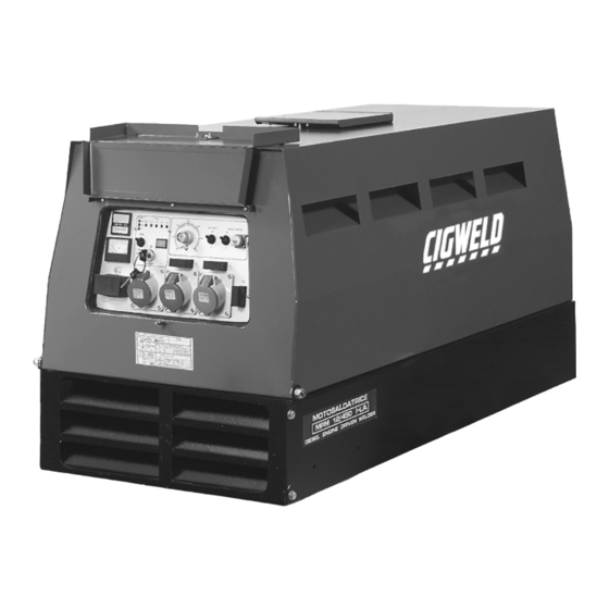
- Page 1 ENGINE DRIVEN WELDER GENERATING SET MPM 12/400 I-KA (Part Number 636804) DOC No: EDW0005 Date: 16-July-97 Issue No: 2...
-
Page 2: General Use Instructions
GENERAL USE INSTRUCTIONS Read the instructions carefully; proceed according to the regulations in use in the country where the machine will operate. TRANSPORTATION The machine must be fixed securely to the motor vehicle if it has to be moved to the place of use. -
Page 3: Service And Cleaning
RUNNING IN For the first 50 hours of operation of the machine do not employ more than 70% of the maximum power indicated in the technical specifications. STARTING AND WORKING 1- Make the earth connection (see the USE INSTRUCTIONS). 2- If the machine model IS NOT equipped with a earth leakage circuit breaker the available socket is intended ONLY for connecting the machine to a switchboard equipped with all protection devices imposed by current law regulations. -
Page 4: Specification
For service intervals consult the ENGINE USE AND SERVICE manual and the SPECIFICATION. ADJUSTMENTS AND REGULATIONS All necessary controls are located on the main control panel and are properly explained in the section FRONT PANEL DESCRIPTION. We advise the operator against tampering with the engine or the internal electrical components. -
Page 5: Technical Specification
TECHNICAL SPECIFICATION POWER PLANT INFORMATION Part number 636804 Description MPM 12/400 I-KA WELDING GENERATOR D.C. Maximum power 400A @ 36V Rated output at 60% duty cycle 350A @ 34V Range of continuous control 30A to 400A Duty cycle period 5 minutes... -
Page 6: Dimensions And Weight
ENGINE Make/Type Kubota D 1105-E Number of cylinders Displacement 1124 cc. Diesel engine output 25 HP Engine speed 3000 rpm Cooling Water Fuel tank capacity 36.5 Litres Oil capacity 5.1 Litres Starter Electric Battery 12V - 43 Ah Acoustic energy emission 97 dB(A) Acoustic pressure @ 1 metre 89 dB... -
Page 7: Engine Warranty
KUBOTA Dealer. KUBOTA guarantees an efficient technical support throughout Australia and New Zealand. Generator and equipment: Contact your local CIGWELD Distributor for spare parts. Specify the Engine Driven Welders model number, serial number and name of part (with code number) when ordering spare parts. Refer to the Spare Parts... -
Page 8: Front Panel Descriptions
FRONT PANEL DESCRIPTIONS Ignition key Arc force regulator Single phase voltmeter Basic / Cellulose switch Hourmeter Wire feeder connector 14 pin Water temperature lamp 230V single phase outlet Battery charge lamp 400V three phase outlet Oil pressure lamp 16A single phase circuit breaker Glow plug lamp ELCB (25A earth fault protection) Fuel meter... -
Page 9: Earth Fault Protection
OPERATING INSTRUCTIONS 1.1 EQUIPMENT GROUNDING CONNECTION This machine has auxiliary power capability and grounding of the frame and case is recommended. Refer to your local Supply Authority or Australian Standard AS3000 for detailed earthing instructions. Connect the earth wire to the Earth connection located on the front of the machine. -
Page 10: Starting Engine
4.1 STARTING ENGINE Check that engines fuel tank has been filled with diesel and the sump has been filled with lubricating oil as specified in the Engine Manual. Position the ignition key on the first step for preliminary heating of the glow plugs, the glow plug light illuminates. -
Page 11: Constant Current (Cc) Mode
6.1 CONSTANT CURRENT (CC) MODE Set the CC/CV mode switch to the mode CC position. If using a remote control pendant, plug remote pendant into the 14 pin remote control socket and set the REMOTE CONTROL switch to the REMOTE position. Set the REMOTE CONTROL switch to the PANEL position if a remote pendant is not used. - Page 12 8.1 USE OF ENGINE DRIVEN WELDER AS A GENERATING SET Start the engine ass described in section 4.1 Switch the ELCB lever up to setting I (ON). Switch the single phase 16A CB lever up to setting I (ON). The single phase voltmeter (see 'I' on page 7) reads approximately 170V when the engine is at idle speed.
-
Page 13: Engine Protection
Protection Device will stop the engine after approximately one minute has elapsed. 11.1 WARNING In order to preserve the engine performance CIGWELD strongly recommends that the maintenance schedule is adhered to as specified in the engine manufacturer "Use and maintenance" user manual. Poor maintenance could result in a shorter operating life, decreased performance and loss of engine warranty. - Page 14 MPM 12/400 I-KA (Part Number 636804)
- Page 15 MPM 12/400 I-KA (Part Number 636804)
- Page 16 SPARE PARTS LIST MPM 12/400 I-KA (Part Number 636804) Item Ordering Description OGS19493 Stator OGS18512 Stator protection OGS18486 Engine connection flange OGS11446 Stator tie rod OGS18699 Flange with bearing seat OGS10175 OGS18764 Fan cover OGSO905 Circlip OGS903 Bearing 100/45/25 2RS...
- Page 17 SPARE PARTS LIST MPM 12/400 I-KA (Part Number 636804) Item Ordering Denomination OGS19498 Front plate OGS10057 Plate for earth fault protection OGS839 25A earth fault protection OGS13933 Protection OGS632 16A circuit breaker OGS13191 Protection OGS19483 400V 20A three phase socket...
- Page 18 SPARE PARTS LIST MPM 12/400 I-KA (Part Number 636804) Item Ordering Denomination OGS16266 Right hand cover OGS17255 Frame OGS12786 Reactor OGS18869 Plate OGS836 Welding outlet OGS886 Plug for welding outlet OGS16940 3x60µF capacitor OGS16896 Plate for capacitor OGS16934 Plate for capacitors...
- Page 19 SPARE PARTS LIST MPM 12/400 I-KA (Part Number 636804) Item Ordering Denomination OGS16190 Battery cover OGS16191 Silencer OGS18308 Silencer extension OGS14300 Rubber puffer OGS11312 Dia. 16 rubber wire holder OGS13493 50x35 shock absorber OGS17749 Engine support OGS18302 Left engine support bracket...
- Page 20 SPARE PARTS LIST MPM 12/400 I-KA (Part Number 636804) Item Ordering Denomination OGS16280 Air grate OGS10530 Frame locking hook OGSOO90 Rubber OGS949 Jog wheel OGSO548 Adjustable clamp OGSO924 Brace OGS15247 Axle OGS10538 Wheel...
Need help?
Do you have a question about the 636804 and is the answer not in the manual?
Questions and answers