Table of Contents
Advertisement
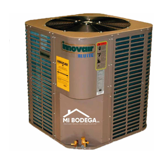
BLUTEC
INSTALLATION INSTRUCTIONS
Split System Air Conditioner Condenser
3-5 Tons
R410A
NOTE: Appearance of unit may vary.
RECOGNIZE THIS SYMBOL AS AN INDICATION OF IMPORTANT SAFETY INFORMATION
WARNING
These instructions are intended as an aid to qualified
licensed service personnel for proper installation, adjust-
ment and operation of this unit. Read these instructions
thoroughly before attempting installation or operation.
Failure to follow these instructions may result in improper
installation, adjustment, service or maintenance possibly
resulting in fire, electrical shock, property damage,
personal injury or death.
DO NOT DESTROY THIS MANUAL
Please read carefully and keep in a safe place for future reference by a serviceman.
Advertisement
Chapters
Table of Contents

Related Manuals for innovair BLUTEC VEM60C3SS1


Summary of Contents for innovair BLUTEC VEM60C3SS1
-
Page 1: Installation Instructions
BLUTEC INSTALLATION INSTRUCTIONS Split System Air Conditioner Condenser 3-5 Tons R410A NOTE: Appearance of unit may vary. RECOGNIZE THIS SYMBOL AS AN INDICATION OF IMPORTANT SAFETY INFORMATION WARNING These instructions are intended as an aid to qualified licensed service personnel for proper installation, adjust- ment and operation of this unit. -
Page 2: Table Of Contents
1. Dimensions ............... 3 2. Service Space ..............4 3. Piping Diagrams ............... 5 4. Wiring Diagrams .............. 6 5. Electric Characteristics ........... 9 6. Operation Limits............... 9 7. Sound Levels ..............10 Outdoor Units ©2015 Innovair Corporation. All Rights Reserved. www.innovair.com... -
Page 3: Dimensions
Valve Size (Btu/h) "H" in [mm] "W" in [mm] "L" in [mm] Liquid in Vapor in VEM36C2HR1 29-7/8[759] 23-5/8[600] 23-5/8[600] 29-7/8[759] 28[710] 28[710] VEM48C2SS1 33-3/16[843] 28[710] 28[710] VEM60C2SS1 33-3/16[843] 28[710] 28[710] VEM60C3SS1 Outdoor Units ©2015 Innovair Corporation. All Rights Reserved. www.innovair.com... -
Page 4: Service Space
Outdoor Units 2. Service Space Outdoor Units ©2015 Innovair Corporation. All Rights Reserved. www.innovair.com... -
Page 5: Piping Diagrams
LIQUID SIDE Throttle orifice HEAT EXCHANGE (EVAPORATOR) HEAT T1 Room temp. EXCHANGE sensor (CONDENSER) T2 Evaporator Low pressure High pressure temp. sensor switch switch T5 Discharge temp. sensor GAS SIDE COMPRESSOR Outdoor Units ©2015 Innovair Corporation. All Rights Reserved. www.innovair.com... -
Page 6: Wiring Diagrams
Outdoor Units 4. Wiring Diagrams VEM36C2HR1,VEM60C2SS1 Outdoor Units ©2015 Innovair Corporation. All Rights Reserved. www.innovair.com... - Page 7 Wiring Diagrams VEM48C2SS1 Outdoor Units ©2015 Innovair Corporation. All Rights Reserved. www.innovair.com...
- Page 8 Outdoor Units VEM60C3SS1 Outdoor Units ©2015 Innovair Corporation. All Rights Reserved. www.innovair.com...
-
Page 9: Electric Characteristics
6. Operation Limits Temperature Cooling operation Mode 17℃~32℃ Room temperature 18℃~43℃ (-7℃~43℃:For the Outdoor temperature models with low temperature cooling system) Cooling With Low Ambient Cooling System Indoor temperature( ℃ WB) Outdoor Units ©2015 Innovair Corporation. All Rights Reserved. www.innovair.com... -
Page 10: Sound Levels
Sound Levels 7. Sound Levels Model Noise level dB(A) VEM36C2HR1 VEM48C2SS1 VEM60C2SS1 VEM60C3SS1 Outdoor Units ©2015 Innovair Corporation. All Rights Reserved. www.innovair.com... - Page 11 Drainage pipe installation ......... 28 Vacuum Drying and Leakage Checking ....32 Additional refrigerant charge ........33 Engineering of insulation ......... 34 10. Engineering of electrical wiring ....... 35 11. Test operation ............36 Installation ©2015 Innovair Corporation. All Rights Reserved. www.innovair.com...
-
Page 12: Installation Procedure
Drainage pipe installation Drainage pipe installation and insulation and insulation Vacuum drying and leakage checking Additional refrigerant charge Insulation the joint part of refrigerant pipe Wiring connection and electric safety checking Test operation Installation ©2015 Innovair Corporation. All Rights Reserved. www.innovair.com... -
Page 13: Location Selection
If is built over the unit to prevent direct sunlight, rain exposure, direct strong wend, snow and other scraps accumulation, make sure that heat radiation from the condenser is not restricted. Installation ©2015 Innovair Corporation. All Rights Reserved. www.innovair.com... -
Page 14: Indoor Unit Installation
3. Indoor unit installation 3.1 Ceiling & floor indoor unit installation 3.1.1 Service space for indoor unit 3.1.2 Bolt pitch ① Ceiling installation Capacity (Btu/h) 1200 48K, 60K 1565 ② Wall-mounted installation Installation ©2015 Innovair Corporation. All Rights Reserved. www.innovair.com... - Page 15 Install the tapping screws onto the wall.(Refer to picture below) 3.1.4 Install the main body ① Ceiling installation (The only installation method for the unit with drain pump) Remove the side board and the grille. Installation ©2015 Innovair Corporation. All Rights Reserved. www.innovair.com...
- Page 16 Hang the indoor unit by insert the tapping screws into the hanging arms on the main unit. (The bottom of body can touch with floor or suspended, but the body must install vertically.) Installation ©2015 Innovair Corporation. All Rights Reserved. www.innovair.com...
-
Page 17: Indoor Unit Installation
Select the position of installation hooks according to the hook holes positions showed in upper picture. Drill four holes of Ø12mm, 45~50mm deep at the selected positions on the ceiling. Then embed the expansible hooks (fittings). Installation ©2015 Innovair Corporation. All Rights Reserved. www.innovair.com... - Page 18 3.2.5 Install the air filter Insert the air filter through the filter slot and fix it with 2 screws. 3.2.6 Install the air duct Please design the air duct as below recommended picture Installation ©2015 Innovair Corporation. All Rights Reserved. www.innovair.com...
- Page 19 ③ When install the filter mesh, please plug it into flange inclined from air return opening, and then push up. ④ The installation has finish, upon filter mesh which fixing blocks have been insert to the flange positional holes. Installation ©2015 Innovair Corporation. All Rights Reserved. www.innovair.com...
- Page 20 Maintenance and servicing access - minimum36" from front of unit recommended for blower motor/coil replacement. Filter removal - minimum 36" recommended. Plenum Clearances: 3.3.2 Install the main body You can choose vertical or horizontal installation in accordance with the applications. Installation ©2015 Innovair Corporation. All Rights Reserved. www.innovair.com...
- Page 21 Note: For drain the condensate out of the unit smoothly, please place the unit with a small angle when horizontal installation. 3.3.3 Install the air duct Typical air duct design: Horizontal Installation Vertical Installation Installation ©2015 Innovair Corporation. All Rights Reserved. www.innovair.com...
-
Page 22: Outdoor Unit Installation (Top Discharge Unit)
The unit may be installed at ground level on a solid base that will not shift or settle, causing strain on the refrigerant lines and possible leaks. Maintain the clearances shown in Fig.5 and install the unit in a level position. Installation ©2015 Innovair Corporation. All Rights Reserved. www.innovair.com... - Page 23 Step 6: Assemble unit to cement pad using 4 1/4” * 2” Hex washer head cement screws make sure not to over tighten. Step 7:Finish unit assembly process as indicated in installation manual. Installation ©2015 Innovair Corporation. All Rights Reserved. www.innovair.com...
- Page 24 Outdoor unit installation (Top Discharge Unit) Installation ©2015 Innovair Corporation. All Rights Reserved. www.innovair.com...
-
Page 25: Refrigerant Pipe Installation
5.2.7 Drill holes if the pipes need to pass the wall. 5.2.8 According to the field condition to bend the pipes so that it can pass the wall smoothly. 5.2.9 Bind and wrap the wire together with the insulated pipe if necessary. Installation ©2015 Innovair Corporation. All Rights Reserved. www.innovair.com... - Page 26 Precautions should be taken to prevent heat damage to service valve by wrapping a wet rag around it as shown in following picture. Also, protect all painted surfaces, insulation, during brazing. After brazing cool joint with wet rag. Installation ©2015 Innovair Corporation. All Rights Reserved. www.innovair.com...
- Page 27 If the throttle part of indoor unit is separate design, it must be connected before connecting the pipe to indoor unit. Make sure the throttle part is horizontally installed. Connect to indoor unit Connect to the pipe Horizontal Installation ©2015 Innovair Corporation. All Rights Reserved. www.innovair.com...
-
Page 28: Drainage Pipe Installation
(mm) PVC25 For branch pipe PVC32 PVC40 PVC50 1440 PVC63 2760 Could be used for confluence pipe PVC75 5710 PVC90 8280 Attention: Adopt PVC40 or bigger pipe to be the main pipe. Installation ©2015 Innovair Corporation. All Rights Reserved. www.innovair.com... - Page 29 If the indoor unit has high extra static pressure and without water pump to elevate the condensate water, such as high extra static pressure duct unit , the water storage pipe should be set to avoid converse flow or blow water phenomena. Installation ©2015 Innovair Corporation. All Rights Reserved. www.innovair.com...
- Page 30 Each indoor unit of the system should be installed it. The installation should be considering the convenience for future cleaning. Blowhole Indoor unit Indoor unit Plug Plug 6.2.9 The end of drainage pipe shall not contact with ground directly. Installation ©2015 Innovair Corporation. All Rights Reserved. www.innovair.com...
- Page 31 During normal operation, the plug shall be filled in to prevent leakage. 6.4 Insulation work of drainage pipe Refer the introduction to the insulation engineering parts. Installation ©2015 Innovair Corporation. All Rights Reserved. www.innovair.com...
-
Page 32: Vacuum Drying And Leakage Checking
Leakage test: After the vacuum degree reaches -755mmHg, stop vacuum drying and keep the pressure for 1 hour. If the indicator of vacuum gauge does not go up, it is qualified. If going up, it indicates that there is moisture or leak source. Installation ©2015 Innovair Corporation. All Rights Reserved. www.innovair.com... -
Page 33: Additional Refrigerant Charge
The refrigerant should be charged in liquid state. Before recharging, The air in the flexible pipe and manifold gauge should be exhausted. After finished refrigerant recharge process, check whether there is refrigerant leakage at the connection joint part.(Using gas leakage detector or soap water to detect). Installation ©2015 Innovair Corporation. All Rights Reserved. www.innovair.com... -
Page 34: Engineering Of Insulation
9.2.2 Purpose of drainage pipe insulation The temperature of condensate drainage water is very low. If insulation is not enough, it shall form dew and cause leakage to damage the house decoration. Installation ©2015 Innovair Corporation. All Rights Reserved. www.innovair.com... -
Page 35: Engineering Of Electrical Wiring
The wiring with different voltage should not be in one wire tube. Ensure that the color of the wires of outdoor and the terminal No. are same as those of indoor unit respectively. Installation ©2015 Innovair Corporation. All Rights Reserved. www.innovair.com... -
Page 36: Test Operation
Whether there is vibration or abnormal noise during operation. Whether the generated wind, noise, or condensed of by the air conditioner have influenced your neighborhood. Whether any of the refrigerant is leaked. Installation ©2015 Innovair Corporation. All Rights Reserved. www.innovair.com... - Page 37 Electrical Control System Electrical Control System 1. Electrical Control Function .......... 38 2. Electrical Control Function (Air Handler) ....43 3. Troubleshooting ............46 Electrical Control System ©2015 Innovair Corporation. All Rights Reserved. www.innovair.com...
- Page 38 (2) Temperature setting function is disabled, and no setting temperature is displayed. (3) Indoor fan can be set to high/med/low/auto. (4) The louver operates same as in cooling mode. (5) Auto fan: Electrical Control System ©2015 Innovair Corporation. All Rights Reserved. www.innovair.com...
- Page 39 1.3.2.3 Indoor fan running rules In cooling mode, indoor fan runs all the time and the speed can be selected as high, medium, low and auto. The auto fan: Electrical Control System ©2015 Innovair Corporation. All Rights Reserved. www.innovair.com...
- Page 40 When the evaporator coil temp.T2 keeps lower than TE5-2 for 20 minutes, the compressor and outdoor fan will shut off. When T2 is higher than TE6, the compressor and outdoor fan will restart up. Electrical Control System ©2015 Innovair Corporation. All Rights Reserved. www.innovair.com...
- Page 41 Running mode ΔT>2℃ Cooling Fan-only -1<ΔT≤2℃ ΔT≤-1℃ Heating For A5 duct: ΔT=T1-Ts Running mode ΔT>2℃ Cooling Fan-only -1≤ΔT≤2℃ ΔT<-1℃ Heating Indoor fan will run at auto fan of the relevant mode. Electrical Control System ©2015 Innovair Corporation. All Rights Reserved. www.innovair.com...
- Page 42 The unit will resume the previous operation setting (not including Swing function) automatically after 3 minutes when power returns. Electrical Control System ©2015 Innovair Corporation. All Rights Reserved. www.innovair.com...
- Page 43 Compressor off If T2≤2℃ for 3 minutes, the compressor will stop and the indoor fan will works as usual; if T2>8℃, the protection is invalid and the compressor will restart. Electrical Control System ©2015 Innovair Corporation. All Rights Reserved. www.innovair.com...
- Page 44 2.3.5 Indoor coil high-temperature protection ℃ Compressor off Outdoor fan off TE10 Compressor and Outdoor fan on The temperatures in bracket is the setting temperature when JR1 is connected (the anti-cold wind function is Electrical Control System ©2015 Innovair Corporation. All Rights Reserved. www.innovair.com...
- Page 45 LED3 Recover when ☆ T2 sensor fault T2 is normal ☆ ☆ Input signal of wired controller error Input is right (X means “OFF”, ☆ means “flash at 5 Hz”) Electrical Control System ©2015 Innovair Corporation. All Rights Reserved. www.innovair.com...
-
Page 46: Troubleshooting
48k-60k Flash models) Note: 1. If the LED1-LED3 are flashing slowly, means the system is stand-by. 2. T3: Outdoor condenser temperature sensor 3. T4: Outdoor ambient temperature sensor Electrical Control System ©2015 Innovair Corporation. All Rights Reserved. www.innovair.com... - Page 47 Check the power supply, is it 3 phase, 220-230V? Check the connection between power supply and terminal, is the voltage in outdoor terminal is 3 phase, 220-230V? Outdoor PCB is defective Electrical Control System ©2015 Innovair Corporation. All Rights Reserved. www.innovair.com...
- Page 48 Is connection to connector of temp. sensor good? Repair connector Check the resistance of the temp. sensor according to Appendix 2 Is it the resistance is normal? Indoor PCB is defective. Replace the sensor Electrical Control System ©2015 Innovair Corporation. All Rights Reserved. www.innovair.com...
- Page 49 0.80132 0.26408 17.8005 3.07075 0.77709 0.25757 16.9341 2.95896 0.75373 0.25125 16.1156 2.84421 0.73119 0.24512 15.3418 2.73823 0.70944 0.23916 14.6181 2.63682 0.68844 0.23338 13.9180 2.53973 0.66818 0.22776 13.2631 2.44677 0.64862 0.22231 Electrical Control System ©2015 Innovair Corporation. All Rights Reserved. www.innovair.com...
- Page 50 1.632 104.6 18.96 4.849 99.69 18.26 4.703 95.05 17.58 4.562 90.66 16.94 4.426 86.49 16.32 4.294 B(25/50)=3950K 82.54 15.73 4.167 78.79 15.16 4.045 R(90℃)=5KΩ±3% 75.24 14.62 3.927 71.86 14.09 3.812 Electrical Control System ©2015 Innovair Corporation. All Rights Reserved. www.innovair.com...
Need help?
Do you have a question about the BLUTEC VEM60C3SS1 and is the answer not in the manual?
Questions and answers