Table of Contents
Advertisement
Advertisement
Table of Contents

Subscribe to Our Youtube Channel
Related Manuals for Voltronic Power Axpert Plus Duo


Summary of Contents for Voltronic Power Axpert Plus Duo
- Page 1 User Manual INVERTER/CHARGER 5KVA with MPPT solar charger Version: 1.0...
-
Page 2: Table Of Contents
Table Of Contents ABOUT THIS MANUAL ........................1 Purpose ..............................1 Scope ..............................1 SAFETY INSTRUCTIONS ........................1 INTRODUCTION ..........................2 Features ............................... 2 Basic System Architecture ........................2 Product Overview ..........................3 INSTALLATION ..........................4 Unpacking and Inspection ........................4 Preparation ............................ -
Page 3: About This Manual
ABOUT THIS MANUAL Purpose This manual describes the assembly, installation, operation and troubleshooting of this unit. Please read this manual carefully before installations and operations. Keep this manual for future reference. Scope This manual provides safety and installation guidelines as well as information on tools and wiring. SAFETY INSTRUCTIONS WARNING: This chapter contains important safety and operating instructions. -
Page 4: Introduction
INTRODUCTION This is a multi-function inverter/charger, combining functions of inverter, MPPT solar charger and battery charger to offer uninterruptible power support with portable size. Its comprehensive LCD display offers user-configurable and easy-accessible button operation such as battery charging current, AC/solar charger priority, and acceptable input voltage based on different applications. -
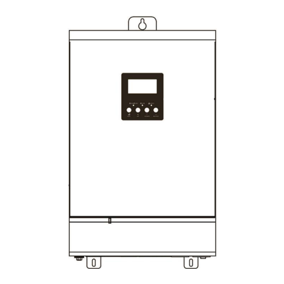
Page 5: Product Overview
Product Overview Single Model Parallel Model 1. LCD display NOTE: For parallel model installation and operation, 2. Status indicator please check separate parallel installation guide for 3. Charging indicator the details. 4. Fault indicator 5. Function buttons 6. Power on/off switch 7. -
Page 6: Installation
INSTALLATION Unpacking and Inspection Before installation, please inspect the unit. Be sure that nothing inside the package is damaged. You should have received the following items inside of package: The unit x 1 User manual x 1 Communication cable x 1 ... -
Page 7: Battery Connection
Install the unit by screwing three screws. It’s recommended to use M5 screws. Battery Connection CAUTION: For safety operation and regulation compliance, it’s requested to install a separate DC over-current protector or disconnect device between battery and inverter. It may not be requested to have a disconnect device in some applications, however, it’s still requested to have over-current protection installed. - Page 8 WARNING: Shock Hazard Installation must be performed with care due to high battery voltage in series. CAUTION!! Do not place anything between the flat part of the inverter terminal and the ring terminal. Otherwise, overheating may occur. CAUTION!! Do not apply anti-oxidant substance on the terminals before terminals are connected tightly.
-
Page 9: Ac Input/Output Connection
AC Input/Output Connection CAUTION!! Before connecting to AC input power source, please install a separate AC breaker between inverter and AC input power source. This will ensure the inverter can be securely disconnected during maintenance and fully protected from over current of AC input. The recommended spec of AC breaker is 50A. CAUTION!! There are two terminal blocks with “IN”... -
Page 10: Pv Connection
5. Make sure the wires are securely connected. CAUTION: Important Be sure to connect AC wires with correct polarity. If L and N wires are connected reversely, it may cause utility short-circuited when these inverters are worked in parallel operation. CAUTION: Appliances such as air conditioner are required at least 2~3 minutes to restart because it’s required to have enough time to balance refrigerant gas inside of circuits. -
Page 11: Final Assembly
Final Assembly After connecting all wirings, please put bottom cover back by screwing two screws as shown below. Communication Connection Please use supplied communication cable to connect to inverter and PC. Insert bundled CD into a computer and follow on-screen instruction to install the monitoring software. For the detailed software operation, please check user manual of software inside of CD. -
Page 12: Operation
OPERATION Power ON/OFF Once the unit has been properly installed and the batteries are connected well, simply press On/Off switch (located on the button of the case) to turn on the unit. Operation and Display Panel The operation and display panel, shown in below chart, is on the front panel of the inverter. It includes three indicators, four function keys and a LCD display, indicating the operating status and input/output power information. -
Page 13: Lcd Display Icons
LCD Display Icons Icon Function description Input Source Information Indicates the AC input. Indicates the PV1 input Indicates the PV2 input Indicates the PV3 input Indicate input voltage, input frequency, PV voltage, battery voltage and charger current. Configuration Program and Fault Information Indicates the setting programs. - Page 14 In battery mode, it will present battery capacity. Load Percentage Battery Voltage LCD Display < 1.717V/cell 1.717V/cell ~ 1.8V/cell Load >50% 1.8 ~ 1.883V/cell > 1.883 V/cell < 1.817V/cell 1.817V/cell ~ 1.9V/cell 50%> Load > 20% 1.9 ~ 1.983V/cell > 1.983 <...
-
Page 15: Lcd Setting
LCD Setting After pressing and holding ENTER button for 3 seconds, the unit will enter setting mode. Press “UP” or “DOWN” button to select setting programs. And then, press “ENTER” button to confirm the selection or ESC button to exit. Setting Programs: Program Description... - Page 16 100A 110A 120A 130A 140A 150A 160A 170A 180A 190A 200A 210A 220A 230A 240A Appliances (default) If selected, acceptable AC input voltage range will be within 90-280VAC. AC input voltage range If selected, acceptable AC input voltage range will be within 170-280VAC.
- Page 17 Restart disable Restart enable (default) Auto restart when overload occurs Restart disable Restart enable (default) Auto restart when over temperature occurs 220V 230V (default) Output voltage 240V 50Hz (default) 60Hz Output frequency 30A (default) Maximum utility charging current 46V (default) Setting voltage point back to utility source when selecting “SBU priority”...
- Page 18 Battery fully charged Setting voltage point back to battery mode when selecting “SBU priority” or 54V (default) “Solar first” in program 01. If this inverter/charger is working in Line, Standby or Fault mode, charger source can be programmed as below: Solar first Solar energy will charge battery as first priority.
- Page 19 Return to default If selected, no matter how users display screen switch display screen, it will (default) automatically return to default display screen (Input voltage /output voltage) Auto return to default after no button is pressed for 1 display screen minute.
-
Page 20: Display Setting
If selected, solar input power will Solar power balance be automatically adjusted enable (Default): according to the following formula: Max. input solar power = Max. battery charging power + Connected load power. Solar power balance: When enabled, solar input If selected, the solar input power Solar power balance power will be automatically will be the same to max. - Page 21 PV3 voltage=60V PV3 voltage Charging current =50A Charging current When total PV charging power is lower than 1kW, it will present xxxW like below chart. Total PV charging power When total PV Charging power is larger than 1kW (≧1KW), it will present x.xkW like below chart. When PV1 charging power is lower than 1kW, it will present xxxW like below chart.
- Page 22 When PV2 Charging power is lower than 1kW, it will present xxxW like below chart. PV2 charging power When PV2 Charging power is larger than 1kW (≧ 1KW), it will present x.xkW like below chart. When PV3 Charging power is lower than 1kW, it will present xxxW like below chart.
- Page 23 When connected load is lower than 1kVA, load in VA will present xxxVA like below chart. Load in VA When load is larger than 1kVA (≧1KVA), load in VA will present x.xkVA like below chart. When load is lower than 1kW, load in W will present xxxW like below chart.
-
Page 24: Operating Mode Description
The third CPU version 00001.02 The third CPU version checking The fourth CPU version 00001.03 The fourth CPU version checking Operating Mode Description Operation mode Description LCD display Charging by utility and PV energy. Standby mode / Power saving mode Charging by utility energy. - Page 25 Charging by PV energy. Fault mode PV energy and utility can Note: charge batteries. *Fault mode: Errors are caused No charging. by inside circuit error or external reasons such as over temperature, output short Power from utility energy. Utility can power loads when circuited and so on.
-
Page 26: Fault Reference Code
Fault Reference Code Fault Code Fault Event Icon on Fan is locked when inverter is off. Over temperature Battery voltage is too high Battery voltage is too low Output short circuited or over temperature is detected by internal converter components. Output voltage is too high. -
Page 27: Specifications
SPECIFICATIONS Table 1 Line Mode Specifications Line Mode (Utility Bypass Mode) Model 5KVA with 2 MPPTs 5KVA with 3 MPPTs Input Voltage Waveform Sinusoidal (utility or generator) Nominal Input Voltage 230Vac Maximum input current Maximum input inrush current 65A peak 100ms Low Loss Voltage 170Vac±... -
Page 28: Table 2 Inverter Mode Specifications
Table 2 Inverter Mode Specifications Inverter Mode Model 5KVA with 2 MPPTs 5KVA with 3 MPPTs Rated Output Power 5000VA/4000W Output Voltage Waveform Pure Sine Wave Output Voltage Regulation 230Vac± 5% Maximum output current 21.7A Maximum output inrush current 65 peak for 100ms Output Frequency 50Hz Power factor range... -
Page 29: Table 3 Charge Mode Specifications
Table 3 Charge Mode Specifications Utility Charging Mode Model 5KVA with 2 MPPTs 5KVA with 3 MPPTs Charging Current (UPS) 2A/10A/20A/30A/40A/50A/60A @ Nominal Input Voltage Flooded Battery 58.4 Bulk Charging Voltage AGM / Gel Battery 56.4 Floating Charging Voltage 54Vdc Charging Algorithm 3-Step Battery Voltage, per cell... - Page 30 Over-temperature Protection Overload, DC short-circuit Protection Prevents reserve current from battery at night Joint Utility and Solar Charging Model 5KVA with 2 MPPTs 5KVA with 3 MPPTs Max Charging Current 180 Amp 240 Amp Default Charging Current 60 Amp Table 4 General Specifications Model 5KVA with 2 MPPTs 5KVA with 3 MPPTs...
-
Page 31: Trouble Shooting
TROUBLE SHOOTING Problem LCD/LED/Buzzer Explanation / Possible cause What to do Unit shuts down LCD/LEDs and buzzer automatically will be active for 3 The battery voltage is too low 1. Re-charge battery. during startup seconds and then (<1.91V/Cell) 2. Replace battery. process. -
Page 32: Appendix I: Approximate Back-Up Time Table
Appendix I: Approximate Back-up Time Table Model Load (VA) Backup Time @ 48Vdc 600Ah (min) Backup Time @ 48Vdc 1200Ah (min) 3678 7728 1000 1608 3678 1500 2412 2000 1626 2500 1290 5KVA 3000 1092 3500 4000 4500 5000 Note: Backup time depends on the quality of the battery, age of battery and type of battery. Specifications of batteries may vary depending on different manufacturers. -
Page 33: Appendix Ii: Parallel Function (Only For Parallel Model)
Appendix II: Parallel function (Only for parallel model) 1. Introduction This inverter can be used in parallel with two different operation modes. 1. Parallel operation in single phase with up to 6 units. The supported maximum output power is 24KW/30KVA. 2. - Page 34 Step 3: Remove two screws as below chart and remove 2-pin and 14-pin cables. Take out the board under the communication board. Step 4: Remove two screws as below chart to take out cover of parallel communication. Step 5: Install new parallel board with 2 screws tightly. Step 6: Re-connect 2-pin and 14-pin to original position.
- Page 35 Step 7: Put communication board back to the unit. Step 8: Put wire cover back to the unit. Now the inverter is providing parallel operation function. 4. Mounting the Unit When installing multiple units, please follow below chart. NOTE: For proper air circulation to dissipate heat, allow a clearance of approx. 20 cm to the side and approx. 50 cm above and below the unit.
- Page 36 Recommended AC input and output cable size for each inverter: Wire Size Torque Value 1 * 8 AWG 1.4~ 1.6Nm You need to connect the cables of each inverter together. Take the battery cables for example: You need to use a connector or bus-bar as a joint to connect the battery cables together, and then connect to the battery terminal.
- Page 37 5-1. Parallel Operation in Single phase Two inverters in parallel: Power Connection Load Communication Connection Three inverters in parallel: Power Connection Load...
- Page 38 Communication Connection Four inverters in parallel: Power Connection Load Communication Connection...
- Page 39 Five inverters in parallel: Power Connection Load Communication Connection Six inverters in parallel: Power Connection Load Communication Connection...
- Page 40 5-2. Support 3-phase equipment Two inverters in each phase: Power Connection Load Communication Connection Four inverters in one phase and one inverter for the other two phases: Power Connection Load Note: It’s up to customer’s demand to pick 4 inverters on any phase. P1: L1-phase, P2: L2-phase, P3: L3-phase.
- Page 41 Three inverters in one phase, two inverters in second phase and one inverter for the third phase: Power Connection Load Communication Connection Three inverters in one phase and only one inverter for the remaining two phases: Power Connection Load Communication Connection...
- Page 42 Two inverters in two phases and only one inverter for the remaining phase: Power Connection Load Communication Connection Two inverters in one phase and only one inverter for the remaining phases: Power Connection Load...
- Page 43 Communication Connection One inverter in each phase: Power Connection Load Communication Connection WARNING: Do not connect the current sharing cable between the inverters which are in different phases. Otherwise, it may damage the inverters. 6. PV Connection Please refer to user manual of single unit for PV Connection. CAUTION: Each inverter should connect to PV modules separately.
- Page 44 7. LCD Setting and Display Setting Program: Program Description Selectable option Single: When the units are used in parallel with single phase, please select “PAL” in program It is required to have at least 3 inverters or Parallel: maximum 6 inverters to support three-phase equipment.
- Page 45 Fault code display: Fault Code Fault Event Icon on Power feedback protection Firmware version inconsistent Current sharing fault Different setting fault on output voltage CAN fault Host loss Synchronization loss Battery voltage detected different AC input voltage and frequency detected different AC output current unbalance AC output mode setting is different 8.
- Page 46 Step 4: Switch on all AC breakers of Line wires in AC input. It’s better to have all inverters connect to utility at the same time. If not, it will display fault 82 in following-order inverters. However, these inverters will automatically restart.
- Page 47 9. Trouble shooting Situation Fault Solution Fault Event Description Code Restart the inverter. Check if L/N cables are not connected reversely in all inverters. For parallel system in single phase, make sure the sharing are Current feedback into connected in all inverters. the inverter is For supporting three-phase system, make sure the sharing cables are detected.
Need help?
Do you have a question about the Axpert Plus Duo and is the answer not in the manual?
Questions and answers