Table of Contents
Advertisement
Advertisement
Table of Contents

Related Manuals for Voltronic Power EPS 5KW


Summary of Contents for Voltronic Power EPS 5KW
- Page 1 User Manual EPS 5KW INVERTER / CHARGER Version: 1.0...
-
Page 2: Table Of Contents
Table of Contents ABOUT THIS MANUAL ............................. 1 Purpose ................................1 Scope ................................1 SAFETY INSTRUCTIONS ..........................1 INTRODUCTION ............................... 2 Features ................................2 Basic System Architecture ..........................2 Product Overview ............................. 3 INSTALLATION ..............................4 Unpacking and Inspection..........................4 Installation ................................ -
Page 3: About This Manual
ABOUT THIS MANUAL Purpose This manual describes the assembly, installation, operation and troubleshooting of this unit. Please read this manual carefully before installations and operations. Keep this manual for future reference. Scope This manual provides safety and installation guidelines as well as information on tools and wiring. SAFETY INSTRUCTIONS WARNING: This chapter contains important safety and operating instructions. -
Page 4: Introduction
INTRODUCTION This is a multi-functional inverter/charger, combining functions of inverter and battery charger to offer uninterruptible power for office and home appliances. Its comprehensive LCD display offers user-configurable parameters, such as battery charging current, and acceptable inputs voltage by setting easy-accessible buttons to fit different application. -
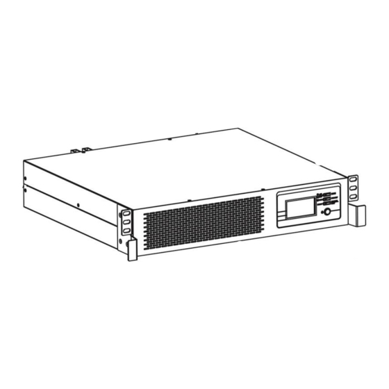
Page 5: Product Overview
Product Overview Operation panel RS-232 communication port AC input terminal AC output terminal Battery input Circuit breaker Parallel communication ports Share current ports Dry contact 10. Communication ports... -
Page 6: Installation
INSTALLATION Unpacking and Inspection Before installation, please inspect the unit. Be sure that nothing inside the package is damaged. You should have received the following items inside the package: The unit x 1 User manual x 1 Parallel cable x 2 ... -
Page 7: Battery Connection
Battery Connection CAUTION: For safety operation and regulation compliance, it’s requested to install a separate DC over-current protector or disconnect device between battery and inverter. It may not be requested to have a disconnect device in some applications, however, it’s still requested to have over-current protection installed. Please refer to the table below to select proper amperage, required fuse or breaker size. -
Page 8: Ac Input/Output Connection
CAUTION!! Do not place anything between the flat part of the inverter terminal and the ring terminal. Otherwise, overheating may occur. CAUTION!! Do not apply anti-oxidant substance on the terminals before terminals are connected tightly. CAUTION!! Before making the final DC connection or closing DC breaker/disconnector, be sure positive (+) must be connected to positive (+) and negative (-) must be connected to negative (-). -
Page 9: Communication Connection
4. Then, insert AC output wires according to polarities indicated on terminal block and tighten terminal screws. Be sure to connect PE protective conductor ( ) first. →Ground (yellow-green) L→LINE (brown or black) N→Neutral (blue) 5. Make sure the wires are securely connected. CAUTION: Appliances such as air conditioner are required at least 2~3 minutes to restart because it’s required to have enough time to balance refrigerant gas inside of circuits. -
Page 10: Operation
OPERATION Power ON/OFF Once the unit has been properly installed and the batteries are connected well, simply press On/Off switch to turn on the unit. Operation and Display Panel The operation and display panel, shown in below chart, is on the front panel of the inverter. It includes three indicators, three function keys and a LCD display, indicating the operating status and input/output power information. -
Page 11: Lcd Display Icons
LCD Display Icons Icon Function description Input Source Information Indicates input voltage, input frequency and battery voltage, charging power or setting value. Output Information Indicates output voltage, output frequency, setting program NO or fault code. Indicates percentage of load Battery Information Indicates battery level by 0-24%, 25-49%, 50-74% and 75-100% in battery mode and charging status. - Page 12 < 1.817V/cell 1.817V/cell ~ 1.9V/cell 50%> Load > 20% 1.9 ~ 1.983V/cell > 1.983 < 1.867V/cell 1.867V/cell ~ 1.95V/cell Load < 20% 1.95 ~ 2.033V/cell > 2.033 Load Information Indicates unit is overload. Indicates the load level by 0-24%, 25-50%, 50-74% and 75-100%. 0%~25% 25%~50% 50%~75%...
-
Page 13: Lcd Setting
LCD Setting After pressing and holding ENTER button for 3 seconds, the unit will enter setting mode. Press “SELECT” button to select setting programs. And then, press “ENTER” button to confirm the selection or ESC button to exit. Setting Programs: Program Description Selectable option... - Page 14 Restart disable Restart enable (default) Auto restart when overload occurs Restart disable Restart enable (default) Auto restart when temperature is too high Alarm on (default) Alarm off Alarm control Return to default If selected, no matter how users display screen switch display screen, it will (default) automatically return to default display...
-
Page 15: Display Setting
Display Setting To switch display of the LCD information in turn, press “SELECT” key. The selectable information is switched to input voltage/output voltage, input frequency, , battery display in order as below: Utility charging power voltage/output frequency and main CPU Version. Selectable information LCD display Input Voltage=220V, output voltage=220V... -
Page 16: Operating Mode Description
Description of Operating Mode Operation mode Description LCD display Charging by utility. Standby mode / Power saving mode Note: *Standby mode: The inverter is not turned on yet but at this time, the No output is supplied by the unit inverter can charge battery without AC but it still can charge batteries. -
Page 17: Fault Reference Code
Fault Reference Code Fault Code Fault Event Icon on Fan is locked when inverter is off. Over temperature Battery voltage is too high Output short circuited or over temperature is detected by internal converter components. Output voltage is too high. Overload time out Bus voltage is too high Bus soft start failed... -
Page 18: Specifications
SPECIFICATIONS Table 1 Line Mode Specifications INVERTER MODEL Input Voltage Waveform Sinusoidal (utility or generator) Nominal Input Voltage 220Vac Low Loss Voltage 170Vac± 3V Low Loss Return Voltage 180Vac± 3V High Loss Voltage 255Vac± 3V High Loss Return Voltage 245Vac± 3V Max AC Input Voltage 300Vac Nominal Input Frequency... -
Page 19: Safety Certification
Table 3 Charge Mode Specifications Utility Charging Mode INVERTER MODEL Charging Current (UPS) Default: 30A, Max.: 60A @ Nominal Input Voltage Bulk Charging Voltage 56.4Vdc Floating Charging Voltage 54Vdc Charging Algorithm 3-Step Battery Voltage, per cell Charging Current, % 2.43Vdc (2.35Vdc) Voltage 2.25Vdc 100%... -
Page 20: Trouble Shooting
TROUBLE SHOOTING Explanation / Possible Problem LCD/LED/Buzzer What to do cause Unit shuts down LCD/LEDs and buzzer will automatically The battery voltage is too low 1. Re-charge battery. be active for 3 seconds during startup (<1.91V/Cell) 2. Replace battery. and then complete off. process. -
Page 21: Appendix I: Parallel Function
Appendix I: Parallel function 1. Introduction This inverter can be used in parallel with two different operation modes. 1. Parallel operation in single phase with up to 6 units. The maximum supported output power is 30KW. 2. Six units work together at its maximum to support three-phase equipment. Four units support one phase at its maximum. - Page 22 Recommended specification of battery breaker for each inverter: Model One unit* 100A/60VDC *If you want to use only one breaker at the side of battery for the whole system, the rating of the breaker should be X times to the current of 1 unit. “X” indicates the number of inverters connected in parallel. Recommended specification of AC input breaker for single-phase application: Inverter # 2 units...
- Page 23 Communication Connection Three inverters in parallel: Power Connection Communication Connection Four inverters in parallel: Power Connection...
- Page 24 Communication Connection Five inverters in parallel: Power Connection Communication Connection Six inverters in parallel: Power Connection Communication Connection...
- Page 25 4-2. Support 3-phase equipment Two inverters in each phase: Power Connection Communication Connection Four inverters in one phase and one inverter for the other two phases: Power Connection Note: It’s up to customer’s demand to pick 4 inverters in any phase. P1: L1-phase, P2: L2-phase, P3: L3-phase.
- Page 26 Three inverters in one phase, two inverters in second phase and one inverter for the third phase: Power Connection Communication Connection Three inverters in one phase and only one inverter for the remaining two phases: Power Connection Communication Connection...
- Page 27 Two inverters in two phases and only one inverter for the remaining phase: Power Connection Communication Connection Two inverters in one phase and only one inverter for the remaining phases: Power Connection...
- Page 28 Communication Connection One inverter in each phase: Power Connection Communication Connection WARNING: Do not connect the sharing cable between the inverters in different phases. Otherwise, it may damage the inverters.
- Page 29 5. LCD Setting and Display Setting Program: Program Description Selectable option When the units are used in parallel with single phase, please select “PAL” in Single: program 01. It is required to have at least 3 inverters or maximum 6 inverters to support three-phase equipment.
- Page 30 Step 3: Turn on each unit. LCD display in Master unit LCD display in Slave unit NOTE: Master and slave units are randomly defined. Step 4: Switch on all AC breakers of Line wires in AC input. It’s better to have all inverters connect to utility at the same time, so they will work normally.
- Page 31 7. Trouble shooting Situation Fault Solution Fault Event Description Code Restart the inverter. Check if L/N cables are not connected reversely in all inverters. For parallel system in single phase, make sure the sharing current Current feedback into the cables are connected in all inverters. inverter is detected.
-
Page 32: Appendix Ii: Approximate Back-Up Time Table
Appendix II: Approximate Back-up Time Table Model Load (W) Backup Time @ 48Vdc 100Ah (min) Backup Time @ 48Vdc 200Ah (min) 1288 1200 1600 2000 2400 2800 3200 3600 4000 5000 Note: Backup time depends on the quality of the battery, age of battery and type of battery. Specifications of batteries may vary depending on different manufacturers.
Need help?
Do you have a question about the EPS 5KW and is the answer not in the manual?
Questions and answers