Table of Contents
Advertisement
Advertisement
Table of Contents

Related Manuals for Voltronic Power EnerSolar 3K PV


Summary of Contents for Voltronic Power EnerSolar 3K PV
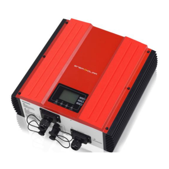
- Page 1 User Manual EnerSolar 3K PV Inverter...
-
Page 2: Table Of Contents
Table Of Contents 1. Introduction ............. 3 2. Important Safety Warning ......... 4 3. Unpacking & Overview ..........6 4. Installation ............... 6 5. Grid (AC) Connection ..........8 6. PV Module (DC) Connection ........9 7. Commissioning ............11 8. -
Page 3: Introduction
1. Introduction 1-1. Overview The EnerSolar inverter is designed to convert solar electric (photovoltaic or PV) power into utility-grade electricity that can be sold to the local power company. This inverter is allowed for 2 arrays of PV modules. Embedded with two smart independent MPPTs, the EnerSolar PV inverter can operate at optimum power output voltage. -
Page 4: Important Safety Warning
Important: The inverter will reduce its output generation to protect its electronic circuits from overheating and any damage under high temperature environment. For maximum power output in high temperature, it’s recommended to mount the inverter in a shaded location with good ventilation. - Page 5 WARNING! Before installing and using this inverter, read all instructions and cautionary markings on the inverter and all appropriate sections of this guide. WARNING! Normally grounded conductors may be ungrounded and energized when a ground fault is indicated. WARNING! This inverter is heavy. It should be lifted by at least two persons. CAUTION! Authorized service personnel should reduce the risk of electrical shock by disconnecting both the AC and DC power from the inverter before attempting any maintenance or cleaning or working on any circuits connected to the inverter.
-
Page 6: Unpacking & Overview
3. Unpacking & Overview 3-1. Packing List Before installation, please inspect the unit. Be sure that nothing inside the package is damaged. You should have received the following items inside of package: Inverter unit PV connectors x 2 sets Mounting plate Software CD Manual 3-2. - Page 7 side and approx. 50 cm above and below the unit. Dusty conditions on the unit may impair the performance of this inverter. The ambient temperature should be between -25°C and 60°C to ensure optimal operation. The recommended installation position is to be adhered to (vertical). ...
-
Page 8: Grid (Ac) Connection
5. To avoid theft, you may add a lock between mounting plate and inverter. NOTE: Please follow below requirements to choose suitable lock. 5. Grid (AC) Connection 5-1. Preparation Before connecting to AC utility, please install a separate circuit breaker between inverter and AC utility. -
Page 9: Pv Module (Dc) Connection
CAUTION: To prevent risk of electric shock, ensure the ground wire is properly earthed before operating the solar inverter. 6. PV Module (DC) Connection CAUTION: Before connecting to PV modules, please install a separate circuit breaker between inverter and PV modules. NOTE: Please use 500VDC/12A circuit breaker. - Page 10 Positive terminal connection Step 2: Remove the cover of PV modules. Check the input voltage of PV modules. The acceptable input voltage of the solar inverter is 125VDC - 500VDC. The maximum current load of each PV input connector is 10A. CAUTION: Exceeding the maximum input voltage can destroy the unit!! Check the system before wire connection.
-
Page 11: Commissioning
Step 5: Insert the sealing caps provided into unused DC connectors on the inverter. CAUTION: Never directly touch terminals of the inverter. It will cause lethal electric shock. CAUTION: Never disconnect running inverter from AC Grid. If it’s necessary to turn off the inverter, disconnect the AC breaker first and then DC breaker next. -
Page 12: Operation
Or, if red LED lights up, there has been an error. Please inform your installer. 8. Operation 8-1. Interface This LCD panel with 3 indicators shows current status and value of your system. This display is operated by four buttons. -
Page 13: Button Definition
Each indicates 150VDC. When input voltage is below 100VDC, icon will flash. When both of PV modules are not connected, icon will flash. Indicates the Inverter circuit is working. Indicates grid. Indicates energy generated in graphic bar. 8-3. Button Definition Button Function Up Button... - Page 14 Frequency or voltage of AC output Procedure LCD Display Energy generation Energy generation display of selected year in monthly basis Procedure: LCD Display: Energy generation display of selected month in daily basis Procedure: LCD Display: Press “up” button to display info from 17 to 30...
- Page 15 Energy generation display of selected date in hourly basis Procedure: LCD Display: Press “down” button to display info in AM 8-5. Operation Mode & Display Mode LCD Display Indicator Alarm Description Power on All three The inverter is mode LEDs light initializing.
- Page 16 8-6. Self test Please follow below steps to complete the self-test: Step 1: Connect the inverter to your computer, and start up the SolarPower that installed in your computer. Step 2: Click the menu into self-test. Step 3: Click “start” and then “yes”. Step 4: Wait for a moment and then popup a interface, it displays the result of the self-test.
-
Page 17: Maintenance & Cleaning
9. Maintenance & Cleaning Check the following points to ensure proper operation of whole solar system at regular intervals. Heat sink of the inverter should be cleaned from dust. WARNING: Although the inverter is designed in sealed IP65 enclosure, it is not recommended to use a pressure washer to clean the inverter, or use other high pressure cleaning methods that could allow water or moisture to enter the unit. -
Page 18: Trouble Shooting
10. Trouble Shooting When errors or fault conditions occur, it will display icon in LCD. Please contact your installer to solve the problem. 10-1. Warning Situation There are 5 situations defined as warnings. When a warning situation occurs, icon will flash and the fault code area will display “WR”... -
Page 19: Specifications
11. Specifications MODEL EnerSolar 3KW INPUT (DC) Max. DC Power 3200W Maximum DC Voltage 500 VDC 150 VDC ~ 450 VDC MPP Voltage Range 370 VDC DC Nominal Voltage 116VDC / 150VDC Start-up Voltage / Initial Feeding Voltage Maximum Input Current / Per String 2 x 10A / 10 A Number of MPP Trackers / Strings per MPP 2 / A:1;B:1... - Page 21 Voltronic Power Technology (Shenzhen) Corporation ADD: 1-4F, Building 5, YuSheng lndustrial Park, No.467, Section Xixiang, National Highway 107, Xixiang, Bao An District, Shenzhen, China TEL: +886-2-27918296 FAX: +886-2-87918216...
Need help?
Do you have a question about the EnerSolar 3K PV and is the answer not in the manual?
Questions and answers