Symbol MC909X User Manual
Hide thumbs
Also See for MC909X:
- User manual (246 pages) ,
- Integrator manual (296 pages) ,
- User manual (21 pages)
Table of Contents
Advertisement
Quick Links
Advertisement
Table of Contents
Troubleshooting

Related Manuals for Symbol MC909X


Summary of Contents for Symbol MC909X
- Page 1 MC909X Mobile Computer User Guide...
- Page 3 MC909X User Guide 72E-72215-03 Rev A March 2006...
-
Page 4: Patents
Symbol reserves the right to make changes to any software or product to improve reliability, function, or design. Symbol does not assume any product liability arising out of, or in connection with, the application or use of any product, circuit, or application described herein. -
Page 5: Revision History
Revision History Changes to the original manual are listed below: Change Date Description Rev A Initial release. -02 Rev A Add MC9090-K/S, MC9090-G and MC9094-K/S with Windows Mobile 5.0. -03 Rev A Add MC9097 support. -
Page 7: Table Of Contents
Starting the Mobile Computer ..................1-9 Calibrating the Screen ....................1-10 Checking Battery Status ....................1-10 SIM Card ........................1-11 Stylus ..........................1-13 MC9090-G Strap ......................1-14 MC909X-K Strap ......................1-15 MC909X-S Strap ......................1-17 Battery Management ..................... 1-18 Battery Saving Tips ....................1-18... - Page 8 LED Indicators ......................2-9 Keypads ........................2-10 28-Key Keypad for MC909X-G/K ................2-10 28-Key Keypad for MC909X-S................. 2-12 38-Key Numeric/Function Keypad for MC909X-S ........... 2-16 38-Key Alpha/Shifted Numeric Keypad for MC909X-S..........2-20 43-Key Keypad for MC909X-G/K................2-23 53-Key Keypad for MC909X-G/K................2-27 3270 Emulator Keypad for MC909X-G/K..............
- Page 9 Table of Contents Performing a Warm Boot ................... 2-51 Performing a Cold Boot ..................2-51 Waking the Mobile Computer .................. 2-52 Chapter 3: Using Bluetooth Introduction ........................3-1 Adaptive Frequency Hopping ..................3-1 Security ......................... 3-2 Turning the Bluetooth Radio Mode On and Off ............. 3-2 Disabling Bluetooth ....................
- Page 10 MC909X User Guide Discovery Tab ......................3-27 Virtual COM Port Tab ....................3-28 Miscellaneous Tab ....................3-29 Chapter 4: Using MC9094 Phone Introduction ........................4-1 Accessing the Phone Keypad ..................4-1 Making a Call Using the Keypad ................4-2 Answering a Call ......................
- Page 11 Table of Contents Making Calls from Recent Call List ................. 5-7 Receiving Phone Calls ....................5-8 Walkie-Talkie Calls ....................... 5-9 Sending Call Alerts ....................5-9 Making Walkie-Talkie Calls ..................5-10 Making Walkie-Talkie Calls from Contacts ............. 5-11 Receiving Call Alerts ....................5-12 Receiving Walkie-Talkie Calls .................
- Page 12 MC909X User Guide Serial/USB Connection ................... 6-14 Using the MSR ......................6-14 Cable Adapter Module ....................6-15 Attaching and Removing ..................6-16 Setup ........................6-16 Battery Charging Indicators ..................6-17 Serial/USB Connection ................... 6-17 Universal Battery Charger (UBC) Adapter ..............6-18 Inserting and Removing a Battery ................
-
Page 13: About This Guide
Screens and windows pictured in this guide are samples and can differ from actual screens. NOTE Documentation Set The documentation set for the MC909X is divided into guides that provide information for specific user needs. Microsoft Application Guide - describes how to use Microsoft developed applications. •... - Page 14 MC909X User Guide...
-
Page 15: Configurations
• Chapter 2, Operating the MC909X, explains how to use the mobile computer. This includes instructions for powering on and resetting the mobile computer, entering and capturing data. Chapter 3, Using Bluetooth, explains how to perform Bluetooth functionality on the mobile computer. -
Page 16: Notational Conventions
Regulatory, contains the accessory power supply regulatory compliance statements. Notational Conventions The following conventions are used in this document: • “Mobile computer” refers to the Symbol MC909X series of hand-held computers. • Italics are used to highlight the following: Chapters and sections in this guide Related documents •... -
Page 17: Service Information
Call the Support Center from a phone near the equipment so that the service person can try to talk through the problem. If the equipment is found to be working properly and the problem is symbol readability, the Support Center will request samples of bar codes for analysis at our plant. - Page 18 MC909X User Guide Country/Region Address Telephone Asia/Pacific Symbol Technologies Asia, Inc. Tel: +65-6796-9600 (Singapore Branch) Fax: +65-6337-6488 230 Victoria Street #12-06/10 Bugis Junction Office Tower Singapore 188024 Australia Symbol Technologies Pty. Ltd. 1-800-672-906 (Inside Australia) 432 St. Kilda Road +61-3-9866-6044 (Outside Australia Melbourne, Victoria 3004 Austria/Österreich...
- Page 19 Call Center: +46 8 445 29 29 (international) Box 1354 Support E-Mail: S-171 26 SOLNA Sweden.Support@se.symbol.com Sweden Visit/shipping address: Symbol Technologies AB Solna Strandväg 78 S-171 54 SOLNA Sweden If you purchased your Symbol product from a Symbol Business Partner, contact that Business Partner for service.
- Page 20 MC909X User Guide...
-
Page 21: Chapter 1: Getting Started
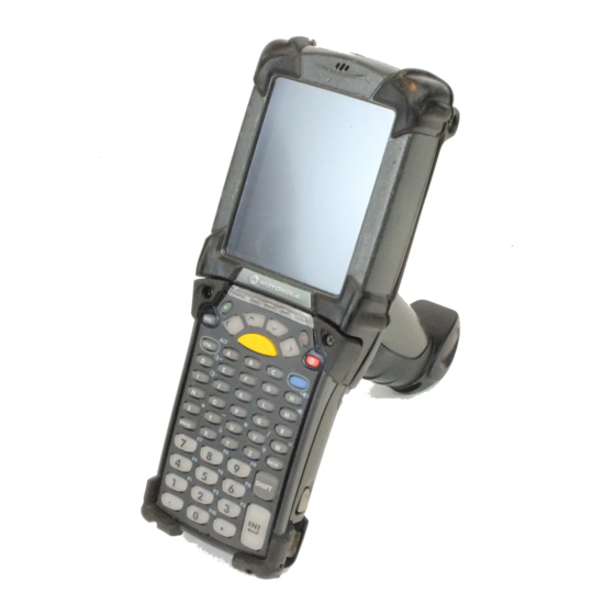
Getting Started Chapter 1 Chapter 1 Chapter 1 Getting Started Introduction This chapter lists the accessories for the mobile computer and explains how to install and charge the batteries, replace the strap and start the mobile computer for the first time. Microphone (Windows Indicator LED Bar Touch Screen... - Page 22 1 - 2 MC909X User Guide Microphone Touch Screen Indicator LED Bar Power Scan Button Scan Button or Walkie-Talkie Button Keypad on MC9097-K Battery Release Latch Exit Window Exit Window Headphone Stylus Jack Scan Button Scan Scan Button (MC9094-K) Button...
- Page 23 Scan Button Scan Button or Walkie-Talkie Button Keypad on MC9097-S Exit Window Exit Window Stylus Headphone Jack Scan Scan Scan Button Button Button (MC9094-S) Walkie-Talkie Strap Button (MC9097-S) Stylus SIM Door Battery Release Latch MC9090-S MC9094-S MC9097-S MC909X-S Figure 1-3...
-
Page 24: Unpacking The Mobile Computer
• Quick Start Guide (poster). • Inspect the equipment for damage. If you are missing any equipment or if you find any damaged equipment, contact the Symbol Technologies Support Center immediately. See page ix for contact information. Accessories Table 1-1... -
Page 25: Getting Started
USB connection. Software Symbol Mobility Developer Kits available at: http://devzone.symbol.com. Device Configuration Package (DCPforMC9090c50) and Platform SDK (PSDK9090c50) for MC9090-G with Windows CE 5.0 only, available at: http://devzone.symbol.com. -
Page 26: Installing And Removing The Main Battery
1 - 6 MC909X User Guide Installing and Removing the Main Battery Installing the Main Battery Before using the mobile computer, install a lithium-ion battery by sliding the battery into the mobile computer as shown in Figure 1-4. Ensure the battery is fully inserted. Two audible clicks can be heard as the battery is fully inserted. A NOTE partially inserted battery may result in unintentional data loss. - Page 27 This can be accomplished via the SetDevicePower() API (refer to the SMDK Help File for Symbol Mobile Computers) or via the Control Panel application (tap Start - 9000 Demo - Ctl Panel icon). To charge the main battery: Ensure the accessory used to charge the main battery is connected to the appropriate power source.
-
Page 28: Charging Spare Batteries
1 - 8 MC909X User Guide Mobile Computer LED Charge Indicators (Continued) Table 1-2 Indication Fast Blinking Amber Error in charging; check placement of the mobile computer. Slow Blinking Amber Mobile computer is charging. Solid Amber Charging complete. Note: When the battery is initially inserted in the mobile computer, the amber LED flashes once if the battery power is low or the battery is not fully inserted. -
Page 29: Starting The Mobile Computer
When a battery is fully inserted in a mobile computer for the first time, upon the mobile computer’s first power up, the device boots and powers on automatically. When the mobile computer is powered on for the first time, it initializes its system. The Symbol splash screen (Figure... -
Page 30: Calibrating The Screen
1 - 10 MC909X User Guide MC9090/4 MC9097 Symbol Splash Window Figure 1-7 Calibrating the Screen To calibrate the screen so the cursor on the touch screen aligns with the tip of the stylus: Using the stylus carefully press and briefly hold the tip of stylus on the center of each target that appears on the screen. -
Page 31: Sim Card
Getting Started 1 - 11 SIM Card NOTE Subscriber Identification Module (SIM) card is only used in the MC9094 and MC9097 configurations. The SIM card, or smart card, is required for MC9094 (GPRS) phone service and must be obtained from the phone service provider. - Page 32 1 - 12 MC909X User Guide SIM Holder Unlock SIM Case Figure 1-9 Insert the SIM card, as shown in Figure 1-10, with the cut edge of the card facing out and the contacts facing down. Lower the SIM holder.
-
Page 33: Stylus
Make a call to verify connection. NOTE For detailed information about WWAN activation and settings, refer to the MC909X Integrator Guide. On the MC9097, if the SIM door is removed without removing the SIM card, you must warm boot the mobile computer. -
Page 34: Mc9090-G Strap
1 - 14 MC909X User Guide MC9090-G Strap The strap may be moved to either the left or right side of the mobile computer to suit user preferences. To reposition the strap: Disconnect the metal clip at the handle. Open strap loop and slide the handstrap through the loop. -
Page 35: Mc909X-K Strap
Getting Started 1 - 15 MC909X-K Strap The strap may be moved to either the left or right side of the mobile computer to suit user preferences. To reposition the MC909X-K strap: Lift the loop end of the strap over the button. Loop... - Page 36 1 - 16 MC909X User Guide Screws Strap Bracket Remove Strap Bracket Figure 1-15 Lift the loop end of the strap over the button. Pull the loop through the connection post. Remove the battery. Reverse the procedure to re-attach the strap.
-
Page 37: Mc909X-S Strap
The strap may be moved to either the left or right side of the mobile computer to suit user preferences. To reposition the MC909X-S strap, attach the MC909X-S strap to either the left or right side of the mobile computer to suit user preferences. To reposition the strap: Remove the screw securing the bottom of the strap to the device. -
Page 38: Battery Management
1 - 18 MC909X User Guide Battery Management Battery Saving Tips Leave the mobile computer connected to AC power at all times when not in use. • Set the mobile computer to turn off after a short period of non-use. -
Page 39: Turning The Radios Off
Getting Started 1 - 19 On devices with Windows CE 5.0, tap > > > icon > tab. Start Settings Control Panel Keylight Battery Power On devices with Windows Mobile 5.0, tap > > tab > icon > tab. Start Settings System Keylight... -
Page 40: Wlan Radio On Windows Mobile 5.0
1 - 20 MC909X User Guide WLAN Radio on Windows Mobile 5.0 To turn off the WLAN radio tap the icon at the bottom of the Today screen and Wireless Connection Status select . A red X appears across the icon indicating that the radio is disabled (off). -
Page 41: Chapter 2 Operating The Mc909X
Operating the MC909X Chapter 2 Chapter 2 Chapter 2 Operating the MC909X Introduction This chapter explains the physical buttons, status icons and controls on the mobile computer, how to use the mobile computer, including instructions for powering on and resetting the mobile computer, using the stylus and a headset, entering information and scanning. - Page 42 2 - 2 MC909X User Guide Status Icons (Continued) Table 2-1 Status Icon Description This icon indicates that the main battery is charging or that the terminal is operating on AC power. Double tapping on this icon opens the window.
-
Page 43: Status Icons (Windows Mobile 5.0)
Operating the MC909X 2 - 3 Status Icons (Windows Mobile 5.0) Status Bar at the top of the window displays the current time, battery status and communication status. Status Bar Status Icons Start Button Volume Icon Date/Time Status Bar Figure 2-2 Status icons are shown in the to indicate present status of the mobile computer. -
Page 44: Command Bar
2 - 4 MC909X User Guide Status Icons (Continued) Table 2-2 Icon Function Description WWAN Call missed. Voice call. Voice call in progress. Calls are forwarded. Call on hold. Antenna/signal icon: wireless on/good signal. Antenna/signal icon: wireless off. Antenna/signal icon: no service or searching. -
Page 45: Speaker Icon
Operating the MC909X 2 - 5 Command Bar Icons Table 2-3 Icon Description Wireless connection status icon. Indicates WLAN signal strength and opens the Wireless Applications menu. icon appears in the task tray and indicates that the Bluetooth radio is on. -
Page 46: Battery Icon
2 - 6 MC909X User Guide NOTE Use can also adjust the system volume using the Sounds & Notifications window or by pressing the Blue key and 6 or the Blue key and 7. Battery Icon Battery icons display on the... -
Page 47: Instant Message Icon
Operating the MC909X 2 - 7 Digital Clock Analog Clock Time Icon Format Menu Figure 2-7 To display current date, time and appointments: Tap the icon to display the dialog box. Time Time and Next Appointment Current Date and Time... -
Page 48: Multiple Notification Icon
2 - 8 MC909X User Guide Multiple Notification Icon icon appears when two or more message notifications occur. Tap the icon to display Multiple Notification the multiple notification icons. Multiple Notifications Icon Figure 2-11 Locking the Mobile Computer (Windows Mobile 5.0 Only) Use the Device Lock feature to prevent use of the device. -
Page 49: Led Indicators
Figure 2-13 Tap Unlock on the window. Unlock Device LED Indicators The MC909X has an LED Indicator Bar that contains LEDs that indicate scanning and charging status. Table describes the LED indications. LED Indicator Bar MC909X LEDs Indicator Bar Figure 2-14... -
Page 50: Keypads
The modular keypads can be changed in the field, as necessary, to support specialized applications. Refer to the MC909X Integrator Guide for installation and removal procedures. NOTE For information about using the soft keyboard input panel, refer to the Microsoft Application Guide for Symbol Devices. - Page 51 Operating the MC909X 2 - 11 28-Key Keypad for MC909X-G/K Figure 2-15...
-
Page 52: 28-Key Keypad For Mc909X-S
2 - 12 MC909X User Guide 28-Key Keypad for MC909X-S The 28-key keypad contains a Power button, application keys, scroll keys and function keys. The keypad is color-coded to indicate the alternate function key (blue) values. Note that keypad functions can be changed by an application so the mobile computer’s keypad may not function exactly as described. - Page 53 Parm name = “GreenKeyOverride” value = “xx”, where xx is the new APP key code. Parm name = “RedKeyOverride” value = “xx”, where xx is the new APP key code. Refer to the MC909X Integrator Guide for instruction on updating the registry using XML Provisioning.
- Page 54 2 - 14 MC909X User Guide 28-Key Descriptions (Continued) Table 2-5 Description Alphanumeric In default state, produces the numeric value on the key. In Alpha state, produces the lower case alphabetic characters on the key. Each key G HI J K L M N O press produces the next alphabetic character in sequence.
- Page 55 XML Provisioning file with the following entries: Characteristic type =”HKEY_LOCAL_MACHINE\HARDWARE\DEVICEMAP\KEYBD” Para name = “SpecialEnterTabKey” value = 0 Refer to the MC909X Integrator Guide for instruction on updating the registry using XML Provisioning. Period/Decimal Point In default state, produces a period for alpha entries and a decimal point for numeric entries.
-
Page 56: 38-Key Numeric/Function Keypad For Mc909X-S
2 - 16 MC909X User Guide 38-Key Numeric/Function Keypad for MC909X-S The 38-key numeric/function keypad contains a Power button, application keys, scroll keys and a function key. The keypad is color-coded to indicate the alternate function key (blue) values and the alternate alpha key (orange) values. - Page 57 Parm name = “GreenKeyOverride” value = “xx”, where xx is the new APP key code. Parm name = “RedKeyOverride” value = “xx”, where xx is the new APP key code. Refer to the MC909X Integrator Guide for instruction on updating the registry using XML Provisioning.
- Page 58 2 - 18 MC909X User Guide 38-Key Numeric/Function for MC909X-S Keypad Descriptions (Continued) Table 2-6 Description Alpha-lock (orange) Press and release the orange alpha-lock key to activate the keypad alternate alpha-lock functions (shown on the keypad in orange). The LED above the key lights and the icon appears at the bottom of the screen.
- Page 59 Microsoft Word or Notes application to exit. To make the applications work properly, create an XML Provisioning file with the following entries: Characteristic type =”HKEY_LOCAL_MACHINE\HARDWARE\DEVICEMAP\KEYBD” Para name = “SpecialEnterTabKey” value = 0 Refer to the MC909X Integrator Guide for instruction on updating the registry using XML Provisioning.
-
Page 60: 38-Key Alpha/Shifted Numeric Keypad For Mc909X-S
2 - 20 MC909X User Guide 38-Key Alpha/Shifted Numeric Keypad for MC909X-S The 38-key alpha/shifted numeric keypad contains a Power button, application keys, scroll keys and a function key. The keypad is color-coded to indicate the alternate function key (blue) values and the alternate numeric key (orange) values. - Page 61 Parm name = “GreenKeyOverride” value = “xx”, where xx is the new APP key code. Parm name = “RedKeyOverride” value = “xx”, where xx is the new APP key code. Refer to the MC909X Integrator Guide for instruction on updating the registry using XML Provisioning.
- Page 62 Microsoft Word or Notes application to exit. To make the applications work properly, create an XML Provisioning file with the following entries: Characteristic type =”HKEY_LOCAL_MACHINE\HARDWARE\DEVICEMAP\KEYBD” Para name = “SpecialEnterTabKey” value = 0 Refer to the MC909X Integrator Guide for instruction on updating the registry using XML Provisioning.
-
Page 63: 43-Key Keypad For Mc909X-G/K
Operating the MC909X 2 - 23 43-Key Keypad for MC909X-G/K The 43-key keypad contains a Power button, application keys, scroll keys and a function key. The keypad is color-coded to indicate the alternate function key (blue) values and the alternate ALPHA key (orange) values. - Page 64 Parm name = “GreenKeyOverride” value = “xx”, where xx is the new APP key code. Parm name = “RedKeyOverride” value = “xx”, where xx is the new APP key code. Refer to the MC909X Integrator Guide for instruction on updating the registry using XML Provisioning.
- Page 65 Operating the MC909X 2 - 25 43-Key Keypad Descriptions (Continued) Table 2-8 Description Alpha/Application These keys can have an application assigned to the function value and have an alpha value assigned when used with the ALPHA function key. On Windows Mobile 5.0 devices: F6 and F7 keys cannot be remapped and are dedicated by the Operating System to control volume level.
- Page 66 Microsoft Word or Notes application to exit. To make the applications work properly, create an XML Provisioning file with the following entries: Characteristic type =”HKEY_LOCAL_MACHINE\HARDWARE\DEVICEMAP\KEYBD” Para name = “SpecialEnterTabKey” value = 0 Refer to the MC909X Integrator Guide for instruction on updating the registry using XML Provisioning.
-
Page 67: 53-Key Keypad For Mc909X-G/K
Operating the MC909X 2 - 27 53-Key Keypad for MC909X-G/K There are two physical configurations of the 53-key keypad, however both of the keypads are functionally identical. The 53-key keypad contains a Power button, application keys, scroll keys and function keys. The keypad is color-coded to indicate the alternate function key (blue) values. - Page 68 Parm name = “GreenKeyOverride” value = “xx”, where xx is the new APP key code. Parm name = “RedKeyOverride” value = “xx”, where xx is the new APP key code. Refer to the MC909X Integrator Guide for instruction on updating the registry using XML Provisioning.
- Page 69 Operating the MC909X 2 - 29 53-Key Descriptions (Continued) Table 2-9 Description Numeric/Application Numeric value keys - can have applications assigned with function key(s). For Windows Mobile 5.0 devices: F6 and F7 keys cannot be remapped and are dedicated by the Operating System to control volume level. When these keys are pressed, Shell.exe traps them and displays the volume adjustment window.
- Page 70 Microsoft Word or Notes application to exit. To make the applications work properly, create an XML Provisioning file with the following entries: Characteristic type =”HKEY_LOCAL_MACHINE\HARDWARE\DEVICEMAP\KEYBD” Para name = “SpecialEnterTabKey” value = 0 Refer to the MC909X Integrator Guide for instruction on updating the registry using XML Provisioning.
-
Page 71: 3270 Emulator Keypad For Mc909X-G/K
Operating the MC909X 2 - 31 3270 Emulator Keypad for MC909X-G/K There are two physical configurations of the 3270 emulator keypad, however both of the keypads are functionally identical. The 3270 emulator keypad contains a Power button, application keys, scroll keys and a function key. - Page 72 Parm name = “RedKeyOverride” value = “xx”, where xx is the new APP key code. Refer to the MC909X Integrator Guide for instruction on updating the registry using XML Provisioning. This sends an APP key code, instead of their original key codes, when the green or red dot key is pressed.
- Page 73 Operating the MC909X 2 - 33 3270 Emulator Descriptions (Continued) Table 2-10 Description Application These keys can be assigned to an application. On Windows Mobile 5.0 devices: F6 and F7 keys cannot be remapped and are dedicated by the Operating System to control volume level. When these keys are pressed, Shell.exe traps them and displays the volume adjustment window.
- Page 74 Microsoft Word or Notes application to exit. To make the applications work properly, create an XML Provisioning file with the following entries: Characteristic type =”HKEY_LOCAL_MACHINE\HARDWARE\DEVICEMAP\KEYBD” Para name = “SpecialEnterTabKey” value = 0 Refer to the MC909X Integrator Guide for instruction on updating the registry using XML Provisioning.
-
Page 75: 5250 Emulator Keypad For Mc909X-G/K
Operating the MC909X 2 - 35 5250 Emulator Keypad for MC909X-G/K There are two physical configurations of the 5250 emulator keypad, however both of the keypads are functionally identical. The 5250 emulator keypad contains a Power button, application keys, scroll keys and a function key. - Page 76 Parm name = “RedKeyOverride” value = “xx”, where xx is the new APP key code. Refer to the MC909X Integrator Guide for instruction on updating the registry using XML Provisioning. This sends an APP key code, instead of their original key codes, when the green or red dot key is pressed.
- Page 77 Operating the MC909X 2 - 37 5250 Emulator Descriptions (Continued) Table 2-11 Description Application These keys can be assigned to an application. On Windows Mobile 5.0 devices: F6 and F7 keys cannot be remapped and are dedicated by the Operating System to control volume level. When these keys are pressed, Shell.exe traps them and displays the volume adjustment window.
- Page 78 Microsoft Word or Notes application to exit. To make the applications work properly, create an XML Provisioning file with the following entries: Characteristic type =”HKEY_LOCAL_MACHINE\HARDWARE\DEVICEMAP\KEYBD” Para name = “SpecialEnterTabKey” value = 0 Refer to the MC909X Integrator Guide for instruction on updating the registry using XML Provisioning.
-
Page 79: Vt Emulator Keypad
Operating the MC909X 2 - 39 VT Emulator Keypad The VT emulator keypad contains a Power button, application keys, scroll keys and a function key. The keypad is color-coded to indicate the alternate function key (blue) values. Note that keypad functions can be changed by an application so the mobile computer’s keypad may not function exactly as described. - Page 80 Parm name = “GreenKeyOverride” value = “xx”, where xx is the new APP key code. Parm name = “RedKeyOverride” value = “xx”, where xx is the new APP key code. Refer to the MC909X Integrator Guide for instruction on updating the registry using XML Provisioning.
- Page 81 Operating the MC909X 2 - 41 VT Emulator Descriptions (Continued) Table 2-12 Description Application These keys can be assigned to an application. F6 and F7 keys cannot be remapped and are dedicated by the Operating System to control volume level. When these keys are pressed, Shell.exe traps them and displays the volume adjustment window.
- Page 82 Microsoft Word or Notes application to exit. To make the applications work properly, create an XML Provisioning file with the following entries: Characteristic type =”HKEY_LOCAL_MACHINE\HARDWARE\DEVICEMAP\KEYBD” Para name = “SpecialEnterTabKey” value = 0 Refer to the MC909X Integrator Guide for instruction on updating the registry using XML Provisioning.
-
Page 83: Keypad Special Functions
Operating the MC909X 2 - 43 Keypad Special Functions The keypad special functions are color coded on the keypads. For example, on the 53-key keypad, the display backlight icon is blue indicating that the blue function key must be selected first to access the display backlight. -
Page 84: Using The Power Button
When a headset is plugged into the jack, the speakerphone is muted. For WWAN-enabled mobile computers, Symbol recommends a 2.5mm jack headset, p/n 50-11300-050. NOTE The MC9094 and MC9097 does not support headsets with buttons used to answer or hang-up a call. Use... -
Page 85: Using A Bluetooth Headset
Operating the MC909X 2 - 45 Using a Headset (MC9090-G Shown) Figure 2-24 Using a Bluetooth Headset You can use a Bluetooth headset for audio communication when an audio enabled application is used. See Chapter 3, Using Bluetooth for information on connecting a Bluetooth device to the mobile computer. Ensure that the mobile computer’s volume is set appropriately before putting the headset on. -
Page 86: Data Capture
2 - 46 MC909X User Guide Data Capture Mobile computers with an integrated laser scanner allow you to collect data by scanning one dimensional bar codes. Mobile computers with an integrated imager allow you to collect data by decoding one dimensional bar codes (including RSS) and two dimensional bar codes (including PDF417 and DataMatrix), and capture and download images to a host for a variety of imaging applications. -
Page 87: Scanning Considerations
Practice quickly shows what tolerances to work within. NOTE Contact the Symbol Support Center if chronic scanning difficulties develop. Decoding of properly printed bar codes should be quick and effortless. - Page 88 For mobile computers with an imager, place the bar code in any orientation within the aiming pattern. • Ensure the entire symbol is within the rectangular area formed by the brackets in the aiming pattern. The red laser aiming pattern turns on to assist in aiming. If necessary, the mobile computer turns on its red LED to illuminate the target bar code.
- Page 89 Operating the MC909X 2 - 49 Scanning Tips Optimal scanning distance varies with bar code density and scanner optics. Hold the scanner farther away for larger symbols. • Move the scanner closer for symbols with bars that are close together.
-
Page 90: Resetting The Mobile Computer
2 - 50 MC909X User Guide Scan LED Indicator The Indicator LED bar on the mobile computer provides a visual indication of the scan status. Scan LED Indicators Table 2-14 LED Status Indication Not scanning. Solid Red Laser enabled, scanning/imaging in process. -
Page 91: Windows Mobile 5.0 Devices
On an MC9090-G, while the battery is partially released, simultaneously press and release the trigger and the Power button. On an MC-909X-K or MC909X-S, while the battery is partially released, simultaneously press and release the left scan button and the Power button. -
Page 92: Waking The Mobile Computer
2 - 52 MC909X User Guide Waking the Mobile Computer The wakeup conditions define what actions wakeup the mobile computer. These settings are configurable and the factory default settings shown in Table 2-15 are subject to change/update. Wakeup Conditions (Default Settings) -
Page 93: Chapter 3 Using Bluetooth
• When AFH is enabled, the Bluetooth radio “hops-around” (instead of through) the 802.11b high-rate channels. AFH coexistence allows Symbol mobile computers to operate in any infrastructure. AFH is always enabled in the MC909X. The Bluetooth radio in this mobile computer operates as a Class 2 device power class. The maximum output... -
Page 94: Security
3 - 2 MC909X User Guide on power class is difficult to obtain due to power and device differences, and whether one measures open space or closed office space. NOTE It is not recommended to perform Bluetooth wireless technology inquiry when high rate 802.11b operation is required. -
Page 95: Enabling Bluetooth
Using Bluetooth 3 - 3 Disable Bluetooth Figure 3-1 Enabling Bluetooth To enable Bluetooth, tap icon > . The icon changes to indicate that Bluetooth Enable Bluetooth Bluetooth Bluetooth is enabled. Enable Bluetooth Figure 3-2 Bluetooth Power States Cold Boot When a cold boot is performed on the mobile computer, Bluetooth turns off. -
Page 96: Suspend
3 - 4 MC909X User Guide Suspend When the mobile computer suspends, Bluetooth turns off. NOTE When the mobile computer is placed in suspend mode, the Bluetooth radio mode powers off and the piconet (Bluetooth connection) is dropped. When the mobile computer resumes, it could take up to 10 seconds for the Bluetooth radio driver to re-initialize the radio. - Page 97 Using Bluetooth 3 - 5 . The searches for Bluetooth devices in the area and displays the devices in the Next BTExplorer Select window. Remote Device Select Remote Device Window Figure 3-4 NOTE Devices discovered previously are listed to save time. To start a new device discovery, tap and hold and select Discover Devices from the menu.
-
Page 98: Explorer Mode
3 - 6 MC909X User Guide Connection Summary Window Figure 3-6 to connect to the service. Connect The following actions are available in the drop-down list (actions may vary depending upon configurations): Explore Services on Remote Device • Pair with a Remote Device •... -
Page 99: Discovering Bluetooth Device(S)
You can also use the “tap and hold” technique to view available options. Scroll bars and view options are like those you’re familiar with on your Windows desktop. The tree structure lists the following sub-items: Local Device - This MC909X mobile computer •... - Page 100 3 - 8 MC909X User Guide BTExplorer Window Figure 3-8 Tap and hold and select from the pop-up menu. The mobile computer Remote Devices Discover Devices searches for Bluetooth devices in the area. Discover Devices Figure 3-9 The discovered devices display in the folder.
-
Page 101: Bonding With Discovered Device(S)
Using Bluetooth 3 - 9 Bonding with Discovered Device(s) A bond is a relationship created between the mobile computer and another Bluetooth device in order to exchange information in a secure manner. Creating a bond involves entering the same PIN on the two devices to bond. -
Page 102: Renaming A Bonded Device
3 - 10 MC909X User Guide Bonded (Paired) Discovered Device Figure 3-13 Renaming a Bonded Device If it is necessary to rename a bonded device, it can be done from the window. BTExplorer Launch BTExplorer Tap and hold the device to rename and select in the pop-up menu. -
Page 103: Deleting A Bonded Device
Using Bluetooth 3 - 11 Change Device Name Window Figure 3-15 Enter a new name for the bonded device in the text box. Tap Deleting a Bonded Device If it is no longer necessary to connect with a device, delete it from the window. -
Page 104: Discovering Services
3 - 12 MC909X User Guide PIN Code Request Window Figure 3-17 NOTE Connections to untrusted devices are a security risk. In the text box, enter the same PIN that was entered on the device requesting the bond. The PIN PIN Code: must be between 1 and 16 characters. -
Page 105: File Transfer Services
Using Bluetooth 3 - 13 The mobile computer communicates with the remote device and then lists the services under the device name. List of Discovered Services Figure 3-19 Some examples of available services are: File Transfer Services Dial-Up Networking Services Headset or Hands-Free Services OBEX Object Push Services Serial Port Services... -
Page 106: Create New File Or Folder
3 - 14 MC909X User Guide Remote Device Folders Figure 3-20 Tap and hold on the file. A pop-up menu appears. Select the action to perform: New - create a new file or folder. on the remote device Delete - delete the selected file on the remote device. -
Page 107: Put File
Using Bluetooth 3 - 15 Put File To copy a file to a remote device: Tap and hold on the file and select . The window appears. Send Local File Navigate to the directory to save the file and select a file. . - Page 108 3 - 16 MC909X User Guide , select the folder. BTExplorer Remote Devices Select the folder. Trusted Devices Tap the remote device folder. Tap and hold on and select from the pop-up menu. The Dial-up Networking Connect Select Dial-up window appears.
-
Page 109: Add A Dial-Up Entry
Using Bluetooth 3 - 17 In the text box, enter the domain for this connection, if required. Domain: The phone begins dialing. The phone connects to the network. To end a session, tap the icon and then tap in the dialog box. Connection Disconnect Add a Dial-up Entry... -
Page 110: Obex Object Push Services
3 - 18 MC909X User Guide In the text box, enter the area code. Area Code In the text box, enter the phone number. Phone Number OBEX Object Push Services Object Exchange (OBEX) is a set of protocols allowing objects such as Contacts or pictures to be shared using Bluetooth. - Page 111 Using Bluetooth 3 - 19 OBEX Object Push Window Figure 3-25 In the drop-down list, select Action Send A Picture . The window appears. Send Local Picture Send Local Picture Window Figure 3-26 Navigate to the picture that you want to send to the other device. Open .
-
Page 112: Headset Services
3 - 20 MC909X User Guide Headset Services NOTE Not available on MC9090-G with Windows CE 5.0. To connect to a Bluetooth headset: Ensure the mobile computer is discoverable and connectable. See Bluetooth Settings on page 3-21. Discover and bond (pair) with the headset. -
Page 113: Personal Area Network Services
Using Bluetooth 3 - 21 Select the folder. Trusted Devices Tap the remote device folder. Tap and hold and select in the pop-up menu. The window Serial Port Connect Remote Service Connection appears. Remote Service Connection Window Figure 3-27 In the drop-down list select a COM port. -
Page 114: Services Tab
3 - 22 MC909X User Guide BTExplorer Settings - Device Info Tab Figure 3-28 Device Name Displays the name of the mobile computer. Discoverable Mode Allows you to set the mobile computer to be discoverable by other Bluetooth devices or not be discoverable. -
Page 115: Dial-Up Networking Service
Using Bluetooth 3 - 23 Add Local Service Window Figure 3-30 In the list, select a service to add. . The window displays for the selected service. Edit Local Service Select the appropriate information and then tap . See the following paragraphs for detailed information on the available services. -
Page 116: File Transfer Service
3 - 24 MC909X User Guide File Transfer Service File transfer allows files to be browsed by other Bluetooth devices. File Transfer Information Window Figure 3-32 Service Name Displays the name of the service. Service Security Select the type of security from the drop-down list; None, Authenticate or Authenticate/Encrypt. -
Page 117: Personal Area Networking Service
Using Bluetooth 3 - 25 Service Name Displays the name of the service. Service Security Select the type of security from the drop-down list; None Authenticate Authenticate/Encrypt Business Card Select a contact information to another mobile device. Do not allow clients to push Disables clients from pushing objects to the mobile computer. -
Page 118: Headset Service
3 - 26 MC909X User Guide Serial Port Service Window Figure 3-35 Service Name Displays the name of the service. Service Security Select the type of security from the drop-down list; None Authenticate Authenticate/Encrypt Local COM Port Select the COM port. Select COM1 to use a modem or other device that is connected to the connector on the bottom of the mobile computer. -
Page 119: Security Tab
Using Bluetooth 3 - 27 Service Name Displays the name of the service. Security Tab To adjust the security settings for an individual service, select the tab first, then select the individual Services service, then Properties BTExplorer Settings - Security Tab Figure 3-37 Use PIN Code (Incoming Select for automatic use of the PIN code entered in the... -
Page 120: Virtual Com Port Tab
3 - 28 MC909X User Guide BTExplorer Settings - Discovery Tab Figure 3-38 Inquiry Length Sets the amount of time that the mobile computer takes to discover Bluetooth devices in the area. Name Discovery Mode Select either Automatic manual Discovered Devices Deletes all discovered devices and link keys. -
Page 121: Miscellaneous Tab
Using Bluetooth 3 - 29 COM Port Connection Figure 3-40 Miscellaneous Tab BTExplorer Settings - Miscellaneous Tab Figure 3-41 Highlight Connections Select the connection type to highlight when connected. In the Wizard Mode, the only option is . In the Favorites None Explorer Mode... - Page 122 3 - 30 MC909X User Guide...
-
Page 123: Chapter 4: Using Mc9094 Phone
Connect to the Internet or work network over GPRS using Cellular Line, or using the modem specified by the mobile operator. For more information, or to customize the phone by changing phone settings, see the MC909X Integrator Guide. Accessing the Phone Keypad The keypad can be accessed regardless of the program in use on the mobile computer. -
Page 124: Making A Call Using The Keypad
4 - 2 MC909X User Guide To receive calls when the mobile computer is suspended, leave the phone radio turned on and ensure the mobile computer is set to wake with any key. Making a Call Using the Keypad Phone calls can be dialed from the phone keypad, using speed dial or from call history. The most direct method is by using the phone keypad. -
Page 125: Audio Modes
Using MC9094 Phone 4 - 3 Incoming Call Figure 4-3 To ignore the incoming the call tap . This may send the caller to voice mail, depending on the service Ignore provider. To end the call tap or press the red dot key on the mobile computer keypad. Audio Modes The mobile computer offers two audio modes to use during phone calls: Speaker Mode: Use the mobile computer as if on speaker phone. -
Page 126: Muting A Call
4 - 4 MC909X User Guide Muting a Call During a call, you can mute the microphone so that the person on the line can be heard but cannot hear conversation from the microphone. This is useful when there is conversation or background noise on the user’s end. -
Page 127: Using Speed Dial
Using MC9094 Phone 4 - 5 Note icon Call History - Notes Menu Figure 4-6 Select View Note Call History - Notes Figure 4-7 to exit. NOTE Notes can also be accessed directly from the Notes application by tapping Start > Notes. Using Speed Dial Create speed dial numbers to dial frequently called numbers with a single tap. - Page 128 4 - 6 MC909X User Guide > > Speed Dial Menu Contacts Figure 4-8 Tap the desired contact name and number in the list. Speed Dial Contact Location Figure 4-9 In the field, tap the Up/Down arrows to select an available location to assign as the new speed Location dial entry.
- Page 129 Using MC9094 Phone 4 - 7 Speed Dial Contact List Figure 4-10 to exit the Speed Dial Contact List To add a speed dial entry from the window: Contacts > Start Contacts Contacts Figure 4-11 Tap and hold the contact name.
-
Page 130: Editing A Speed Dial Entry
4 - 8 MC909X User Guide Contacts Menu Figure 4-12 Add to Speed Dial Speed Dial Contact Location Figure 4-13 Tap the Up/Down arrows to select an available location to assign as the new speed dial entry. The first speed dial location is reserved for voice mail. -
Page 131: Deleting A Speed Dial Entry
Using MC9094 Phone 4 - 9 Speed Dial Contact List Figure 4-14 Tap and hold the contact name. Speed Dial Delete Menu Figure 4-15 Edit... Change the name, phone number or location information. Tap ok. NOTE Editing names and phone numbers in Speed Dial does not alter contact information in Contacts (Start > Contacts). -
Page 132: Making A Speed Dial Call
4 - 10 MC909X User Guide Speed Dial Delete Menu Figure 4-16 Delete Tap Yes to confirm permanently deleting the speed dial entry. NOTE Deleting names and phone numbers in Speed Dial does not delete the contact information in Contacts (Start >... -
Page 133: Using Call History
Using MC9094 Phone 4 - 11 Using Call History Use Call History to call someone who was recently called, or recently called in. Call History provides the time and duration of all incoming, outgoing and missed calls. It also provides a summary of total calls and easy access to notes taken during a call. -
Page 134: Changing The Call History View
4 - 12 MC909X User Guide Changing the Call History View > or press the green dot key on the mobile computer’s keypad to display the Phone Start Phone keypad. From the Phone keypad, tap Call History > to show the menu. -
Page 135: Deleting Call History Items By Call Date
Using MC9094 Phone 4 - 13 Select Call Timers... Call History - Call Timers Figure 4-21 . (The counter cannot be reset.) Reset All Calls: to exit the window. Call Timers Deleting Call History Items by Call Date > or press the green dot key on the mobile computer’s keypad to display the Phone Start Phone keypad. -
Page 136: Viewing Call Status
4 - 14 MC909X User Guide From the Phone keypad, tap Call History Menu Call History - Tools Menu Figure 4-23 Select Delete all calls Call History - Delete All Dialog Figure 4-24 to exit the window. Call History Viewing Call Status >... -
Page 137: Using The Call History Menu
Using MC9094 Phone 4 - 15 Call History - Detail Figure 4-25 NOTE When more than one call is on the phone line, only the duration of the first call is recorded. to exit. Using the Call History Menu Use the Call History menu to dial voice mail, access the Activation Wizard, save to contacts, view a note, delete a listing, send an SMS and make a call. -
Page 138: Using Contacts
4 - 16 MC909X User Guide Tap ok to exit the Call History window. Using Contacts Use Contacts to make a call without having to look up or manually enter the phone number. To make a call from Contacts: >... -
Page 139: Conference Calling
Using MC9094 Phone 4 - 17 Enter the first phone number and press Talk. When the call connects, Hold appears on the keypad. Call Swapping - Hold Figure 4-28 Tap Hold to place the first number on hold. Enter the second number and tap Talk. Call Conferencing - Conferencing Figure 4-29 Tap Swap to move from one call to the other. -
Page 140: Text Messaging
4 - 18 MC909X User Guide Call Swapping - Hold Figure 4-30 Tap Hold to place the first number on hold. Enter the second number and tap Talk. Tap Hold to place the second number on hold. > to place the two numbers in conference mode. -
Page 141: Sending A Message
Using MC9094 Phone 4 - 19 the short message is stored and can be sent later. With the PCS networks based on GSM, CDMA and TDMA technologies supporting SMS, SMS is a universal mobile data service. Sending a Message To send a message: >... -
Page 142: Establishing A Data Connection
To make a data connection: Ensure a SIM card is installed in the mobile computer. Ensure an GPRS data connection was configured. Refer to the MC909X Integrator Guide for instructions on configuring the mobile computer for data connection. at the top of the screen. -
Page 143: Ending An Gprs Data Connection
Using MC9094 Phone 4 - 21 Connecting Using GPRS Packet Data Modem Figure 4-36 If the SIM card is protected with a Personal Identification Number (PIN), a dialog box pops up requesting the appropriate PIN to unlock the SIM card. In this case, enter the PIN and tap NOTE Emergency calls can be placed at any time, without requiring a PIN or a SIM card. - Page 144 4 - 22 MC909X User Guide NOTE When Disconnect is tapped during an active data transfer (e.g., downloading a web page), the GPRS connection automatically reconnects. The GPRS connection cannot be disconnected until the data transfer is complete.
-
Page 145: Chapter 5: Using The Mc9097 Phone
Connect to the Internet or work network over iDEN using Cellular Line, or using the modem specified by the mobile operator. The MC9097 is a Global Positioning System (GPS) capable device. For more information, or to customize the phone by changing phone settings, see the MC909X Integrator Guide. - Page 146 5 - 2 MC909X User Guide MC9097 Phone Window - Phone Tab Figure 5-1 The phone number is listed at the top of the window after the first call is received. To find your walkie-talkie number: > > tab >...
-
Page 147: Accessing The Phone Keypad
Using the MC9097 Phone 5 - 3 Accessing the Phone Keypad The keypad can be accessed regardless of the program in use on the mobile computer. Applications on the mobile computer can be in use during a call. Antenna/Signal MC9097 Phone Keypads Figure 5-3 To access the phone keypad tap >... -
Page 148: Using The Speakerphone And A Headset
5 - 4 MC909X User Guide NOTE When turning flight mode on the Bluetooth radio is also turned off. To turn the phone on: at the top of the screen to display the dialog box. Phone Connectivity Dialog Box Figure 5-5 to turn the phone on. - Page 149 Using the MC9097 Phone 5 - 5 Phone Volume Slider Phone Volume Slider Figure 5-6 To adjust the volume tap the Speaker icon in the Status Bar. Move the slider up or down to adjust the volume. NOTE You cannot adjust the audio volume during a walkie-talkie call. To adjust the volume for a walkie-talkie call, make a regular phone call, adjust the volume during a call and then make a walkie-talkie call.
-
Page 150: Making A Phone Call
5 - 6 MC909X User Guide Making a Phone Call You may access the phone keypad from any application on your mobile computer. You may also access other applications on the mobile computer while you are on a call. When dialing numbers on the mobile computer, use either the stylus to tap numbers on the phone keypad, or use the keypad, located on the bottom half of the device. -
Page 151: Making Calls From Recent Call List
Using the MC9097 Phone 5 - 7 Contact Information Figure 5-8 Select the number to call (i.e., the contact’s mobile or home number). . The mobile computer places the phone call. Call to terminate the phone call. Making Calls from Recent Call List You may access the list to make calls. -
Page 152: Receiving Phone Calls
5 - 8 MC909X User Guide Receiving Phone Calls A dialog box appears on the mobile computer’s display window when an incoming call is received. If the phone is set to ring, a ring tone sounds. The user has the option to answer the incoming call or ignore the call. -
Page 153: Walkie-Talkie Calls
Using the MC9097 Phone 5 - 9 Walkie-Talkie Calls Use the mobile computer to make walkie-talkie phone calls to other Nextel subscribers. Every walkie-talkie number has 3 parts - an area ID, a network ID, and a member ID. An asterisk separates each part of the walkie-talkie number. -
Page 154: Making Walkie-Talkie Calls
5 - 10 MC909X User Guide Ready To Alert Dialog Box Figure 5-12 Press the walkie-talkie button on the left side of the mobile computer until the dialog box Alert Successful appears. If the alert is not successful, the person you are trying to reach is on a call or has their phone turned off. -
Page 155: Making Walkie-Talkie Calls From Contacts
Using the MC9097 Phone 5 - 11 Walkie-Talkie Button Walkie-Talkie Button Figure 5-14 Begin talking after the mobile computer emits a chirping sound. Release the walkie-talkie button to listen. NOTE A walkie-talkie call ends automatically if there is not activity on the call for a few seconds. To let someone know that you are trying to reach him or her via the walkie-talkie, you may send a call alert (see below). -
Page 156: Receiving Call Alerts
5 - 12 MC909X User Guide Contact Information Figure 5-15 Select the item. Call radio . The mobile computer places the walkie-talkie call. Call Receiving Call Alerts When you receive a call alert, you must answer, queue, or clear it. You cannot receive phone calls or walkie-talkie calls until you do. -
Page 157: Receiving Walkie-Talkie Calls
Using the MC9097 Phone 5 - 13 Receiving Walkie-Talkie Calls To receive a walkie-talkie call: The mobile computer emits a chirp when you have an incoming walkie-talkie call. Wait for the caller to finish speaking. To talk, push and hold the walkie-talkie button until you hear a chirp. Begin speaking after the chirp. -
Page 158: Establishing A Data Packet Connection
With a data packet connection you can connect to the internet or transfer data using an application. Refer to the MC909X Integrator Guide for information on setting up a data packet connection. NOTE When downloading large files through iDEN Packet Data, incoming phone and walkie-talkie call are not received. - Page 159 Using the MC9097 Phone 5 - 15 Disconnecting a Data Connection Figure 5-18 Disconnect...
-
Page 160: Phone Options
5 - 16 MC909X User Guide Phone Options Creating Notes Notes can be taken during a call from any window within the Phone application. You can even take notes when you are on another call. To write notes during a call: on the display. -
Page 161: Muting A Call
Using the MC9097 Phone 5 - 17 Note icon Call History - Notes Menu Figure 5-20 Tap View Note. Call History - Notes Figure 5-21 Tap ok to exit. NOTE Notes can also be accessed directly from the Notes application by tapping Start > Notes. Muting a Call During a call, the microphone can be muted so that the person on the line can be heard but cannot hear conversation from the microphone. -
Page 162: Putting Calls On Hold
5 - 18 MC909X User Guide Mute Icon Mute/Un-Mute Icon Figure 5-22 The mobile computer enables you to hear the other party to whom you are speaking, but stops them from hearing your voice. This is particularly useful on conference calls where you want to hear the discussion but want to block out any background noise that may be present on your end of the line. -
Page 163: Add A Speed Dial Entry
Using the MC9097 Phone 5 - 19 Speed Dial Location Number Speed Dial List Figure 5-23 Tap the entry number for the speed dial number. The phone makes the call. To stop dialing or end the call, tap or press the red dot key on the mobile computer keypad. Add a Speed Dial Entry To create a speed dial entry from the list:... -
Page 164: Create A New Speed Dial Entry
5 - 20 MC909X User Guide Speed Dial Contact Location Figure 5-25 Tap the up/down arrows to select an available location to assign as the new speed dial entry. The first speed dial location is reserved for voicemail. . The contact saves to the list with the associated speed dial number. -
Page 165: Delete A Speed Dial Entry
Using the MC9097 Phone 5 - 21 Tap and hold on the speed dial entry to edit and select from the pop-up menu. The contact Edit Speed Dial window appears. Edit the contact. . The contact information saves. Delete a Speed Dial Entry To delete a speed dial entry: NOTE Deleting names and phone numbers in Speed Dial does not delete the contact information in Contacts. -
Page 166: Viewing Call History
5 - 22 MC909X User Guide Missed Call Window Figure 5-27 to see the phone number of the person whose call you missed. View Tap the number again to immediately call the person back. Viewing Call History Use Call History to call someone who was recently called, or recently called in. Call History provides the time and duration of all incoming, outgoing and missed calls. -
Page 167: Viewing Call Status
Using the MC9097 Phone 5 - 23 . A log of incoming, outgoing, walkie-talkie, and call alert calls appears. Call History Call History Filtering Figure 5-29 > . A pop-up menu appears with Menu Filter All Calls Missed Outgoing Incoming By Caller options. -
Page 168: Deleting Calls Based On Length Of Time
5 - 24 MC909X User Guide > Menu Delete All Calls Call History - Delete All Calls Menu Figure 5-31 Select from the menu. The dialog box appears. Delete all calls Permanently Delete All Calls Call History - Delete All Dialog Figure 5-32 . -
Page 169: Deleting Individual Calls
Using the MC9097 Phone 5 - 25 . The mobile computer deletes the phone calls from the log. Deleting individual Calls To delete calls individually: . A log of incoming, outgoing, walkie-talkie, and call alert calls appears. Call History Tap the phone number of the call that you want to delete. A drop-down menu appears with the time, date, and duration of the selected call. - Page 170 5 - 26 MC909X User Guide...
-
Page 171: Chapter 6: Accessories
Chapter 6 Chapter 6 Chapter 6 Accessories Introduction The MC909X accessories provide a variety of product support capabilities. Accessories include cradles, cables and charges. Keypads Optional keypads include the interchangeable modular application specific keypads. The modular keypads can be changed in the field as necessary to support specialized applications. -
Page 172: Keypads
6 - 2 MC909X User Guide Keypads The mobile computer has interchangeable modular keypads. The modular keypads can be changed in the field as necessary to support specialized applications. Do not remove the keypad while the mobile computer is on and do not operate the mobile computer CAUTION with the keypad detached. -
Page 173: Multi Media Card (Mmc) / Secure Device (Sd) Card
Figure 6-1 on page 6-2). NOTE SD cards are inter-operable with MMC cards and can also be used in MC909X mobile computers. CAUTION Do not remove the keypad while the mobile computer is on and do not operate the mobile computer with the keypad detached. - Page 174 6 - 4 MC909X User Guide MMC/SD MMC/SD Retaining Door Inserting the MMC/SD Figure 6-3 CAUTION Do not apply more than 4 in-lbs of torque when tightening the keypad screws. Replace the keypad and re-attach using the two screws (see Figure 6-2 on page 6-3).
-
Page 175: Single Slot Serial/Usb Cradle
Single Slot Serial/USB Cradle This section describes how to use a single Single Slot Serial/USB cradle (Figure 6-4) with the mobile computer. For serial and USB communication setup procedures refer to the MC909X Integrator Guide. Indicator LED Bar Spare Battery... - Page 176 MC909X-S Spare Battery Charging Figure 6-5 CAUTION Use only a Symbol approved power supply output rated 12 VDC and minimum 3.3 A. Use of an alternative power supply will void the product warranty and may cause product damage. See Appendix C, Regulatory for the power supply regulatory compliance statement.
-
Page 177: Battery Charging Indicators
Accessories 6 - 7 Battery Charging Indicators The the Single Slot Serial/USB Cradle can charge the mobile computer’s main battery and a spare battery simultaneously. The mobile computer’s amber charge LED, located in the Indicator LED Bar, shows the status of the battery charging in the mobile computer. -
Page 178: Four Slot Ethernet Cradle
Do not place coins, keys or paper clips in cradle well. CAUTION Use only a Symbol approved power supply output rated 12 VDC and minimum 9 A. Use of an alternative power supply will void the product warranty and may cause product damage. See Appendix C, Regulatory for the power supply regulatory compliance statement. -
Page 179: Battery Charging Indicators
The battery usually charges in less than four hours. Four Slot Charge Only Cradle This section describes how to use a Four Slot Charge Only cradle with the mobile computer. Four Slot Charge Only Cradle (MC909X-G Shown) Figure 6-7 CAUTION... -
Page 180: Battery Charging Indicators
The battery usually charges in less than four hours. Four Slot Spare Battery Charger This section describes how to use the Four Slot Spare Battery Charger to charge up to four MC909X spare batteries. Spare MC909X-S Battery... -
Page 181: Spare Battery Charging With The Four Slot Spare Battery Charger
Accessories 6 - 11 Spare Battery Charging with the Four Slot Spare Battery Charger Insert the battery into a spare battery charging slot and gently press down on the battery to ensure proper contact. Battery Charging Indicators An amber LED is provided on each battery charging well. See Table 6-1 for charging status indications. -
Page 182: Attaching And Removing
6 - 12 MC909X User Guide Use only a Symbol approved power supply output rated 12 VDC and minimum 3.3 A. Use of an CAUTION alternative power supply will void the product warranty and may cause product damage. See Appendix C, Regulatory for the power supply regulatory compliance statement. -
Page 183: Setup
Accessories 6 - 13 Setup Into Cigarette Lighter AC Power Vehicle Power Supply Supply MSR Power Connection Figure 6-11 Serial Port To Device Serial/USB Port MSR Serial/USB Connection Figure 6-12 Battery Charging Indicators To charge the mobile computer’s battery through the MSR, connect the power supply to the MSR (see Figure 6-11 on page 6-13), then attach the MSR to the mobile computer. -
Page 184: Serial/Usb Connection
6 - 14 MC909X User Guide Serial/USB Connection The MSR can connect to and communicate with a serial/USB device, such as a printer or host computer, through its serial port. To connect the MSR to a serial/USB device, connect one end of the serial device cable into the serial port on the MSR and the other end into the serial/USB port on the device. -
Page 185: Cable Adapter Module
Power Port Cable Adapter Module Figure 6-14 Use only a Symbol approved power supply output rated 12 VDC and minimum 3.3 A. Use of an CAUTION alternative power supply will void the product warranty and may cause product damage. See Appendix C, Regulatory for the power supply regulatory compliance statement. -
Page 186: Attaching And Removing
6 - 16 MC909X User Guide Attaching and Removing To attach, snap the CAM onto the bottom of the mobile computer. Attaching the CAM (MC909X-G shown) Figure 6-15 To remove, squeeze the latch grips and pull the CAM from the mobile computer. -
Page 187: Battery Charging Indicators
Accessories 6 - 17 Serial Port To Device Serial/USB Port CAM Serial Connection Figure 6-17 Battery Charging Indicators To charge the mobile computer’s battery through the CAM, connect the power supply to the CAM (see Figure 6-16 on page 6-16), then attach the CAM to the mobile computer. The mobile computer begins charging automatically. -
Page 188: Universal Battery Charger (Ubc) Adapter
To remove the battery, press the battery release and lift battery out of the well. Use only a Symbol approved power supply output rated 15 VDC and minimum 1.5 A. Use of an CAUTION alternative power supply will void the product warranty and may cause product damage. -
Page 189: Modem Module
Accessories 6 - 19 POWER READY or STANDBY or FAULT (Green) (Flashing Yellow) (Solid Yellow) CHARGING (Solid Yellow) UBC Adapter LEDs Figure 6-19 UBC Adapter Charge LED Status Indications Table 6-3 Indication Description POWER Green Power is connected to the UBC Adapter. READY or Green Charging complete. -
Page 190: Setup
• The following items are required for communication: MC9090-G Series mobile computer • Cable Adapter Module (CAM), Symbol p/n ADP9000-100 (see Cable Adapter Module on page 6-15) • Serial Adapter Cable (for communication via cradle), Symbol p/n 25-63856-01 • Microsoft ActiveSync •... -
Page 191: Connecting To The Single Slot Serial/Usb Cradle
Accessories 6 - 21 Connecting to the Single Slot Serial/USB Cradle Adapter cable Male 15-pin connector Line In port Phone port Phone cord Modem Module Connection - Single Slot Serial/USB Cradle Figure 6-22 Do not connect the modem's 15-pin connector into a VGA port of a host computer. CAUTION NOTE If using a phone, connect the cord from the phone to the Phone port on the modem. - Page 192 6 - 22 MC909X User Guide...
-
Page 193: Chapter 7 Maintenance & Troubleshooting
Maintenance & Troubleshooting Chapter 7 Chapter 7 Chapter 7 Maintenance & Troubleshooting Introduction This chapter includes instructions on cleaning and storing the mobile computer, and provides troubleshooting solutions for potential problems during mobile computer operation. Maintaining the Mobile Computer For trouble-free service, observe the following tips when using the mobile computer: Protect the mobile computer from temperature extremes. -
Page 194: Troubleshooting
Incorrect cable See the System Administrator. configuration. Communication Perform setup. Refer to the MC909X Integrator Guide for software was details. incorrectly installed Ensure that Microsoft ActiveSync 4.1 or greater is installed on or configured. the host computer. - Page 195 Maintenance & Troubleshooting 7 - 3 Troubleshooting the Mobile Computer (Continued) Table 7-1 Problem Cause Solution Mobile computer Mobile computer is The mobile computer turns off after a period of inactivity. If the turns itself off. inactive. mobile computer is running on battery power, this period can be set to 30 sec., 1, 2, 3, 4, 5 or 6 minutes.
- Page 196 System Administrator. input. loaded. Unreadable bar Ensure the symbol is not defaced. code. Distance between Ensure mobile computer is within proper scanning range. exit window and bar code is incorrect. Mobile computer is...
-
Page 197: Bluetooth Connection
Maintenance & Troubleshooting 7 - 5 Bluetooth Connection Troubleshooting Bluetooth Connection Table 7-2 Problem Cause Solution Mobile computer Too far from other Move closer to the other Bluetooth device(s), within a range cannot find any Bluetooth devices. of 10 meters. Bluetooth devices The Bluetooth device(s) Turn on the Bluetooth device(s) you wish to find. -
Page 198: Four Slot Charge Only Cradle
7 - 6 MC909X User Guide Four Slot Charge Only Cradle Troubleshooting the Four Slot Charge Only Cradle Table 7-3 Problem Cause Solution Mobile computer Cradle is not receiving Ensure the power supply is securely connected and charge indicator LED power. -
Page 199: Four Slot Ethernet Cradle
Communications Perform setup as described in the MC909X Integrator Guide. software improperly Check your DHCP server and determine which IP address was configured. allocated to the mobile computer slot, then check connectivity by pinging the cradle. - Page 200 7 - 8 MC909X User Guide Troubleshooting the Four Slot Ethernet Cradle (Continued) Table 7-4 Symptom Cause Solution Mobile computer has Data is being Temporarily disable the radio link to force data transmission successfully transferred over the through the cradle. Tap the wireless LAN icon from the systray.
- Page 201 Maintenance & Troubleshooting 7 - 9 Troubleshooting the Four Slot Ethernet Cradle (Continued) Table 7-4 Symptom Cause Solution Battery is not Mobile computer Replace the mobile computer into the cradle. It can take up to recharging. removed from the four hours to recharge a completely depleted battery pack if cradle too soon.
-
Page 202: Single Slot Serial/Usb Cradle
Incorrect cable See the System Administrator. was incomplete. configuration. Communications Perform setup as described in the MC909X Integrator Guide. software is not Ensure that Microsoft ActiveSync 4.1 or greater is installed on the installed or configured host computer. properly. -
Page 203: Cable Adapter Module
Incorrect cable See the System Administrator. was incomplete. configuration. Communications Perform setup as described in the MC909X Integrator Guide. software is not installed Ensure that Microsoft ActiveSync 4.1 or greater is installed on or configured properly. the host computer. Magnetic Stripe Reader... - Page 204 Reattach mobile computer to MSR and retransmit. communications, detached from MSR no data was during communications. transmitted, or Incorrect cable See the System Administrator. transmitted data configuration. was incomplete. Communications Perform setup as described in the MC909X Integrator Guide. software is not installed or configured properly.
-
Page 205: Modem Module
System Administrator. Mobile computer’s Install a charged battery in the MC909X, or use an external DC battery is low or power adapter to recharge the battery. discharged, which shuts off power to the modem. - Page 206 7 - 14 MC909X User Guide Troubleshooting the Modem Module (Continued) Table 7-9 Symptom Possible Cause Solution Dial-out fails Location setting is Verify Dialing Locations. Verify Dialing Patterns are correct for the incorrect. current location. For example, enter ‘G’ in the For local calls, dial: field to dial directly, or ‘9,G’...
-
Page 207: Appendix A: Specifications
Mobile Computer The following table summarizes the mobile computer’s intended operating environment. Technical Specifications Table A-1 Item MC909X-G MC909X-K MC909X-S Physical and Environmental Characteristics Dimensions 9.1 in. L x 3.6 in. W x 7.6 in. H 9.1 in L x 3.6 in. W x 2.2 in. H 7.9 in L x 3.6 in. - Page 208 (RAM/ROM) Windows Mobile: 64MB/128MB Expansion SD/MMC Card Application PSDK, DCP and SMDK SMDK available through Symbol Developer Zone Web Site Development available through Symbol Developer Zone Web Site Data Capture 1D Standard Range scan 1D Standard Range scan engine Options...
- Page 209 Appendix A: Specifications A - 3 Technical Specifications (Continued) Table A-1 Item MC909X-G MC909X-K MC909X-S WLAN Wireless Data Communications WLAN radio Symbol 802.11a/b/g Operating Channel 8 - 169 (5040 - 5845 MHz) (4920 - 4980 MHz) Japan only Channels Channel 1 - 13 (2412 - 2472 MHz)
- Page 210 A - 4 MC909X User Guide Technical Specifications (Continued) Table A-1 Item MC909X-G MC909X-K MC909X-S Wireless WAN (WWAN) Data Communications EDGE/GPRS General features: Radio Module Quad-Band GSM 850/900/1800/1900 MHz • • EDGE Multislot class 10 • GPRS Multislot class 12 GSM release 99 •...
- Page 211 RSS Expanded RSS Limited RSS-14 Data Matrix Maxi Code US Postnet* US Planet UK 4-state Australian 4-state Canadian 4-state Japanese 4-state Dutch Kix *To be supported at a later date. Go to http://software.symbol.com/ for a list of the latest supported symbologies.
-
Page 212: Modem Module
A - 6 MC909X User Guide Modem Module Environmental Parameters and Technical Hardware Specifications Table A-3 Item Description Asynchronous character Up to 10 bits, including data, start, stop, and parity bits format Asynchronous data rates Transmission rate fallback through 300 bps... -
Page 213: Mobile Computer Pin-Outs
Appendix A: Specifications A - 7 Mobile Computer Pin-Outs Pin Locations Figure A-1 Pin-Outs Table A-4 PIN Number Signal Name Function USB_GND USB_D_PLUS RS232C RS232C RS232C RS232C RS232C Ground, 2.5A max. RS232C CRADLE_DET Grounded by cradle when in cradle RS232C Not connected Not connected POWER_IN... -
Page 214: Accessory Cam And Msr Pin-Outs
A - 8 MC909X User Guide Accessory CAM and MSR Pin-Outs CAM and MSR Serial Connector Figure A-2 CAM and MSR Serial Connector Pin-outs Table A-5 Signal USB_5V_DET USB_D_MINUS USB_D_PLUS PWR_EXT_OUT CRADLE_DET*... -
Page 215: Appendix B: Keypad Special Keys
Keypad Special Keys Appendix B Appendix B Keypad Special Keys Introduction This appendix contains the keypad functions/special characters for the keypads. Each function/special character is included in the table along with how the function/special character is generated. Keypads The mobile computer is available with one of the following keypads: •... - Page 216 B - 2 MC909X User Guide Special Character Generation Map (Continued) Table B-1 Special 38-Key Numeric 38-Key Alpha 28-Key Keypad 43-Key Keypad 53-Key Keypad Character Keypad Keypad Blue Key - (semi-colon) Blue Key - (apostrophe) Blue Key - (comma) Orange Key -...
- Page 217 Appendix B: Keypad Special Keys B - 3 Special Character Generation Map (Continued) Table B-1 Special 38-Key Numeric 38-Key Alpha 28-Key Keypad 43-Key Keypad 53-Key Keypad Character Keypad Keypad Blue Key - Blue Key - Orange Key - Blue Key - Blue Key - (dash) Blue Key -...
- Page 218 B - 4 MC909X User Guide...
-
Page 219: Appendix C: Regulatory
Accessory Power Supplies Regulatory Compliance Statements Single Slot Serial/USB Cradle Use only a Symbol-approved power supply output rated 12 VDC and Power Supply minimum 3.3 A. The power supply is certified to EN60950 with SELV outputs. Use of alternative power supply will invalidate any approval given Magnetic Stripe Reader (MSR) to this device and may be dangerous. - Page 220 Accessory Power Supplies Regulatory Compliance Statements Universal Battery Charger (UBC) Use only a Symbol-approved power supply output rated 15 VDC and Adapter Power Supply minimum 1.5 A. The power supply is certified to EN60950 with SELV outputs. Use of alternative power supply will invalidate any approval given to this device and may be dangerous.
- Page 221 Glossary Glossary Glossary Numeric 802.11. A group of wireless specifications developed by the Institute of Electrical and Electronics Engineers (IEEE). It specifies an over-the-air interface between a wireless client and a base station or between two wireless clients. 802.11a. Operates in the 5 GHz frequency range (5.125 to 5.85 GHz) with a maximum 54Mbit/sec. signaling rate.
- Page 222 Bar Code Density. The number of characters represented per unit of measurement (e.g., characters per inch). Bar Height. The dimension of a bar measured perpendicular to the bar width. Bar Width. Thickness of a bar measured from the edge closest to the symbol start character to the trailing edge of the same bar.
- Page 223 Character Set. Those characters available for encoding in a particular bar code symbology. Check Digit. A digit used to verify a correct symbol decode. The scanner inserts the decoded data into an arithmetic formula and checks that the resulting number matches the encoded check digit. Check digits are required for UPC but are optional for other symbologies.
- Page 224 COM port. Communication port; ports are identified by number, e.g., COM1, COM2. Continuous Code. A bar code or symbol in which all spaces within the symbol are parts of characters. There are no intercharacter gaps in a continuous code. The absence of gaps allows for greater information density.
- Page 225 Glossary - 5 DRAM. Dynamic random access memory. DTE. See Data Terminal Equipment. EAN. (European Article Number) This European/International version of the UPC provides its own coding format and symbology standards. Element dimensions are specified metrically. EAN is used primarily in retail.
- Page 226 Glossary - 6 MC909X User Guide FTP. See File Transfer Protocol. GPS. (Global Positioning System) A “constellation” of 24 satellites that orbit the Earth at a height of 10,900 miles, making it possible for people using ground receivers to determine their geographic location within 10 to 100 meters.
- Page 227 Glossary - 7 (bar/spaces) within each group determines which characters are encoded. This continuous code type uses no intercharacter spaces. Only numeric (0 to 9) and START/STOP characters may be encoded. IOCTL. Input/Output Control. Intercharacter Gap. The space between two adjacent bar code characters in a discrete code. Interleaved Bar Code.
- Page 228 Mobile Computer. In this text, mobile computer refers to the Symbol Series 9090 wireless portable computer. It can be set up to run as a stand-alone device, or it can be set up to communicate with a network, using...
- Page 229 Nominal. The exact (or ideal) intended value for a specified parameter. Tolerances are specified as positive and negative deviations from this value. Nominal Size. Standard size for a bar code symbol. Most UPC/EAN codes are used over a range of magnifications (e.g., from 0.80 to 2.00 of nominal).
- Page 230 Print Contrast Signal (PCS). Measurement of the contrast (brightness difference) between the bars and spaces of a symbol. A minimum PCS value is needed for a bar code symbol to be scannable. PCS = (RL - RD) / RL, where RL is the reflectance factor of the background and RD the reflectance factor of the dark bars.
- Page 231 Scanner. An electronic device used to scan bar code symbols and produce a digitized pattern that corresponds to the bars and spaces of the symbol. Its three main components are: 1. Light source (laser or photoelectric cell) - illuminates a bar code.
- Page 232 Symbol Aspect Ratio. The ratio of symbol height to symbol width. Symbol Height. The distance between the outside edges of the quiet zones of the first row and the last row. Symbol Length. Length of symbol measured from the beginning of the quiet zone (margin) adjacent to the start character to the end of the quiet zone (margin) adjacent to a stop character.
- Page 233 Glossary - 13 Tolerance. Allowable deviation from the nominal bar or space width. Transmission Control Protocol/Internet Protocol. See TCP/IP. TLS. (Transport Layer Security) TLS is a protocol that ensures privacy between communicating applications and their users on the Internet. When a server and client communicate, TLS ensures that no third party may eavesdrop or tamper with any message.
- Page 234 Glossary - 14 MC909X User Guide WPA2. Wi-Fi Protected Access 2 is an enhanced version of WPA. It uses Advanced Encryption Standard instead of TKIP. WLAN. Wireless local-area networks use radio waves instead of a cable to connect a user device, such as a mobile computer, to a LAN.
- Page 235 Ethernet/USB cradle ... . 1-4, 6-1 attaching MC909X-K strap ....1-15 four slot spare battery charger .
- Page 236 Index - 2 MC909X User Guide check status ......1-10 configurations ....... . vii installing .
- Page 237 ......2-2 MC909X-S ALT ........2-2 28-key .
- Page 238 ......4-17 Symbol splash window ....1-10 contacts .
- Page 239 WWAN ....... . 4-1, 5-1 symbol support center ......ix taskbar .
- Page 240 Index - 6 MC909X User Guide...
- Page 241 We’d like to know what you think about this Manual. Please take a moment to fill out this questionnaire and fax this form to: (631) 738-3318, or mail to: Symbol Technologies, Inc. One Symbol Plaza M/S B-4 Holtsville, NY 11742-1300 Attention: Technical Publications Manager IMPORTANT: If you need product support, please call the appropriate customer support number provided.
- Page 244 Symbol Technologies, Inc. One Symbol Plaza Holtsville, New York 11742-1300 http://www.symbol.com 72E-72215-03 Revision A - March 2006...
Need help?
Do you have a question about the MC909X and is the answer not in the manual?
Questions and answers