Gaggenau RW 464 Installation Instruction
Hide thumbs
Also See for RW 464:
- Installation instructions manual (106 pages) ,
- Use and care manual (72 pages) ,
- Operating instructions manual (53 pages)

Related Manuals for Gaggenau RW 464


Summary of Contents for Gaggenau RW 464
- Page 1 Gaggenau Installation instruction RC 462/472 RF 411/413 RF 461/463 RF 471 RW 414/ 464...
-
Page 3: Table Of Contents
Table of Content Safety and warning information ......Sliding the appliance into the installation niche ........Adjusting the appliance Installation possibilities ........in the niche ..........Stand alone appliance ..........Fastening the appliance to the niche ceiling ........... Side-by-Side set up ..........Fastening the appliance to the side wall Stand alone appliance with dividing wall .... -
Page 4: Safety And Warning Information
Safety and warning information ã Caution These mounting instructions are designed to help you install your new appliance. Setting up and mounting this appliance requires The manufacturer cannot be held liable for mounting which extensive expertise in various trades (mechanics, has been improperly carried out. -
Page 5: Installation Possibilities
Installation possibilities Stand alone appliance with dividing Various installation possibilities are available. These are only limited by the kitchen design and the finger wall protector function. Stand alone appliance Side-by-Side set up – When measuring the dividing wall for model 4, pay attention to the thickness of the furniture front to be mounted in order to avoid damage when opening doors at the same time. -
Page 6: Installing The Appliance
Installing the appliance Installation location The safest method of installing the appliance in a stable position is to use the supplied anti-tilt brackets. ã Caution: If the installation cavity is adequately stable and the appliance can be attached securely to the upper and side The appliance is very heavy. -
Page 7: Aligning The Appliance
Water connection The subsurface must be level and even in order to ensure The water may be connected only by a competent fitter that the appliance is securely installed and works correctly. according to the local regulations of the appropriate water supply company. -
Page 8: Dimensions Of The Installation Niche
Dimensions of the installation niche Appliance 451 mm 457 mm 603 mm 610 mm 756 mm 762 mm Important: The lateral niche walls must be completely even and free from bumps. If the niche is formed as a separate part, the side walls must be completely even up to a depth of at least 100 mm and free from bumps. -
Page 9: Tools And Accessories Which Are Needed
Tools and accessories which are needed Scope of delivery Tools – Installation manual – Operating instructions Rechargeable screwdriver – Installation accessories Additional accessories T20 Torx-bit + magnetic holder Installation accessories for side-by-side installation For permanent connection of two appliances, e.g. a freezer next to a refrigerator. -
Page 10: Installation Manual
Installation manual Removing the packaging The following mounting instructions describe mounting steps for various appliance models. ã Warning: Therefore, deviations may occur from that shown in the diagrams. – The appliance could tip over when unpacking. – The appliance could tip over when the appliance Reference is made to specific mounting steps for individual door is opened. -
Page 11: Transporting The Appliance
Transporting the appliance Installation preparation ã Unpack installation materials and accessories. Warning: To simplify installation, the packages are identified with The appliance is very heavy. Handle it carefully, as labels A, B, C and D corresponding with the manual otherwise people helping to lift it could be hurt or the sections. -
Page 12: Attaching The Anti-Tipping Brackets To The Wall
Attaching the anti-tipping brackets to the wall ã Warning: Ensure that in the wall area there are no electrical wires or pipes which could be damaged by pipes. Risk of injury or damage! ã Warning: When installing or working with floor anchors always use protective glasses and other protective equipment or protective clothing –... -
Page 13: Attaching Alternative Anti-Tilt Device
Attaching alternative anti-tilt device Attaching the edge protectors Important note: To protect the edges of the installation cavity, it is recommended to attach edge protection made of If the anti-tilt brackets cannot be securely attached, a suitable material. a wooden beam can be used above the appliance as an alternative anti-tilt device. -
Page 14: Sliding The Appliance Into The Installation Niche
Sliding the appliance into the installation niche ã Connect the power cord to the appliance. Caution: Protect the mains lead from getting wedged under or Be careful when sliding the appliance into the behind the appliance. installation niche. Do not damage the water connection or power cord. -
Page 15: Adjusting The Appliance In The Niche
Adjusting the appliance in the niche Unscrew the height-adjustable feet at the front of the appliance until the mark on the base has reached the Notes: indicated height (32 mm). – To ensure that the appliance functions correctly, it must be set level with a spirit level. –... -
Page 16: Fastening The Appliance To The Side Wall Of The Installation Niche
If there enough room on the top of the appliance fix the Note: the lateral bars of the fastening sheets (above) to the If the installation is side-by-side, connect the cover rails of side of the niche. both appliances using the bolt from the installation accessories for side-by-side installation. -
Page 17: Checking That The Finger Guard Moves Easily
Checking that the finger guard These is a special installation step. Instructions are provided after section D. moves easily – Water connection see “Connecting the It is now essential to check that the finger guard moves appliance to the water supply”. easily. -
Page 18: Fastening The Plinth Strip
Fastening the plinth strip Aligning the base cover Place base cover on the appliance (do not screw on). Note: Measure the difference in depth A between the base Never cover the ventilation cracks in the base panelling. panelling and the base strip of the adjacent lower Risk of damage to the appliance. -
Page 19: Switching The Appliance On For The First Time
Switching the appliance on for the This metal strip is available from your dealer as an installation accessory (Connection element for furniture first time doors). For further information see section “Tools and Accessories which are needed”. The appliance should now be switched on for the first time in order to ensure the accuracy of the following mounting Note: steps and with it, the appearance of the entire kitchen... -
Page 20: Removing Positioning Aids
Removing positioning aids Tightly screw the adjusting rib. The minimum number of screws required for this Unscrew the positioning aids from the appliance door. depends on the width of the furniture door. Note: The positioning aids will still be needed in the course of mounting. -
Page 21: Mounting The Furniture Door
Mounting the furniture door Transfer the position of the fastening screws on the outer edge of the appliance door to the furniture door Note: and mark. Now attach the door handles which should have been screwed from behind! Remove fixing bracket (a) from the appliance door. To do this, loosen the fastening screws (b) only. -
Page 22: 10. Screw On The Lower Fixing Angle
Open the appliance door. 10. Screw nuts onto the threaded rods of the adjusting rail and tighten! This way, the lateral adjustment of the Hang furniture door with the adjusting rail onto the door is fixed. threaded rods (1.). Lower furniture door and push the fixing brackets down over the fastening screws on the appliance door (2.). -
Page 23: Fasten The Finger Protector
Fasten the finger protector Attach the finger protector with the screws on the fixing brackets. When positioning the finger protector at the door, ensure that the fixing holes in the cover strip correspond with the boreholes in the fixing brackets. Mark now the bottom edge of the finger protector and shorten accordingly. -
Page 24: Mounting The Air Seperator
Mounting the air separator Only in the case of individual appliances: Screw on the angle (a) for fastening the cover ribs. Using the air separator, air which is supplied and drawn from the appliance is fed separately, in order to avoid reduced operating capacity. -
Page 25: Tensioning The Hinge Springs
Tensioning the hinge springs These are special installation steps. Instructions are provided after section D. Turn the setting screw with a cross head screwdriver. – Ice water dispenser, see “Aligning ice I = Spring tensioned and water dispenser”. 0 = Spring released –... -
Page 26: Special Installation Steps
Special installation steps Changing over the door hinges Unscrew the door. ã Warning: Before carrying out any work to the door hinges, release the spring pressure – risk of injury! Notes: – The door hinges cannot be exchanged in the case of freezers with ice and water dispensers. - Page 27 Re-attach ventilation grille for the changed door Swap the hinge angle to the other side. hinges. Attach ventilation grille. A replacement part for the ventilation grille is enclosed with the appliance for adjustment to the changed door hinges. Swap the fixing parts on the door to the other side.
-
Page 28: Removing/Changing The Sealing Mat
Removing/changing the sealing mat 10. Attach the hinges to the appliance. Exchange the hinges crosswise! Freezers are fitted with a sealing mat at the factory for side-by-side installation. If a single appliance is installed, the sealing mat is not required and can be removed. 11. -
Page 29: Side-By-Side Set Up
Side-by-Side set up Unscrewing the base panelling. If a side-by-side set up of two appliances is envisaged, connect the two appliances to one another now. Unpack the installation accessories for side-by-side installation and check that none of the accessories is missing. Keep ready the anti-tilt brackets as an installation aid. - Page 30 Screw the connection clamps from the installation Push the appliances together until the angle brackets accessories for side-by-side installation to the side of interlock. both appliances. Note the position of the clamps! Insert pins through the angle brackets. Push front of appliances completely together. Screw the angle brackets from the installation accessories for side-by-side installation to the handle side of both appliances.
-
Page 31: Preparing The Water Connection
Preparing the water connection 11. Press appliances completely together by gripping the installation aids with water pump pliers. (only for appliances which require a water connection) 12. When the appliances have been pushed completely together, push the bar from above through the Note: connection clamps. -
Page 32: Aligning Ice And Water Dispenser
Aligning ice and water dispenser Attach the water hose to the appliance connection and screw on the union nut (3.). Screw tightly, using manual force. (only in the case of freezers with ice and water dispenser) Screw the union nut tightly using the fixed spanner. Do not over tighten! Note: Push water hose back as far as possible into the... -
Page 33: Attaching Covering Strips
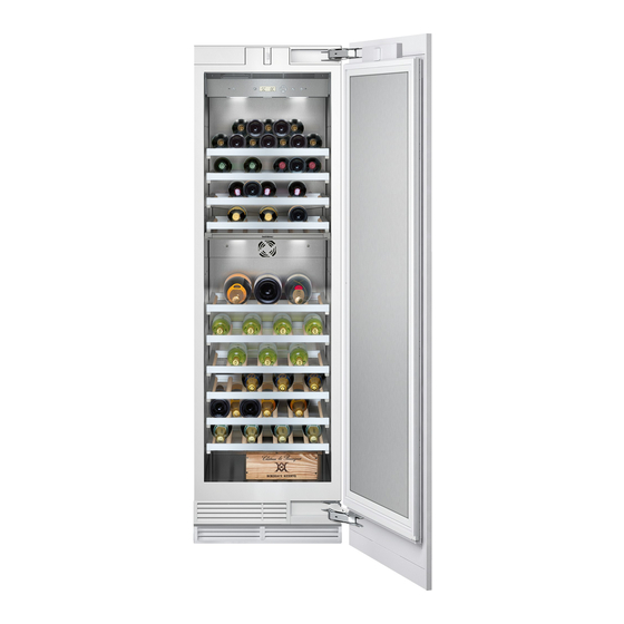
Attaching covering strips By moving by hand align the ice and water dispenser exactly lateral and in the higth to ensure that the gap is exactly the same all the way around. (only for the wine storage cabinet) In certain circumstances, if the frame width is narrow, the side of the covering strip has to be shortened. -
Page 34: Setting The Door Opening Angle
Setting the door opening angle Cut the covering strips of the shortest sides to the required length. According to the set up conditions, it may be necessary to limit the door opening angle. A door opening angle of 115° is set at the factory. To set the door opening angle to 90°: Open the door to 90°. - Page 36 Gaggenau Hausgeräte GmbH Carl-Wery-Straße 34 D-81739 München www.gaggenau.com 9000 920 721 Subject to alterations. en (9308)
Need help?
Do you have a question about the RW 464 and is the answer not in the manual?
Questions and answers