Table of Contents
Advertisement
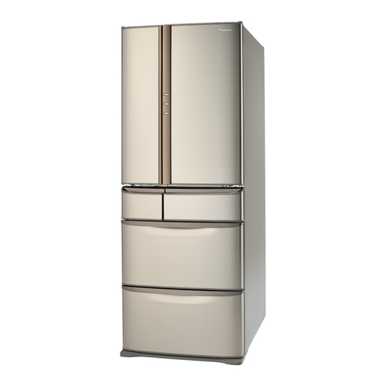
NR-F532TX
Model No.
NR-F532TT
Product Color : -S(Rose stainless) -X(Brown stainless)
Destination
: Hong kong (NR-F532TX / TT)
Destination
: Singapore / Malaysia (NR-F532TX)
© 2008 Matsushita Electric Industrial Co., Ltd. All
rights reserved. Unauthorized copying and distribu-
tion is a violation of law.
Order Number REFD0807002CE
REFRIGERATOR
Advertisement
Table of Contents


Need help?
Do you have a question about the NR-F532TT and is the answer not in the manual?
Questions and answers