Table of Contents
Advertisement
Quick Links
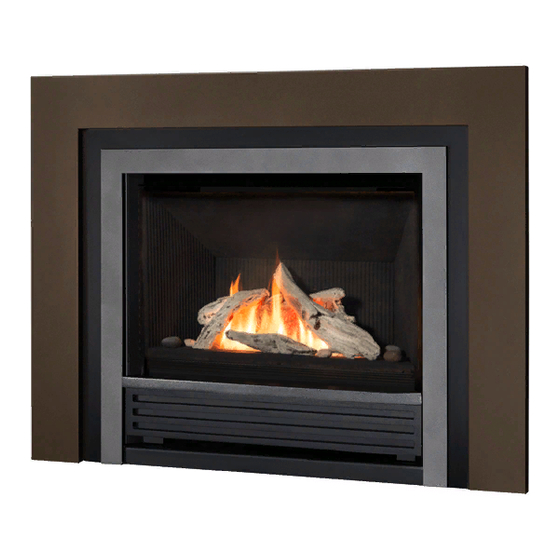
INSTALLER AND OWNER GUIDE
Model 756
INSET LIVE FUEL EFFECT GAS FIRE
Fitted with one of the following fascia.
Denver, Exquisite,
Madison
(GC No. 32-811-46)
We trust that this guide gives
sufficient details to enable this
appliance to be installed and
maintained satisfactorily. However, if
further information is required, our
Valor Fires Technical Helpline will
be pleased to help.
Telephone 0844 8711 565 (National
call rates apply in the United
Kingdom).
In the Republic of Ireland
Telephone 0044 844 8711 565.
INSTALLER: Please leave this guide with the owner
©
Baxi Heating U.K. Limited 2010.
Splendour.
or
5132685/02
Advertisement
Table of Contents

Subscribe to Our Youtube Channel
Related Manuals for Valor Fires 756


Summary of Contents for Valor Fires 756
- Page 1 However, if further information is required, our Valor Fires Technical Helpline will be pleased to help. Telephone 0844 8711 565 (National call rates apply in the United Kingdom).
- Page 2 Warning: Any person who does any unauthorised act in relation to a copyright work may be liable to criminal prosecution and civil claims for damages. Valor Fires, Erdington, Birmingham B24 9QP www.firesandstoves.co.uk Because our policy is one of constant development and improvement, details may vary slightly from those given in this publication ©...
- Page 3 BS EN ISO 9001 quality system accepted by the British Standards Institute. The Highest Standards Valor Fires is a member of SBGI and HHIC (Heating and Hot water Industry Council) that work to ensure high standards of safety, quality and performance. Careful Installation...
-
Page 4: Installer Guide
INSTALLER GUIDE INSTALLER GUIDE FOR OWNER GUIDE SEE PAGES 36 TO 47 © Baxi Heating U.K. Limited 2010. Page 4... -
Page 5: Table Of Contents
INSTALLER GUIDE CONTENTS Section Heading Page INSTALLER GUIDE 4 - 35 OWNER GUIDE 36 - 47 1. SAFETY AND UNPACKING 2. ACCESSORY LIST 3. APPLIANCE DATA AND EFFICIENCY 3.1 General information. 3.2 Efficiency. 4. GENERAL INSTALLATION REQUIREMENTS 4.1 Regulations, Standards and Law. 4.2 Ventilation requirements. - Page 6 INSTALLER GUIDE CONTENTS (Continued) Section Heading Page 11. BURNER & SUPPLY PIPE INSTALLATION 11.1 Fitting the burner. 11.2 Supply pipe installation. 11.3 Preliminary burner checks. 11.3.1 Lighting the fire. 11.3.2 Operating the burner. 11.4 Check inlet pressure. 12. FASCIA INSTALLATION 12.1 Fitting the fascia.
-
Page 7: Safety And Unpacking
INSTALLER GUIDE 1. SAFETY AND UNPACKING Installer Before continuing any further with the installation of this appliance please read the following guide to manual handling: The approximate lifting weight (kg) of this appliance is as below: Model Hotbox Heat engine Fascia Total Denver... -
Page 8: Accessory List
3.2 Efficiency. The efficiency of this appliance has been measured as specified in BS 7977 - 1 and the result is as below: Model Efficiency % (Gross) 756 when converted to LPG. © Baxi Heating U.K. Limited 2010. Page 8... -
Page 9: General Installation Requirements
INSTALLER GUIDE The gross calorific value of the fuel has been used for this efficiency calculation. The test data from which it has been calculated has been certified by Advantica Certification services (0087). The efficiency value may be used in the UK Government's Standard Assessment Procedure (SAP) for energy rating of dwellings. -
Page 10: Ventilation Requirements
INSTALLER GUIDE In Scotland, the current edition of the Building Standards (Scotland) Regulations issued by the Scottish Executive. In Northern Ireland, the current edition of the Building regulations (Northern Ireland) issued by the Department of the Environment for Northern Ireland. In the Republic of Ireland the installation must be carried out by a competent person and also conform to the relevant parts of: a) The current edition of IS 813 “Domestic Gas Installations”... -
Page 11: Chimney Preparation
INSTALLER GUIDE 4.6 Chimney preparation. 4.6.1 If the appliance is intended to be installed to a chimney that was previously used for solid fuel, the flue must be swept clean prior to installation. All flues should be inspected for soundness and freedom from blockages. 4.6.2 Any chimney damper or restrictor should be removed. -
Page 12: The Hearth
INSTALLER GUIDE 4.8 The hearth. The appliance must be mounted behind a non-combustible hearth unless the conditions of section 3.10.1.1 are met (N.B. conglomerate marble hearths are considered as non-combustible). The appliance can be fitted to a purpose made proprietary class “O”-100°C surround. The hearth material must be at least 12mm thick. - Page 13 INSTALLER GUIDE Figure 3. Appliance dimensions and clearances © Baxi Heating U.K. Limited 2010. Page 13...
-
Page 14: Installation Options
INSTALLER GUIDE 4.10 Installation options. In the United Kingdom, as supplied, the appliance can be installed in the following situations: - 4.10.1 Conventional fireplace and hearth. To a fireplace complete with surround and hearth as shown in figure 4 and complying with BS1251 after removal of the fireback and sufficient material behind the fireback for a debris catchment space. -
Page 15: Hole-In-The-Wall' Installations
INSTALLER GUIDE 4.10.1.1 ‘Hole-in-the-wall’ Installations. It is recommended that a hearth should be installed as in figure 4. If a hearth is not fitted, the fire must be installed so that the distance from the base of the fireplace opening in the wall to the finished floor level is at least 25mm. Where there is no floor covering or carpet and the floor is of a type that is likely to be covered in such a way then the distance from the base of the fireplace opening in the wall to the finished floor level should be increased to at least 100mm. -
Page 16: Precast Concrete Or Clay Flue Block System And Hearth
INSTALLER GUIDE 4.10.3 Precast concrete or clay flue block system and hearth. The appliance can be installed to a precast concrete or clay flue block system conforming to BS EN 1858 with dimensions as in figure 7. BS 1289 part 1 recommends there should be an air space or insulation between the flue blocks and the plaster because heat transfer may... -
Page 17: Propane Gas Fires
INSTALLER GUIDE 2. The flue must conform to BS 5440: Part 1 in design and installation. The flue, measured from the bottom of the fireplace opening to the bottom of the terminal, shall be not less than 3m in actual vertical height. When calculated in accordance with BS 5440: Part 1 Annex A, the minimum equivalent height of the flue shall be 2.0m of 125mm dia. -
Page 18: Pack Contents
INSTALLER GUIDE 5. PACK CONTENTS Length of foam seal. Burner and hotbox unit. Fibre plugs. Spacing frame (Three separate pieces). Woodscrews. Edge clips for securing the spacing frame. Fire retaining cables. Inlet ‘T’ Connector which includes a nut Cable clamps. and olive for 8mm inlet pipe. -
Page 19: Fireplace Check
INSTALLER GUIDE 6. FIREPLACE CHECK 6.1 Soundness for appliance attachment. A primary method of retaining the appliance is provided. This involves using concealed tension cables fixed to the rear of the fireplace opening together with secondary fixing to the fireplace floor. This method is detailed in section 10 of this manual. -
Page 20: Gas Supply Connection
INSTALLER GUIDE 8. GAS SUPPLY CONNECTION A nut and olive are provided for an 8mm pipe inlet connection to the ‘T’ connector at the bottom front of the appliance. The ‘T’ connector can be rotated to allow a connection from any rear-concealed connection. The ‘T’ connector includes a valve for isolating the gas supply and a pressure test point. - Page 21 INSTALLER GUIDE 4. Fit the two “U” section seals to the bottom edges of the hotbox side flanges (See figure 11). 5. It is important that the grommet supplied in the loose parts pack is fitted to the hole in the rear of the hotbox.
- Page 22 INSTALLER GUIDE 9. Supplied with the fire are short and long lengths of self adhesive foam seal. Take the short length, peal off the adhesive backing and stick it to the underside of the hotbox (See figure 14). 10. Supplied with the fire is a spacing frame. This is made up of three separate pieces, a top and two sides.
- Page 23 INSTALLER GUIDE 12. The long length of self adhesive foam seal supplied with the fire will need to be fitted to the outer rear edges of the side and top pieces of the spacer frame. Ensure that there is no gap between the foam seals where they meet at the top flange (See figure 17).
-
Page 24: Hotbox Installation
INSTALLER GUIDE 10. HOTBOX INSTALLATION 10.1 Cable retention and floor fixing. 1. Make sure that the relevant areas at the fireplace back or floor are sound enough to take the eyebolts and screws. If these areas have deteriorated due to prolonged use they should be made sound with suitable cement. - Page 25 INSTALLER GUIDE 6. Thread the cables through the eyebolts. Return the cables through the holes near the bottom of the hotbox back panel (See figure 21) (For precast or clay block flue systems return the cables through the slotted holes in the side of the hotbox). 7.
-
Page 26: Sealing Floor Front - All Installations
INSTALLER GUIDE 14. Feed the free length of the cables into the gap between the inner and outer back panels so that they are available to allow easy removal and refitting of the appliance during subsequent service calls. Do not cut off the free lengths of cable. On precast flue installations feed the cables into the small holes at the base of the side panels. -
Page 27: Preliminary Burner Checks
INSTALLER GUIDE 11.3 Preliminary burner checks. Some burner operations can be checked at this stage. Checking now will mean that less disassembly will be required if any problems are found. A full check should still be made, however, after final installation. 11.3.1 Lighting the fire. -
Page 28: Fascia Installation
INSTALLER GUIDE 12. FASCIA INSTALLATION 12.1 Fitting the fascia. 1. Unpack the fascia. Carefully lift the fascia. Place the fascia against the fireplace front surface so that the four hooked brackets at the back of the fascia are directly above the four retaining brackets of the hotbox. -
Page 29: Full Operating Checks
INSTALLER GUIDE 13. FULL OPERATING CHECKS 13.1 Check the burner operation. Repeat the checks conducted in section 11.3.1 and 11.3.2. Please note: When first turned on from cold, the flames will appear predominantly blue. When operating the fire for the first time, some vapours may be given off which could set off smoke alarms in the vicinity. -
Page 30: Flame Supervision And Spillage Monitoring System
INSTALLER GUIDE not satisfactory disconnect the appliance and advise the customer of the cause of failure. 13.3 Flame supervision and spillage monitoring system. This pilot unit includes a system that will automatically shut off the gas supply if the pilot flame goes out or if there is insufficient oxygen due to spillage or poor ventilation. This monitoring system must not be adjusted, bypassed or put out of operation. -
Page 31: Servicing & Parts Replacement
INSTALLER GUIDE 9. Advise that the fire may give off a slight odour while new. This is quite normal and it will disappear after a short period of use. 10. Inform the customer that the Serial number for the appliance is located on the information label located behind the lower cover and attached underneath the burner assembly. -
Page 32: To Remove The Fascia
INSTALLER GUIDE 15.1 To remove the fascia. 1. There is a heat baffle that is screwed to the fascia and spillage plate (See section 12.2 and figure 27). Unscrew and remove this heat baffle. 2. The fascia is held in place by four hooked brackets at the back of the fascia. -
Page 33: To Remove The Spillage Plate
INSTALLER GUIDE 15.3 To remove the spillage plate. 1. Remove the fascia as in section 15.1. 2. Detach the spillage plate from the hotbox by removing the four screws (See figure 31). 3. Replace in the reverse order. 15.4 To remove the inner panel. 1. -
Page 34: To Remove The Gas Valve
INSTALLER GUIDE 15.6 To remove the gas valve. (See figure 34). 1. Remove the burner unit (See section 15.2). 2. If turning the burner upside down, ensure that the work surface is suitably protected. This will avoid damage to the work surface. -
Page 35: To Replace The Top Surface Of The Burner
INSTALLER GUIDE 15.9 To replace the top surface of the burner. 1. Lift and remove the elliptical burner cover from the burner surface. 2. The top surface of the burner is secured using eight screws. The screws have a non-stick coating and should be easy to remove. However, it is advisable to spray a small amount of releasing oil on to the screws and leave them for a few minutes before attempting to remove. -
Page 36: Owner Guide
OWNER GUIDE OWNER GUIDE FOR WARRANTY AND SERVICE INFORMATION SEE PAGES 44 TO 47 © Baxi Heating U.K. Limited 2010. Page 36... - Page 37 OWNER GUIDE LIST OF CONTENTS Section Page SAFETY APPLIANCE DIMENSIONS GAS CONSUMPTION OPERATING YOUR FIRE The Oxysafe flame sensing and flue blockage safety system. To light the fire. Lighting with a taper. To turn off. CLEANING YOUR FIRE Metal and painted parts. Burner top surface.
- Page 38 OWNER GUIDE SAFETY IF YOU SMELL GAS DON’T SMOKE. EXTINGUISH ALL NAKED FLAMES. DON’T TURN ELECTRICAL SWITCHES ON OR OFF. TURN OFF THE GAS SUPPLY AT THE METER OR TANK AS APPROPRIATE. OPEN DOORS AND WINDOWS TO GET RID OF THE GAS. IMMEDIATELY CALL THE GAS EMERGENCY SERVICE FROM A NEIGHBOURS PHONE - SEE YOUR LOCAL TELEPHONE DIRECTORY.
- Page 39 OWNER GUIDE Do get advice about the suitability of any wall covering near your fire. Soft wall coverings (e.g. embossed vinyl, etc.) which have a raised pattern are easily affected by heat. They may, therefore, scorch or become discoloured when close to a heating appliance.
- Page 40 OWNER GUIDE GAS CONSUMPTION Natural Gas Has a maximum natural gas input of 5.3kW (Gross) Has a maximum natural gas output of 2.45kW Has a minimum natural gas input of 3.2kW (Gross) Has a minimum natural gas output of 1.5kW Has a maximum LPG input of 5.3kW (Gross) Has a maximum LPG gas output of 2.45kW Has a minimum LPG gas input of 4.3kW (Gross)
- Page 41 OWNER GUIDE To light the fire. To gain access to the control knob lower the bottom front cover. To do this, gently push and release the top of the front cover with the fingertips. The magnetic catch will release the front cover (See figure 3).
- Page 42 OWNER GUIDE Lighting with a taper. (See figure 5). In the unlikely event of failure of the ignition spark, the pilot can be lit by a taper or long spill. Hold the taper or spill over the pilot. Depress the control knob, turn it to PILOT/IGN position and depress.
- Page 43 OWNER GUIDE MAINTENANCE Regular maintenance. In order to achieve and maintain high levels of personal safety and performance efficiency, it is essential that the opening at the back of the fire and the flue are kept clear of any form of obstruction. It is possible that deposits of mortar or soot could fall and accumulate causing the flue to be blocked or restricted and so preventing proper clearance of dangerous exhaust fumes.
- Page 44 OWNER GUIDE WARRANTY AND SERVICE Standard Warranty Terms & Conditions The warranty is for 12 months subject to contract. In the United Kingdom servicing can be carried out either by a heateam service engineer or a GAS SAFE REGISTER engineer. Outside of the United Kingdom servicing can be carried out either by a CORGI or GAS SAFE REGISTER engineer.
- Page 45 OWNER GUIDE When calling heateam, it would be helpful if you could have the following information to hand:- Fire serial number and fascia code (Located on the information label - See figure 6 on page 47)*. Date of installation*. Your installer name and address details*. Fire make and model number*.
- Page 46 OWNER GUIDE Installer Details (Block Capitals) Installer Name Gas Safe Register or Corgi Registration Number. Company Name. Company Address Company Telephone number Company Fax number © Baxi Heating U.K. Limited 2010. Page 46...
-
Page 47: Owner Guide
OWNER GUIDE Model Serial number (Can be found on the information label - See figure 6) A LABEL CONTAINING THE SERIAL NUMBER MAY HAVE BEEN PLACED INSIDE THIS BOX. Fascia name (Block Capitals) Fascia code - Can be found close to the information label (Block Capitals) A LABEL CONTAINING THE FASCIA CODE MAY HAVE BEEN... - Page 48 © Baxi Heating U.K. Limited 2010.
Need help?
Do you have a question about the 756 and is the answer not in the manual?
Questions and answers