Table of Contents
Advertisement
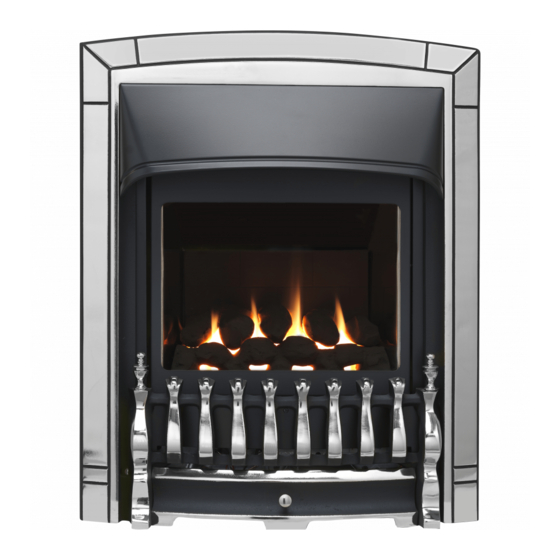
INSTALLER AND OWNER GUIDE
Model 541
ROOM SEALED RADIANT / CONVECTOR
GAS FIRE
Fitted with one of the following fascia.
Chic, Decadent
Dream
(GC No. 32-032-65)
We trust that this guide gives
sufficient details to enable this
appliance to be installed and
maintained satisfactorily. However, if
further information is required, our
Valor Fires Technical Helpline will
be pleased to help.
Telephone 0844 8711 565 (National
call rates apply in the United
Kingdom).
In the Republic of Ireland
Telephone 0044 844 8711 565.
INSTALLER: Please leave this guide with the
©
Baxi Heating U.K. Limited 2009.
or
5133673/02
owner
Advertisement
Table of Contents

Subscribe to Our Youtube Channel
Related Manuals for Valor Fires 541 Chic


Summary of Contents for Valor Fires 541 Chic
- Page 1 However, if further information is required, our Valor Fires Technical Helpline will be pleased to help. Telephone 0844 8711 565 (National call rates apply in the United Kingdom).
- Page 2 Warning: Any person who does any unauthorised act in relation to a copyright work may be liable to criminal prosecution and civil claims for damages. Valor Fires, Erdington, Birmingham B24 9QP www.firesandstoves.co.uk Because our policy is one of constant development and improvement, details may vary slightly from those given in this publication ©...
- Page 3 BS EN ISO 9001 quality system accepted by the British Standards Institute. The Highest Standards Valor Fires is a member of SBGI and HHIC (Heating and Hot water Industry Council) that work to ensure high standards of safety, quality and performance. Careful Installation...
- Page 4 INSTALLER GUIDE INSTALLER GUIDE FOR OWNER GUIDE SEE PAGES 46 TO 55 © Baxi Heating U.K. Limited 2009. Page 4...
-
Page 5: Table Of Contents
INSTALLER GUIDE CONTENTS Section Heading Page INSTALLER GUIDE 4 - 45 OWNER GUIDE 46 - 55 1. SAFETY 2. APPLIANCE DATA AND EFFICIENCY. 2.1 General information. 2.2 Efficiency. 3. LIST OF AVAILABLE KITS 4. APPLIANCE AND RECESS DIMENSIONS 5. GENERAL INSTALLATION REQUIREMENTS 5.1 Regulations, Standards and Law. -
Page 6: Installer Guide
INSTALLER GUIDE CONTENTS (Continued) Section Heading Page 9. FLUE TERMINAL INSTALLATION 9.1 Cutting flue to size. 9.2 Fitting to wall. 9.3 Fitting the terminal guard. 10. GAS CONNECTION 11. CERAMIC COALS INSTALLATION 12. CERAMIC PEBBLES INSTALLATION 13. WINDOW FITTING 14. FULL OPERATING CHECKS 14.1 Check for leaks. -
Page 7: Safety
INSTALLER GUIDE 1. SAFETY Installer Before continuing any further with the installation of this appliance please read the following guide to manual handling: The lifting weight (kg) of this appliance is as below: Model Heat Engine Fascia / Fire front Combined Weight Decadent 12.58... -
Page 8: Appliance Data And Efficiency
INSTALLER GUIDE 2. APPLIANCE DATA AND EFFICIENCY. 2.1 General information. Under no circumstances is this fire to be converted to LPG. An LPG conversion kit does not exist for this gas fire. Natural Inlet pressure 20mbar Input - Max. (Gross) 3.65kW (12,454 Btu/h) Input - Min. -
Page 9: Efficiency
INSTALLER GUIDE 2.2 Efficiency. The efficiency of this appliance has been measured as specified in BS EN 613 and the result is as below: Model Efficiency % (Gross) The gross calorific value of the fuel has been used for this efficiency calculation. The test data from which it has been calculated has been certified by Advantica Certification services (0087). -
Page 10: Appliance And Recess Dimensions
INSTALLER GUIDE 4. APPLIANCE AND RECESS DIMENSIONS This appliance must not be recessed into a combustible wall. See Figure 4. Model Description Chic Decadent Dream Appliance height (mm) Appliance width (mm) Appliance depth into room (mm) Minimum mandatory clearance to combustible surfaces projecting beyond the front of appliance (mm). -
Page 11: General Installation Requirements
INSTALLER GUIDE Figure 2. Recess and flue hole dimensions. 5. GENERAL INSTALLATION REQUIREMENTS 5.1 Regulations, Standards and Law. The installation must be in accordance with this guide. For the user’s protection, in the United Kingdom it is the law that all gas appliances are installed by competent persons in accordance with the current edition of the Gas Safety (Installation and Use) Regulations. -
Page 12: Considerations For Timber Framed Buildings
INSTALLER GUIDE Where no specific instructions are given, reference should be made to the relevant British Standard Code of Practice. 5.1.1 Considerations for timber framed buildings. Installation to a timber-framed building should be in accordance with the relevant sections of The Institute of Gas Engineers publication IGE/UP/7 “Gas installations in timber frame buildings”. -
Page 13: The Surround
INSTALLER GUIDE 5.5.3 Combustible cladding. Decadent and Dream model. If the fire is to be fitted against a wall with combustible cladding, the cladding must be removed from the area shown in figure 3. Chic model. If the fire is to be fitted against a wall with combustible cladding, the cladding must be removed from behind the fire and must have a minimum clearance of 5mm from the fascia /... -
Page 14: Fireplace Clearances
INSTALLER GUIDE 5.8 Fireplace clearances. 5.8.1 The minimum height from the base of the fire to the underside of any shelf made from wood or other combustible materials is as follows:- • For a shelf up to 150mm deep Minimum height = 780mm. •... -
Page 15: Installation Options
INSTALLER GUIDE 5.9 Installation options. 5.9.1 The appliance can be installed into the following: A minimum 4.5 inch rebate surround or 5 inch spacer kit Part No 0595121. Where either of these are mounted to a combustible wall make sure that there is no combustible material or combustible cladding in the area indicated on the wall fixing template. - Page 16 INSTALLER GUIDE Minimum Terminal position distance (mm) Directly below an opening, air brick, opening window etc. 300mm Above an opening, air brick, opening window etc. 300mm Horizontally to an opening, air brick, opening window etc. 300mm Below gutters, soil pipes or drain pipes. 300mm Below eaves.
-
Page 17: Unpacking And Preliminary Checks
INSTALLER GUIDE Figure 6. 6. UNPACKING AND PRELIMINARY CHECKS 6.1 Unpacking. 1 Main fire assembly. 1 Controls heat baffle (Chic) 1 Fascia (Attached to fire). 3 Edge clips for controls heat 1 Ceramic fuel effect (Packed in the fire). baffle 1 Nut &... -
Page 18: Appliance Disassembly
INSTALLER GUIDE 6.2 Appliance disassembly. 6.2.1 Fascia removal on the Decadent and Dream models (See figure 7). Remove the two screws securing the bottom of the fascia to the sides of the convection box. Raise the fascia to allow the retaining lugs at the top to clear the slots in the convection box hood and then lift clear. -
Page 19: Preliminary Checks
INSTALLER GUIDE 6.2.3 Window and ceramic fuel effect removal (All models). Unscrew and remove the three spring loaded window fixing screws and bushess from the base of the window frame (See figure 9). Keep the screws and bushess in a safe place. Gently swing the base of the window frame forward while lifting the frame upward. -
Page 20: Gas Supply Connection
INSTALLER GUIDE 6.3.2 Check flame control motor. (See figure 11) Lift the plastic battery holder out of its metal support situated at the lower right corner. Fit the four 1.5V batteries and replace the battery holder. Place the fascia in front of the fire and connect the battery and motor leads. -
Page 21: Wall Preparation
INSTALLER GUIDE 8. WALL PREPARATION 8.1 Select appliance position. The flue must be installed so that it is at right angles to the back panel of the fire all round the flue circumference. For timber framed buildings make sure that the flue opening will be between studs. When being recessed into a non-combustible wall or builders opening the fire itself should be fitted vertically against a flat wall. -
Page 22: Preparing A Wall Cavity
INSTALLER GUIDE Make the opening below the lintel by removing the masonry and clearing debris. If the cavity has loose fill (e.g. granular) insulation material, pack the edges of the opening with Rockwool as you proceed to hold back the insulating material. 8.2.2 Preparing a wall cavity. -
Page 23: Cutting The Flue Hole For Brick, Stone Etc. Building
INSTALLER GUIDE 8.4 Cutting the flue hole for brick, stone etc. building. Cut the hole for the flue unit. Make sure that it is straight and level. Though a hammer and chisel can be used, using a core drill is by far the quickest and simplest method for normal brick work. - Page 24 INSTALLER GUIDE vapour control layer (VCL), if possible, cut the hole approximately 10mm undersize so that the sleeve will be forced through the layer. A recommended technique for cutting the inner leaf is shown in figure 14. Fit the non-combustible sleeve to the inner leaf. The sleeve must extend to be at least flush with the breather membrane / timber sheathing but must not protrude more than 10mm into the cavity.
-
Page 25: Prepare Appliance Fixing Holes
INSTALLER GUIDE 8.6 Prepare appliance fixing holes. 8.6.1 Screwing case to wall. Recheck the position of the screw fixing holes relative to the flue hole. Drill the four fixing holes to a minimum depth of 42mm using a suitably sized masonry drill for the wall plugs supplied. - Page 26 INSTALLER GUIDE Figure 16. Flue unit installation - Brick etc. building Figure 17. Flue unit installation - Timber framed building. © Baxi Heating U.K. Limited 2009. Page 26...
-
Page 27: Fitting To Wall
INSTALLER GUIDE 9.2 Fitting to wall. Fit the flue tubes firmly over the spigots at the rear of the fire. Make sure that the seam on the flue tube is not at the bottom. Push on until the outer (air) tube just covers the slots in the appliance outer spigot (See figure 18). -
Page 28: Fitting The Terminal Guard
INSTALLER GUIDE 9.3 Fitting the terminal guard. Fold the terminal guard as shown in figure 19. Place the guard centrally over the flue terminal. Holding the guard in position and using it as a template, mark on the wall the positions of the four fixing holes. -
Page 29: Ceramic Coals Installation
INSTALLER GUIDE 11. CERAMIC COALS INSTALLATION This section is for models supplied with a ‘Coal’ fuel effect only. For ‘Pebble fuel effect’ see section 12 11.1 Ceramic coal fuel effect installation for the Decadent and Dream models. The ceramic fuel effect may cause staining / discolouration to decorative surfaces. It is therefore advisable to protect decorative surfaces. - Page 30 INSTALLER GUIDE 3. Hold coal ‘B’ upright with the arrow pointing to the top. Locate coal ‘B’ as shown in figure 22. Figure 22. 4. Hold coal ‘C’ upright with the arrow pointing to the top. Locate coal ‘C’ as shown in figure 23.
-
Page 31: Ceramic Pebbles Installation
INSTALLER GUIDE 12. CERAMIC PEBBLES INSTALLATION This section is for models supplied with a ‘Pebble’ fuel effect only. For ‘Coal fuel effect’ see section 11. 12.1 Ceramic Pebble fuel effect installation for Chic model. The ceramic fuel effect may cause staining / discolouration to decorative surfaces. - Page 32 INSTALLER GUIDE 3. Hold pebble ‘B’ upright with the arrow pointing to the top. Locate pebble ‘B’ as shown in figure 28. Figure 28. 4. Hold pebble ‘C’ upright with the arrow pointing to the top. Locate pebble ‘C’ as shown in figure 29.
-
Page 33: Window Fitting
INSTALLER GUIDE 13. WINDOW FITTING Fitting the window. Locate the channel at the top of the window over the top of the firebox opening. Refit the three spring loaded screws and bushes. The wide part of the bushes should be in contact with the widow frame. Tighten sufficiently to seal the firebox. Pull the bottom of the window forward and release to check that the window opens slightly and returns in the event of a delayed ignition explosion. -
Page 34: Checking Inlet Pressure
INSTALLER GUIDE seconds to allow the pilot flame to stabilise then release it. If the pilot does not remain alight ensure that the air has been purged. Partially depress the right control knob and turn to the main burner position marked The left-hand knob is for burner flame adjustment. -
Page 35: Fascia Fitting
INSTALLER GUIDE 15. FASCIA FITTING If you have not done so already complete the information on the last pages of this guide. 15.1 Fitting the Decadent fascia Remove any protective film from the fascia. Locate the two lugs at the top of the fascia in the slots in the convection box hood. -
Page 36: Fitting The Chic Fascia
INSTALLER GUIDE 15.2 Fitting the Chic fascia. Supplied with the fire is a controls heat baffle and three edge clips. These must be fitted to the heat engine before fitting the Chic fascia. Locate and secure the baffle as in figure 38. Remove any protective film from the fascia. -
Page 37: Fitting The Dream Fascia
INSTALLER GUIDE Supplied in the fascia pack are two tubular trim sets. Hang these to the tabs on the fascia (See figure 41). Figure 41. Fitting the ‘Chic’ hanging trims The lower section of the fascia is secured with magnets. Locate it as in figure 42. The bottom of the lower section should sit on the tags as shown. -
Page 38: Final Review
INSTALLER GUIDE 16. FINAL REVIEW 1. COMPLETE THE INFORMATION IN THE WARRANTY AND SERVICE SECTION OF THE OWNER GUIDE (See last pages of the OWNER guide). 2. Recheck the pilot ignition and operation of the fire through the range of settings. 3. -
Page 39: Servicing & Parts Replacement
INSTALLER GUIDE 17. SERVICING & PARTS REPLACEMENT Always turn off the gas and allow the appliance to cool completely before commencing any servicing (The inlet ‘T’ connector on this appliance incorporates an isolating valve). Always test for gas soundness after refitting the appliance. This product uses a fuel effect, a burner compartment rear wall and gaskets containing Refractory Ceramic Fibres (RCF), which are man-made vitreous silicate fibres. - Page 40 INSTALLER GUIDE Chic The lower section of the fascia is secured with magnets. Remove this by pulling clear of the fascia (See figure 44). Remove the two tubular trim sets from the top and bottom of the fascia. To do this simply lift upward and forward (See figure 45).
-
Page 41: To Remove Or Clean The Window Unit
INSTALLER GUIDE Unscrew and remove the two screws that secure the bottom of the fascia sides to the convection box (See figure 47). Remove the wiring loom connectors from the left hand side of the gas valve. Raise the fascia to allow the retaining lugs at the top to clear the slots in the convection box hood and then lift clear (See figure 47). -
Page 42: To Remove The Ceramic Fuel Effect And Rear Wall
INSTALLER GUIDE should be against the window frame. Tighten sufficiently to seal to the firebox. Replace the fascia and castings. 17.3 To remove the ceramic fuel effect and rear wall. Remove the fascia (See section 17.1). Remove the window unit (See section 17.2) Lift out the ceramic fuel effect. -
Page 43: To Remove The Burner From The Burner Module
INSTALLER GUIDE will only fit to the correct motor terminals. 17.6 To remove the burner from the burner module. Remove the complete burner module as in section 17.5 Support the injector elbow and unscrew the pipe nut from its base. The burner bracket is secured to the front cover by four screws. -
Page 44: To Remove The Gas Valve
INSTALLER GUIDE Unscrew the two screws securing the pilot to the module front. If the pilot gasket is damaged in any way it must be replaced. Replace in reverse order. When replacing, make sure that the wiring loom runs above and to the right of the battery box and behind the control valve (See figure 55). - Page 45 INSTALLER GUIDE Press firmly inward the two retaining claws on the inside of the rocker switch. Remove the loom through the switch aperture in the case side. Replace in the reverse order. When replacing the switch make sure that the white printing on the switch side faces the back of the fire.
-
Page 46: Owner Guide
OWNER GUIDE OWNER GUIDE FOR WARRANTY AND SERVICE INFORMATION SEE PAGES 53 TO 55 © Baxi Heating U.K. Limited 2009. Page 46... - Page 47 OWNER GUIDE CONTENTS Heading Page SAFETY GAS CONSUMPTION APPLIANCE DIMENSIONS OPERATING YOUR FIRE To light the pilot. To light the main burner. To turn off the main burner only. To turn off the main burner and pilot. SERVICING AND MAINTENANCE Battery replacement.
- Page 48 OWNER GUIDE SAFETY IF YOU SMELL GAS DON’T SMOKE. EXTINGUISH ALL NAKED FLAMES. DON’T TURN ELECTRICAL SWITCHES ON OR OFF. TURN OFF THE GAS SUPPLY AT THE METER. OPEN DOORS AND WINDOWS TO GET RID OF THE GAS. IMMEDIATELY CALL THE GAS EMERGENCY SERVICE FROM A NEIGHBOURS PHONE - SEE YOUR LOCAL TELEPHONE DIRECTORY.
- Page 49 OWNER GUIDE become hot. The area above the outlet at the top of the Chic fascia gets hot. It is important that this area is not touched when the fire is on or cooling down. Do wait six minutes before attempting to relight if the fire is switched off or the flames are extinguished for any reason.
- Page 50 OWNER GUIDE APPLIANCE DIMENSIONS See figure 1. Model Description Chic Decadent Dream Appliance height (mm) Appliance width (mm) Appliance depth into room (mm) Minimum mandatory clearance to combustible surfaces projecting beyond the front of appliance (mm). Recommended clearance to non- combustible surfaces for access purposes (mm).
- Page 51 OWNER GUIDE being turned back on until it is safe after it has been turned off. If, for any reason, the fire goes out or if the fire is turned off, always wait at least six minutes before attempting to relight. If the device starts to shut off the gas frequently, get expert advice.
- Page 52 OWNER GUIDE To turn off the main burner and pilot. Turn the right hand control knob to the pilot position marked . Push the • knob in at this position and turn to the off position marked CLEANING YOUR FIRE Turn the fire off and allow it to cool completely before attempting any cleaning.
- Page 53 OWNER GUIDE WARRANTY AND SERVICE Standard Warranty Terms & Conditions The warranty is for 12 months subject to contract. In the United Kingdom servicing can be carried out either by a heateam service engineer or a GAS SAFE REGISTER engineer. Outside of the United Kingdom servicing can be carried out either by a CORGI or GAS SAFE REGISTER engineer.
- Page 54 OWNER GUIDE What this warranty covers Free of charge repair or replacement of components found to be of faulty manufacture. Free of charge replacement of the complete unit providing the failure is related to a manufacturing fault that cannot be repaired or is uneconomic to repair. What this warranty does not cover Repairs to fires which haven’t been installed and commissioned properly and as set out in the installation instructions.
-
Page 55: Owner Guide
OWNER GUIDE Model Serial number (Can be found on the information label - See figure 6) A LABEL CONTAINING THE SERIAL NUMBER MAY HAVE BEEN PLACED INSIDE THIS BOX. Fascia name (Block Capitals) Fascia code - Can be found close to the information label (Block Capitals) A LABEL CONTAINING THE FASCIA CODE MAY HAVE BEEN PLACED INSIDE THIS... - Page 56 © Baxi Heating U.K. Limited 2009.
Need help?
Do you have a question about the 541 Chic and is the answer not in the manual?
Questions and answers