Table of Contents
Advertisement
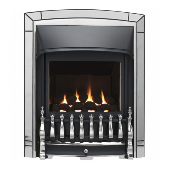
INSTALLER AND OWNER GUIDE
Model 541
ROOM SEALED RADIANT / CONVECTOR
GAS FIRE
Fitted with one of the following fascia.
Camden, Seattle, Sonnet
Ultimate.
(GC No. 32-032-64)
We trust that this guide gives
sufficient details to enable this
appliance to be installed and
maintained satisfactorily. However, if
further information is required, our
Valor Fires Technical Helpline will
be pleased to help.
Telephone 0844 8711 565 (National
call rates apply in the United
Kingdom).
In the Republic of Ireland
Telephone 0044 844 8711 565.
INSTALLER: Please leave this guide with the
©
Baxi Heating U.K. Limited 2010.
5133756/03
or
owner
Advertisement
Table of Contents

Related Manuals for Valor Fires 541


Summary of Contents for Valor Fires 541
- Page 1 However, if further information is required, our Valor Fires Technical Helpline will be pleased to help. Telephone 0844 8711 565 (National call rates apply in the United Kingdom).
- Page 2 Warning: Any person who does any unauthorised act in relation to a copyright work may be liable to criminal prosecution and civil claims for damages. Valor Fires, Erdington, Birmingham B24 9QP www.firesandstoves.co.uk Because our policy is one of constant development and improvement, details may vary slightly from those given in this publication ©...
- Page 3 BS EN ISO 9001 quality system accepted by the British Standards Institute. The Highest Standards Valor Fires is a member of SBGI and HHIC (Heating and Hot water Industry Council) that work to ensure high standards of safety, quality and performance. Careful Installation...
- Page 4 INSTALLER GUIDE INSTALLER GUIDE FOR OWNER GUIDE SEE PAGES 40 TO 51 © Baxi Heating U.K. Limited 2010. Page 4...
-
Page 5: Table Of Contents
INSTALLER GUIDE CONTENTS Section Heading Page INSTALLER GUIDE 4 - 39 OWNER GUIDE 40 - 51 1. SAFETY 2. APPLIANCE DATA AND EFFICIENCY 2.1 General information. 2.2 Efficiency. 3. LIST OF AVAILABLE KITS 4. APPLIANCE AND RECESS DIMENSIONS 5. GENERAL INSTALLATION REQUIREMENTS 5.1 Regulations, Standards and Law. -
Page 6: Installer Guide
INSTALLER GUIDE CONTENTS (Continued) Section Heading Page 9. FLUE AND TERMINAL INSTALLATION 9.1 Cutting flue to size. 9.2 Fitting to wall. 9.3 Fitting the terminal guard. 10. GAS CONNECTION 11. CERAMIC COALS INSTALLATION 12. CERAMIC PEBBLES INSTALLATION 13. WINDOW FITTING 14. -
Page 7: Safety
INSTALLER GUIDE 1. SAFETY Installer Before continuing any further with the installation of this appliance please read the following guide to manual handling: The approximate lifting weight (kg) of this appliance is as below: Model Heat Engine Fascia Fire front Combined Weight inc. -
Page 8: Appliance Data And Efficiency
INSTALLER GUIDE as a stable, non-reactive hazardous waste and may be disposed at a landfill licensed to accept such waste. Protective clothing is not required when handling these articles, but we recommend you follow the normal hygiene rules of not smoking, eating or drinking in the work area and always wash your hands before eating or drinking. -
Page 9: Efficiency
INSTALLER GUIDE 2.2 Efficiency. The efficiency of this appliance has been measured as specified in BS EN 613 and the result is as below: Model Efficiency % (Gross) The gross calorific value of the fuel has been used for this efficiency calculation. The test data from which it has been calculated has been certified by Advantica Certification services (0087). -
Page 10: Appliance And Recess Dimensions
INSTALLER GUIDE 4. APPLIANCE AND RECESS DIMENSIONS This appliance must not be recessed into a combustible wall. See figure 4 Model Description Ultimate & Camden & Sonnet Seattle Appliance height (mm) Appliance width (mm) Appliance depth into room (mm) Minimum mandatory clearance to combustible surfaces projecting beyond the front of appliance (mm). - Page 11 INSTALLER GUIDE Figure 1 (Continued). Figure 2. Recess and flue hole dimensions © Baxi Heating U.K. Limited 2010. Page 11...
-
Page 12: General Installation Requirements
INSTALLER GUIDE 5. GENERAL INSTALLATION REQUIREMENTS 5.1 Regulations, Standards and Law. The installation must be in accordance with this guide. For the user’s protection, in the United Kingdom it is the law that all gas appliances are installed by competent persons in accordance with the current edition of the Gas Safety (Installation and Use) Regulations. -
Page 13: Ventilation Requirements
INSTALLER GUIDE 5.2 Ventilation requirements. No special ventilation bricks or vents are required into the room containing the appliance. 5.3 Fireguard requirements. A fireguard complying with BS 8423 should be fitted for the protection of young children, the elderly, the infirm and pet animals. 5.4 Room considerations. -
Page 14: Hearth / Plinth Requirements
INSTALLER GUIDE 5.7 Hearth / plinth requirements. For installations that are elevated and recessed. Models fitted with a fire front or fire front casting set shall have a hearth / plinth fitted. The minimum depth of the hearth / plinth from the fixing plane of the fire is recommended as below. -
Page 15: Fireplace Clearances
INSTALLER GUIDE 5.8 Fireplace clearances. The minimum height from the base of the fire to the underside of any shelf made from wood or other combustible materials is as follows:- • For a shelf up to 150mm deep Minimum height = 780mm. •... -
Page 16: Installation Options
A 2in rebate surround in conjunction with the Valor Fires 3in. spacer kit Part No 0595131. Where the surround is mounted to a combustible wall make sure that there is no combustible material or combustible cladding in the area indicated on the wall- fixing template. - Page 17 INSTALLER GUIDE Minimum Terminal position distance (mm) Directly below an opening, air brick, opening window etc. 300mm Above an opening, air brick, opening window etc. 300mm Horizontally to an opening, air brick, opening window etc. 300mm Below gutters, soil pipes or drain pipes. 300mm Below eaves.
- Page 18 INSTALLER GUIDE Figure 6. *In addition, the terminal should not be nearer than 300mm to an opening in the building fabric formed for the purpose of accommodating a built-in element such as a window frame or door frame (See figure 5). ** The reference to external corners does not apply to building protrusions not exceeding 450mm, such as disused chimneys on external walls.
-
Page 19: Unpacking And Preliminary Checks
INSTALLER GUIDE 6. UNPACKING AND PRELIMINARY CHECKS 6.1 Unpacking. 1 Main fire assembly with fascia. 1 Ceramic fuel effect (Packed in the fire). 1 Nut & olive for 8mm inlet pipe. 1 Fire front / fire front casting set. 1 Flue unit. 1 Wall fixing template. -
Page 20: Preliminary Checks
INSTALLER GUIDE 6.3 Preliminary checks. Check ignition spark (See figure 9). The pilot burner and electrode unit is at the left front corner of the burner. Push in the right hand control knob and turn anticlockwise through the ignition position marked and up to the pilot position marked A spark should flash across from the pilot electrode to the pilot burner hood. -
Page 21: Wall Preparation
INSTALLER GUIDE 8. WALL PREPARATION 8.1 Select appliance position. The flue must be installed so that it is at right angles to the back panel of the fire all round the flue circumference. For timber framed buildings make sure that the flue opening will be between studs. When being recessed into a non-combustible wall or builders opening the fire itself should be fitted vertically against a flat wall. -
Page 22: Combustible Wall Materials
INSTALLER GUIDE structure above is secure and safe. Make the opening below the lintel by removing the masonry and clearing debris. If the cavity has loose fill (e.g. granular) insulation material, pack the edges of the opening with Rockwool as you proceed to hold back the insulating material. 8.2.2 Preparing a wall cavity. -
Page 23: Cutting The Flue Hole For Brick, Stone Etc. Building
INSTALLER GUIDE section 8.5). Do not permanently fix the insulating sheet to the wall at this stage (See section 9.2). 8.4 Cutting the flue hole for brick, stone etc. building. Cut the hole for the flue unit. Make sure that it is straight and level. Though a hammer and chisel can be used, using a core drill is by far the quickest and simplest method for normal brickwork. -
Page 24: Cutting The Flue Hole In Timber Frame Buildings
INSTALLER GUIDE 8.5 Cutting the flue hole in timber frame buildings. Drill the pilot hole and hole in outer wall as section 8.4. Since the flue will pass through combustible material in the inner leaf of the wall, a non-combustible sleeve 203mm (8in.) diameter will be required round the flue (See figure 12). -
Page 25: Prepare Appliance Fixing Holes
INSTALLER GUIDE 8.6 Prepare appliance fixing holes. 8.6.1 Screwing case to wall. Recheck the position of the screw fixing holes relative to the flue hole. Drill the four fixing holes to a minimum depth of 42mm using a suitably sized masonry drill for the wall plugs supplied. - Page 26 INSTALLER GUIDE Figure 14. Flue unit installation - Brick etc. building Figure 15. Flue unit installation - Timber framed building. © Baxi Heating U.K. Limited 2010. Page 26...
-
Page 27: Fitting To Wall
INSTALLER GUIDE 9.2 Fitting to wall. Fit the flue tubes firmly over the spigots at the rear of the fire. Make sure that the seam on the flue tube is not at the bottom. Push on until the outer (air) tube just covers the slots in the appliance outer spigot (See figure 16). -
Page 28: Fitting The Terminal Guard
INSTALLER GUIDE 9.3 Fitting the terminal guard. Fold the terminal guard as shown in figure 17. Place the guard centrally over the flue terminal. Holding the guard in position and using it as a template, mark on the wall the positions of the four fixing holes. -
Page 29: Ceramic Coals Installation
INSTALLER GUIDE 11. CERAMIC COALS INSTALLATION This section is for models supplied with a ‘Coal’ fuel effect only. For ‘Pebble fuel effect’ see section 12 The ceramic fuel effect may cause staining / discolouration to decorative surfaces. It is therefore advisable to protect decorative surfaces. 1. - Page 30 INSTALLER GUIDE 3. Hold coal ‘B’ upright with the arrow pointing to the top. Locate coal ‘B’ as shown in figure 20. Figure 20. 4. Hold coal ‘C’ upright with the arrow pointing to the top. Locate coal ‘C’ as shown in figure 21.
-
Page 31: Ceramic Pebbles Installation
INSTALLER GUIDE 12. CERAMIC PEBBLES INSTALLATION This section is for models supplied with a ‘Pebble’ fuel effect only. For ‘Coal fuel effect’ see section 11. The ceramic fuel effect may cause staining / discolouration to decorative surfaces. It is therefore advisable to protect decorative surfaces. 1. - Page 32 INSTALLER GUIDE 3. Hold pebble ‘B’ upright with the arrow pointing to the top. Locate pebble ‘B’ as shown in figure 26. Figure 26. 4. Hold pebble ‘C’ upright with the arrow pointing to the top. Locate pebble ‘C’ as shown in figure 27.
-
Page 33: Window Fitting
INSTALLER GUIDE 13. WINDOW FITTING Fitting the window. Locate the channel at the top of the window over the top of the firebox opening. Refit the three spring loaded screws and bushes. The wide part of the bushes should be in contact with the window frame. Tighten sufficiently to seal the firebox. Pull the bottom of the window forward and release to check that the window opens slightly and returns in the event of a delayed ignition explosion. -
Page 34: Checking Inlet Pressure
INSTALLER GUIDE The flame height control does not have to be re-set every time the fire is lit. It can be kept at any position enabling the customer to use the right hand control only to ignite the burner at the set flame height. After checking turn the right hand knob to off. -
Page 35: Fascia Fitting
INSTALLER GUIDE 15. FASCIA FITTING If you have not done so already complete the information on the last pages of this guide. Remove any protective film from the fascia. Locate the two lugs at the top of the fascia in the slots in the convection box hood. -
Page 36: Final Review
INSTALLER GUIDE 16. FINAL REVIEW 1. COMPLETE THE INFORMATION IN THE WARRANTY AND SERVICE SECTION OF THE OWNER GUIDE (See last pages of the OWNER guide). 2. Recheck the pilot ignition and operation of the fire through the range of settings. 3. -
Page 37: Servicing & Parts Replacement
INSTALLER GUIDE 17. SERVICING & PARTS REPLACEMENT Always turn off the gas and allow the appliance to cool completely before commencing any servicing. (The inlet ‘T’ connector on this appliance incorporates an isolating valve) Always test for gas soundness after refitting the appliance. This product uses a fuel effect, a burner compartment rear wall and gaskets containing Refractory Ceramic Fibres (RCF), which are man-made vitreous silicate fibres. -
Page 38: To Remove Window Unit
INSTALLER GUIDE 17.2 To remove window unit. Remove the fascia (See section 17.1). Unscrew and remove the three spring-loaded window- fixing screws and bushes from the base of the window frame (See figure 36). Gently swing the base of the window frame forward while lifting the frame upwards. -
Page 39: To Remove The Injector
INSTALLER GUIDE 17.6 To remove the injector. Remove the complete burner module as in section 17.4 Support the injector elbow and unscrew the pipe nut from its base. The burner bracket is secured to the front cover by four screws. Remove these screws. -
Page 40: Owner Guide
OWNER GUIDE OWNER GUIDE FOR WARRANTY AND SERVICE INFORMATION SEE PAGES 47 TO 51 © Baxi Heating U.K. Limited 2010. Page 40... - Page 41 OWNER GUIDE CONTENTS Section Heading Page SAFETY APPLIANCE DIMENSIONS GAS CONSUMPTION OPERATING YOUR FIRE To light the pilot. To light the main burner. To Turn off the main burner only. To turn off the main burner and pilot. CLEANING YOUR FIRE MAINTENANCE WARRANTY AND SERVICE This gas fire is designed to meet the most stringent quality, performance and safety...
- Page 42 OWNER GUIDE SAFETY IF YOU SMELL GAS DON’T SMOKE. EXTINGUISH ALL NAKED FLAMES. DON’T TURN ELECTRICAL SWITCHES ON OR OFF. TURN OFF THE GAS SUPPLY AT THE METER. OPEN DOORS AND WINDOWS TO GET RID OF THE GAS. IMMEDIATELY CALL THE GAS EMERGENCY SERVICE FROM A NEIGHBOURS PHONE - SEE YOUR LOCAL TELEPHONE DIRECTORY.
- Page 43 OWNER GUIDE applicable standards, it is a heating appliance and certain parts of its surface will become hot. Do wait six minutes before attempting to relight if the fire is switched off or the flames are extinguished for any reason. Your fire is fitted with a safety device which will automatically shut off the gas supply to the fire if, for any reason, the flames go out.
- Page 44 OWNER GUIDE APPLIANCE DIMENSIONS See figure 1 Model Description Ultimate & Camden & Sonnet Seattle Appliance height (mm) Appliance width (mm) Appliance depth into room (mm) Minimum mandatory clearance to combustible surfaces projecting beyond the front of appliance (mm). Recommended clearance to non-combustible surfaces for access purposes (mm).
- Page 45 OWNER GUIDE GAS CONSUMPTION Model 541 Has a maximum natural gas input of 3.65kW (Gross) Has a maximum natural gas output of 2.8kW Has a minimum natural gas input of 1.5kW (Gross) Has a minimum natural gas output of 1.13kW OPERATING YOUR FIRE The pilot may be left alight.
- Page 46 OWNER GUIDE To light the pilot. Push in the right control knob (the pilot lighting knob) and, while keeping it depressed, turn anticlockwise through the ignition position marked and up to the pilot position marked . The spark should light the pilot.
- Page 47 OWNER GUIDE MAINTENANCE Regular maintenance. In order to achieve and maintain high levels of personal safety and performance efficiency it is essential that the flue terminal outside the building is kept clear of any form of obstruction. We recommend that all gas appliances and their flues are checked annually by a competent person (In the UK a GAS SAFE REGISTER engineer, Outside of the UK a CORGI or GAS SAFE REGISTER engineer).
- Page 48 OWNER GUIDE to Friday 8am – 6pm, weekends and Bank Holidays 8.30am – 2pm, excluding Christmas Day and New Years day. When calling heateam, it would be helpful if you could have the following information to hand:- Fire serial number and fascia code (Located on the information label - See figure 5 on page 50)*.
- Page 49 OWNER GUIDE © Baxi Heating U.K. Limited 2010. Page 49...
- Page 50 OWNER GUIDE To be completed by Installer: Installer Details (Block Capitals) Installer Name Gas Safe Register or Corgi Registration Number. Company Name. Company Address Company Telephone number Company Fax number Figure 5. © Baxi Heating U.K. Limited 2010. Page 50...
-
Page 51: Owner Guide
OWNER GUIDE Model Serial number (Can be found on the information label - See figure 5) A LABEL CONTAINING THE SERIAL NUMBER LABEL SERIAL NUMBER MAY HAVE TO BE AFFIXED HERE BEEN PLACED INSIDE THIS BOX. Fascia name (Block Capitals) Fascia code - Can be found close to the information label (Block Capitals) A LABEL CONTAINING FASCIA CODE LABEL TO... - Page 52 © Baxi Heating U.K. Limited 2010.
Need help?
Do you have a question about the 541 and is the answer not in the manual?
Questions and answers