Table of Contents
Advertisement
Quick Links
INSTALLER AND OWNER GUIDE
Model 824 Blenheim Longlite
Electric Firefront.
incorporating the Valor Fires
And for use with the
(GC No. EF-032-34)
This guide is intended to help you
install and care for your Valor Fires
electric firefront. Please read
carefully before installing and using
your heater. However, if further
information is required, our
Valor Fires Technical Helpline will
be pleased to help.
Telephone 0844 8711 565 (National
call rates apply in the United
Kingdom).
In the Republic of Ireland
Telephone 0044 844 8711 565.
Important: Please keep your guide in a safe place for future reference.
©
Baxi Heating U.K. Limited 2010.
Baxi Bermuda BBU15 HE
Control.
5137668-04
Boiler.
Advertisement
Chapters
Table of Contents

Subscribe to Our Youtube Channel
Related Manuals for Valor Fires 824 Blenheim Longlite


Summary of Contents for Valor Fires 824 Blenheim Longlite
- Page 1 And for use with the Boiler. (GC No. EF-032-34) This guide is intended to help you install and care for your Valor Fires electric firefront. Please read carefully before installing and using your heater. However, if further information is required, our Valor Fires Technical Helpline will be pleased to help.
- Page 2 Warning: Any person who does any unauthorised act in relation to a copyright work may be liable to criminal prosecution and civil claims for damages. Safety First. Valor Fires firefronts are CE Approved and designed to meet the appropriate British Standards and Safety Marks. Quality and Excellence.
- Page 3 INSTALLER GUIDE INSTALLER GUIDE FOR OWNER GUIDE SEE PAGES 18 TO 31 © Baxi Heating U.K. Limited 2010. Page 3...
-
Page 4: Table Of Contents
INSTALLER GUIDE CONTENTS Section Heading Page INSTALLER GUIDE 3 - 17 OWNER GUIDE 18 - 31 1. IMAGE 2. HANDLING AND UNPACKING 3. SAFETY 4. OPTIONAL SPACER FRAME KIT 5. PACK CONTENTS 6. FITTING THE FIREFRONT General notes to read before fitting your firefront. Do I need any tools? Where can I fit the firefront? Moving the cable guide. -
Page 5: Installer Guide
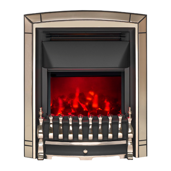
INSTALLER GUIDE 1. IMAGE © Baxi Heating U.K. Limited 2010. Page 5... -
Page 6: Handling And Unpacking
* An optional spacer frame kit is obtainable either from your firefront supplier or direct from Valor Fires Sales. The kit is a 50mm spacer kit (Kit number 5135632). One person should be sufficient to lift the firefront. If for any reason this weight is considered too heavy then obtain assistance. -
Page 7: Safety
Always use a fireguard when young children, infirm persons and pet animals can come into contact with the firefront. Always use genuine Valor Fires spare parts. Never Never leave children unsupervised in a room where the firefront is ON and unguarded. -
Page 8: Optional Spacer Frame Kit
Valor Fires Sales - spacer kit number 5135632. The spacer kit is an addition to the spacer supplied with the firefront. If you want the firefront to be fitted against a flat wall it will be necessary to purchase the kit, they are designed to be secured together. -
Page 9: Pack Contents
INSTALLER GUIDE 5. PACK CONTENTS Contents Quantity (Illustrations are not to scale) Firefront (Design may differ from that shown) Spacer frame 1 Only No. 8 x 3/8 pan head screw Tension wire Diffuser Boiler Control and connector lead. Control Knob Top coal Figure 2. -
Page 10: Fitting The Firefront
At least 25mm (At least 3 inches) * An optional spacer frame kit is obtainable either from your firefront supplier or direct from Valor Fires Sales. The kit is a 50mm spacer kit (Kit number 5135632). Moving the cable guide. -
Page 11: Removing The Cable Guide
INSTALLER GUIDE Removing the cable guide. 1. Before removing the cable guide please note that the wider part of the cable guide is on the outer edge of the base (See figure 3 - Item 1). 2. To remove the cable guide push and lift the tab on the bottom. -
Page 12: Fitting The Control Knob
INSTALLER GUIDE Fitting the Control Knob. The control knob is supplied separately with the accessory pack. Fit the control knob before continuing with the firefront installation. To assemble the control knob to the control spindle, firstly line up the ‘D’ profile on the underside of the control knob to the ‘D’... -
Page 13: Securing The Firefront
INSTALLER GUIDE Securing the Firefront. All fixings supplied with the firefront have been identified in figure 2. The firefront must be secured into position to prevent it from being tipped over. The following securing options are available: Method A - Securing with wire. Method B - Securing with wire using an Optional Spacer Frame kit (See section 4). - Page 14 INSTALLER GUIDE 5. At the top of the firefront there are four small holes, two each side of the firefront. From the front of the firefront, thread about 50mm of the wire into the outside small hole on the right side of the firefront (See point 1 - figure 8).
- Page 15 50mm deep spacer frame kit is obtainable either from your firefront supplier or direct from Valor Fires Sales. The spacer kit is an addition to the spacer supplied with the firefront. If you want the firefront...
-
Page 16: Fitting The Light Diffuser
INSTALLER GUIDE Fitting the light diffuser. 1. There is a light diffuser supplied with the firefront (See figure 10). Place this on to the metal flange below the plastic screen. Fitting the Fascia. 1. The magnets may have moved in transit. Locate the magnets as in figure 11. -
Page 17: Removing The Fascia And Firefront
INSTALLER GUIDE 7. REMOVING THE FASCIA AND FIREFRONT To gain access to the boiler for servicing and maintenance it will be necessary to remove the firefront. Do this as below: 1. Unscrew the ash pan knob and remove the Hearth casting from beneath the fascia. 2. -
Page 18: Owner Guide
OWNER GUIDE OWNER GUIDE FOR WARRANTY AND SERVICE INFORMATION SEE PAGES 27 TO 31 © Baxi Heating U.K. Limited 2010. Page 18... - Page 19 If you require further assistance, the Valor Fires Technical Helpline will be pleased to help. Please telephone 0844 8711 565 (local rates apply in the United Kingdom). In the Republic of Ireland please telephone 0044 844 8711 565.
-
Page 20: Image
OWNER GUIDE 1. IMAGE 2. SAFETY Warning! If you smell gas. Do not operate light switches. Do not operate any electrical equipment. Do not use a telephone in the hazardous area. Extinguish any naked flame and do not smoke. Open windows and doors in the hazardous area. Turn off the gas supply at the meter. - Page 21 Always use a fireguard when young children, infirm persons and pet animals can come into contact with the firefront. Always use genuine Valor Fires spare parts. Never Never leave children unsupervised in a room where the firefront is ON and unguarded.
-
Page 22: Operating The Firefront
OWNER GUIDE 3. OPERATING THE FIREFRONT Important Safety. Never cover the firefront or obstruct the openings at the base of the firefront, this could cause overheating and consequent risk of fire. Figure 1. Variable energy control. What are the Fireslide control positions for? The firefront is operated by the Fireslide control located on the upper right hand side of the firefront. -
Page 23: Operating The Boiler
OWNER GUIDE 4. OPERATING THE BOILER The Boiler Control is located on the upper right hand side of the firefront (See figure Figure 3. Boiler Control (Shown with door open) Note: To operate the Boiler Control the On / Off button needs to be pressed for a minimum of half a second. -
Page 24: How Do You Know When The System External Controls Are Requesting Heating Or Hot Water
OWNER GUIDE How do you know when the system external controls are requesting heating or hot water ? (When switched ON the boiler will be operated by a separate control. This may be a timer or room thermostat control). 1. When the boiler is ON and heat is required a vertical bar will appear in the top left of the display. -
Page 25: Lockout / Error Codes
OWNER GUIDE Lockout / Error codes. The following codes are user resettable. E110 – High limit thermostat or safety float switch operation. E125 – Boiler maximum water temperature exceeded twice in 2 hour period. E131 – Burner lockout after power OFF/ON during the fault E125. E133 –... -
Page 26: Cleaning And Maintaining The Firefront
OWNER GUIDE 5. CLEANING AND MAINTAINING THE FIREFRONT How do I clean my firefront? The firefront fascia and plastic parts need only to be wiped clean with a dry soft cloth, do not use polishes or abrasive materials. I have a problem with my firefront! Important Safety Before undertaking maintenance always disconnect the firefront from the electricity supply by removing the 3 pin plug and allowing the firefront to cool... -
Page 27: Environment
OWNER GUIDE 6. ENVIRONMENT Environmental Protection. Waste electrical products should not be disposed of with household waste. Please recycle where facilities exist. Check with your local authority or retailer for recycling advice. What should I do when I’m ready to dispose of my firefront? The plug should be removed from the mains cable and the mains cable cut from the firefront. - Page 28 OWNER GUIDE When calling heateam, it would be helpful if you could have the following information to hand:- Firefront serial number.* Firefront brand and model number.* Date of installation.* Proof of purchase (If you do not have the firefront serial number) *Note: Details 1 –...
- Page 29 OWNER GUIDE © Baxi Heating U.K. Limited 2010. Page 29...
-
Page 30: Installer Details
OWNER GUIDE All areas to be completed by the installer: INSTALLER DETAILS Installer Name Gas Safe Register or Corgi Registration Number. Company Name. Company Address Company Telephone number Company Fax number BOILER DETAILS Boiler Model Boiler Serial number (Can be found on the information label - See figure 4) A LABEL CONTAINING THE BOILER SERIAL... -
Page 31: Owner Guide
OWNER GUIDE FIREFRONT DETAILS Model Serial number (Can be found on the information label - See figure 5) A LABEL CONTAINING THE FIREFRONT SERIAL NUMBER LABEL SERIAL NUMBER MAY HAVE TO BE AFFIXED HERE BEEN PLACED INSIDE THIS BOX. Fascia name (Block Capitals) Fascia code - Can be found close to the information label (Block Capitals) A LABEL CONTAINING THE FASCIA CODE... - Page 32 © Baxi Heating U.K. Limited 2010.
Need help?
Do you have a question about the 824 Blenheim Longlite and is the answer not in the manual?
Questions and answers