Table of Contents
Advertisement
Quick Links
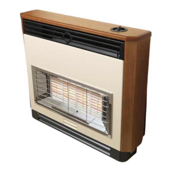
INSTALLATION AND OWNER GUIDE
Model 348
Brava
RADIANT / CONVECTOR GAS FIRE
Incorporating the VALOR FIRES
(G.C. No. 32-032-90)
We trust that this guide gives
sufficient details to enable this
appliance to be installed and
maintained satisfactorily. However, if
further information is required, our
Valor Fires Technical Helpline will
be pleased to help.
Telephone 0844 8711 565 (National
call rates apply in the United
Kingdom).
In the Republic of Ireland
Telephone 0044 844 8711 565.
INSTALLER: Please leave this guide with the owner
©
Baxi Heating U.K. Limited 2009.
5134763/01
CONTROL
Advertisement
Table of Contents

Related Manuals for Valor Fires 348 Brava


Summary of Contents for Valor Fires 348 Brava
- Page 1 However, if further information is required, our Valor Fires Technical Helpline will be pleased to help. Telephone 0844 8711 565 (National call rates apply in the United Kingdom).
- Page 2 Warning: Any person who does any unauthorised act in relation to a copyright work may be liable to criminal prosecution and civil claims for damages. Valor Fires, Erdington, Birmingham B24 9QP www.firesandstoves.co.uk Because our policy is one of constant development and improvement, details may vary slightly from those given in this publication ©...
- Page 3 BS EN ISO 9001 quality system accepted by the British Standards Institute. The Highest Standards Valor Fires is a member of SBGI and HHIC (Heating and Hot water Industry Council) that work to ensure high standards of safety, quality and performance. Careful Installation...
- Page 4 INSTALLER GUIDE INSTALLER GUIDE FOR OWNER GUIDE SEE PAGES 34 TO 47 © Baxi Heating U.K. Limited 2009. Page 4...
-
Page 5: Table Of Contents
INSTALLER GUIDE CONTENTS Section Heading Page INSTALLER GUIDE 4 - 33 OWNER GUIDE 34 - 47 1. SAFETY 2. LIST OF ACCESSORIES 3. APPLIANCE DATA, EFFICIENCY AND NOx 3.1 Appliance data. 3.2 Efficiency. 3.3 NOx 4. GENERAL INSTALLATION REQUIREMENTS 4.1 Regulations, Standards and Law. 4.2 Ventilation. -
Page 6: Installer Guide
INSTALLER GUIDE CONTENTS (Continued) Section Heading Page 7. CONTROL & PRESSURE CHECKS 7.1 Check control settings. 7.2 Flame supervision and spillage monitoring system. 7.3 Check reference pressure. 8. FASCIA FITTING 8.1 To fit the fascia. 8.2 To fit the closure plate baffle. 9. -
Page 7: Safety
INSTALLER GUIDE 1. SAFETY Installer Before continuing any further with the installation of this appliance please read the following guide to manual handling: The approximate lifting weight of this appliance is 20.6kg (including ceramic plaques) . One person should be sufficient to lift the fire. If for any reason this weight is considered too heavy then obtain assistance. -
Page 8: Appliance Data, Efficiency And Nox
Model Efficiency % (Gross) 348 Brava Fireslide 74.0 The gross calorific value of the fuel has been used for this efficiency calculation. The test data from which it has been calculated has been certified by GL Industrial services (0087). -
Page 9: Nox
INSTALLER GUIDE 3.3 NO x The natural gas 'weighted' NO x result is 295.4 mg/kWh which equates to a NO x class 2 when tested in accordance with clause 6.5.5. of BS 7977-1. 4. GENERAL INSTALLATION REQUIREMENTS 4.1 Regulations, Standards and Law. The installation must be in accordance with these instructions. -
Page 10: Ventilation
INSTALLER GUIDE Ireland) issued by the Department of the Environment for Northern Ireland. In the Republic of Ireland the installation must be carried out by a competent person and installed in accordance with: a) The current edition of IS 813 “Domestic gas installations”. b) All relevant national and local rules in force. -
Page 11: Fireplace Preparation
INSTALLER GUIDE 4.6 Fireplace preparation. 4.6.1 The appliance can be fitted to a purpose made proprietary class “O” 150°C surround. 4.6.2 If the fireplace opening is an underfloor draught type, it must be sealed to stop any draughts. 4.6.3 The front of the fireplace should be flat over an area sufficient to ensure a good seal with the closure plate. -
Page 12: Fireplace Clearances
INSTALLER GUIDE 4.7 Fireplace clearances. 4.7.1 The minimum allowable distance from the outside of the appliance fascia to a corner wall having combustible material or any other combustible surface which projects beyond the front of the appliance is 100mm at either side (See figure 2). Although no side clearance is necessary to non-combustible surfaces we recommend a 100mm clearance for service access to the fascia side fixings and for operating the slider control. -
Page 13: The Flue Spigot
250mm downwards measured from the bottom of the flue spigot (See figure 4). 4.8.2 A spigot extension is available (Valor Fires part number 0595191). When fitted this shall extend through the closure plate for at least 38mm and have a minimum clearance of 50mm from the end to any surface. -
Page 14: The Hearth
INSTALLER GUIDE 4.9. The hearth. The appliance must be mounted on a non-combustible hearth except when the conditions in section 4.10.3 are met (N.B. conglomerate marble hearths are considered as non-combustible). The hearth must be at least 680mm wide x 300mm deep. - Page 15 INSTALLER GUIDE The fireplace opening must be within the following dimensions: Precast flue Width Height Max. 440mm Max. 610mm Min. 305mm Min. 544mm The total height of the closure plate is 660mm and will accommodate a maximum opening height of 650mm (This allows a 10mm overhang). Heights above 580mm (Inclusive of sealing tape) will leave the sealing tape and closure plate visible above the appliance.
-
Page 16: Flues
INSTALLER GUIDE Wall mounting to a pre cast flue. Important: If the base of the opening is above the finished floor level it must be a maximum 350mm from the finished floor level. This will ensure that the air relief hole in the closure plate is not covered or reduced. -
Page 17: Pre-Installation Preparation
INSTALLER GUIDE terminal, shall be not less than 3m in actual vertical height. When calculated in accordance with BS 5440: Part 1 Annex B, the minimum equivalent height of the flue shall be 2.0m of 125mm dia. flue pipe. The flue must be clear of any obstruction and its base must be clear of debris. The flue must be completely sealed so that combustion products do not come into contact with combustible materials outside the chimney. -
Page 18: Appliance Preparation
INSTALLER GUIDE 5.2 Appliance preparation. 1. Stand the fire upright. 2. Remove the two transit screws from near the top of the back panel wings (See figure 5). 3. Remove the two knurled fascia retaining screws located at the rear of the fascia near the bottom. -
Page 19: Ignition
INSTALLER GUIDE 5.4 Ignition. Before attempting to install, it is worth checking that the electronic spark ignition system operates satisfactorily. To initiate the spark, slide the control knob down as far as it will go and retain in this position. Sparks should be generated between the electrode and thermocouple tip on the pilot unit. - Page 20 INSTALLER GUIDE 5.6.1Fitting the closure plate when hearth mounting. (See figure 9). The closure plate must be fitted and sealed to the hearth and fireplace opening using a suitable heat resistant material. If necessary cut the closure plate but make sure that it overlaps the fireplace opening sufficiently to allow satisfactory sealing.
-
Page 21: Appliance Installation
INSTALLER GUIDE spigot opening must be at least the minimum dimension shown in figure 10. 5.6.3 Check the flue pull with closure plate fitted by applying a lighted match or smoke match to the flue spigot opening in the closure plate and observe the smoke. If there is a definite flow continue with the installation. -
Page 22: Gas Supply Connection
INSTALLER GUIDE Figure 12. 6.3 Gas supply connection. 8mm rigid tubing must be used to connect the gas supply to the appliance. An olive and nut are provided for connection to the “T” connector on the appliance. The connector can be rotated to allow connection from either side or the rear. The connector includes a valve for isolating the gas supply. -
Page 23: Flue Restrictor Adjustment
INSTALLER GUIDE 6.5 Flue restrictor adjustment. (See figure 13). The appliance has an integral adjustable flue draught restrictor. This is supplied set in the fully open (unrestricted) position and in most cases no adjustment should be necessary. It can be reset to a fully restricted position if the flue draught is excessive. -
Page 24: Control & Pressure Checks
INSTALLER GUIDE 7. CONTROL & PRESSURE CHECKS Please note: When operating the fire for the first time, some vapours may be given off which could set off smoke alarms in the vicinity. These vapours are quite normal with new appliances. They are totally harmless and will disappear after a few hours use. 7.1 Check control settings. -
Page 25: Flame Supervision And Spillage Monitoring System
INSTALLER GUIDE 7.2 Flame supervision and spillage monitoring system. This pilot unit includes a system that will automatically shut off the gas supply if the pilot flame goes out or if there is insufficient oxygen due to spillage or poor ventilation. Check that the system operates properly as follows: 1. -
Page 26: Fascia Fitting
INSTALLER GUIDE 8. FASCIA FITTING Before continuing with the installation of this appliance it is important that the information contained on the back pages of the Owner guide is completed. 8.1 To fit the closure plate baffle. The closure plate baffle is supplied with the fire and is intended for use where the height of the closure plate and sealing tape is greater than 580mm. -
Page 27: Spillage Check
INSTALLER GUIDE 9. SPILLAGE CHECK A spillage check must be made before leaving the installed appliance with the customer. Make this with all radiants and complete fascia in position. 1. Close all doors and windows in the room containing the fire. 2. -
Page 28: Final Review
INSTALLER GUIDE 10. FINAL REVIEW COMPLETE THE INFORMATION IN THE WARRANTY AND SERVICE SECTION OF THE OWNER GUIDE (See last pages of the OWNER guide). Make sure that the dress guard is securely in position. Recheck the operation of the fire at all control positions. Visually inspect the appliance. -
Page 29: Servicing & Parts Replacement
INSTALLER GUIDE 11. SERVICING & PARTS REPLACEMENT Always turn off the gas supply and allow the appliance to cool completely before commencing any servicing (The appliance inlet “T” connector incorporates an isolating valve). It is recommended that, at least once a year, the appliance is disconnected and the catchment space behind the closure plate checked and cleared of any debris. -
Page 30: To Remove The Electronic Igniter Unit
INSTALLER GUIDE 11.3 To remove the electronic igniter unit. 1. Remove the fascia as in section 11.2. 2. Remove the battery from the igniter unit. 3. Note the location of the leads to the igniter unit then disconnect them ensuring that it is the tags that are held and not the leads. -
Page 31: To Remove The Complete Burner Module, Pipes And Pilot
INSTALLER GUIDE 7. Carefully slide the burner module to the right to free it from the right side of the radiant box (See figure 18). 11.7 To remove the complete burner module, pipes and pilot. 1. Remove the fascia as in section 11.2. 2. -
Page 32: To Remove The 'T' Piece
INSTALLER GUIDE prevent possible damage to the microswitch. 4. Remove the hexagonal bolt securing the control pivot bracket to the controller at the rear. 5. Remove the control pivot bracket. 6. Detach the lower injector pipe at the top of the gas flow rate controller. Support the controller while detaching to prevent excessive strain. -
Page 33: To Grease The Gas Flow Rate Controller
INSTALLER GUIDE 11.11 To grease the gas flow rate controller. 1. Remove the fascia as in section 11.2. 2. Disconnect the slider control by removing the knurled screw from the connector arm. 3. Remove the nut and washer securing the control pivot bracket to the controller at the front. -
Page 34: Owner Guide
OWNER GUIDE OWNER GUIDE FOR WARRANTY AND SERVICE INFORMATION SEE PAGES 43 TO 47 © Baxi Heating U.K. Limited 2009. Page 34... - Page 35 OWNER GUIDE LIST OF CONTENTS Section Page SAFETY APPLIANCE DIMENSIONS OPERATING YOUR FIRE GAS CONSUMPTION The Oxysafe flame sensing and flue blockage safety system. Settings. To turn the fire off. Lighting with a match or taper. CLEANING YOUR FIRE REPLACING THE RADIANTS MAINTENANCE Battery replacement Regular maintenance.
- Page 36 OWNER GUIDE SAFETY IF YOU SMELL GAS DON’T SMOKE. EXTINGUISH ALL NAKED FLAMES. DON’T TURN ELECTRICAL SWITCHES ON OR OFF. TURN OFF THE GAS SUPPLY AT THE METER OR TANK AS APPROPRIATE. OPEN DOORS AND WINDOWS TO GET RID OF THE GAS. IMMEDIATELY CALL THE GAS EMERGENCY SERVICE FROM A NEIGHBOURS PHONE - SEE YOUR LOCAL TELEPHONE DIRECTORY.
- Page 37 OWNER GUIDE Do get advice about the suitability of any wall covering near your fire. Soft wall coverings (e.g. embossed vinyl, etc.) which have a raised pattern are easily affected by heat. They may, therefore, scorch or become discoloured when close to a heating appliance.
- Page 38 OWNER GUIDE APPLIANCE DIMENSIONS Model Dimension ‘A’ (mm) Dimension ‘B’ (mm) Dimension ‘C’ (mm) Brava Figure 2. Dimensions and clearances OPERATING YOUR FIRE PLEASE NOTE When operating your fire for the first time, some vapours may be given off which may cause a slight odour and could possibly set off any smoke alarms in the immediate vicinity.
- Page 39 OWNER GUIDE 1. Slide the control button to the ignition / low ( L) position. In this position, the electronic ignition system should cause a series of sparks that should light the pilot. The pilot flame can be seen through a hole immediately in front of the centre radiants (See the upper section of figure 3).
- Page 40 OWNER GUIDE Lighting with a match or taper. (See figure 3). In the unlikely event of failure of the ignition spark, the pilot can be lit by a taper or long spill. Slide the control knob to the ignition / low position ( L).
- Page 41 OWNER GUIDE REPLACING THE RADIANTS Always use the correct type of replacement radiant. Ask for Valor Fires part number 5132071 (Single Radiant). Turn the fire off and allow it to cool before attempting to remove the radiants. (See figure 4).
- Page 42 OWNER GUIDE MAINTENANCE Battery replacement. 1. The electronic ignition unit is located at the base of the fire on the right hand side (See figure 5). 2. To access the electronic ignition unit battery the fascia will have to be removed. The fascia securing screws are located at the bottom rear of the fascia.
- Page 43 OWNER GUIDE WARRANTY AND SERVICE Standard Warranty Terms & Conditions The warranty is for 12 months subject to contract. In the United Kingdom servicing can be carried out either by a heateam service engineer or a GAS SAFE REGISTER engineer. Outside of the United Kingdom servicing can be carried out either by a CORGI or GAS SAFE REGISTER engineer.
- Page 44 OWNER GUIDE When calling heateam, it would be helpful if you could have the following information to hand:- Fire serial number and fascia code (The serial number can be found on the serial number label - See figure 7 on page 47).* Date of installation.* Your installer name and address details.* Fire make and model number.*...
- Page 45 OWNER GUIDE © Baxi Heating U.K. Limited 2009. Page 45...
- Page 46 OWNER GUIDE To be completed by installer: Installer Details (Block Capitals) Installer Name Gas Safe Register or Corgi Registration Number. Company Name. Company Address Company Telephone number Company Fax number © Baxi Heating U.K. Limited 2009. Page 46...
-
Page 47: Owner Guide
OWNER GUIDE Model Serial number (Can be found on the serial number label - See figure 7) A LABEL CONTAINING THE SERIAL NUMBER MAY HAVE BEEN PLACED INSIDE THE BOX. Fascia name (Block Capitals) Fascia code - Can be found close to the information label (Block Capitals) A LABEL CONTAINING THE FASCIA CODE MAY HAVE BEEN PLACED... - Page 48 © Baxi Heating U.K. Limited 2009.
Need help?
Do you have a question about the 348 Brava and is the answer not in the manual?
Questions and answers