Table of Contents
Advertisement
Quick Links
Contents
Motherboard 4845PE
1. 4845PE Specifications .......................4
1.1 Introduction ............................................................ 4
1.2 Package Contents .................................................. 5
1.3 Specifications and Features .................................. 6
CPU Processor ........................................................................... 6
Chipset ........................................................................................ 6
PCI .............................................................................................. 6
DDR SDRAM Memory ............................................................... 6
Bus Slots ..................................................................................... 6
Universal Serial Bus .................................................................. 6
WOL (Wake On LAN) ................................................................ 6
Award BIOS ................................................................................ 7
ATA 100 On Board ..................................................................... 7
PCI-Based AC 97 Digital Audio Processor ............................... 7
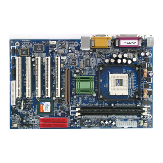
1.4 4845PE Layout Diagram ...................................... 8
1.5 CPU and CPU Fan Installation ............................ 10
1.5.1 CPU Installation with Socket 478 ................................... 10
1.5.2 CPU Fan Installation with P4 Fan Base ........................... 11
1.6 DDR SDRAM Installation ................................. 12
1.7 Connectors & Jumpers Setting ........................... 13
1.7.1 Back Panel I/O Connectors ............................................. 13
1.7.1.1 PS/2 Mouse / Keyboard CONN. .............................................. 1 3
1.7.1.2 USB Ports: USB0/1 ..................................................................... 1 3
1.7.1.3 Serial Interface Port: COM1/COM2A ................................. 1 4
Motherboard 4845PE
0-1
Advertisement
Table of Contents

Related Manuals for Acorp 4845PE


Summary of Contents for Acorp 4845PE
-
Page 1: Table Of Contents
Award BIOS ................7 ATA 100 On Board ..............7 PCI-Based AC 97 Digital Audio Processor ....... 7 1.4 4845PE Layout Diagram ........8 1.5 CPU and CPU Fan Installation ......10 1.5.1 CPU Installation with Socket 478 ........10 1.5.2 CPU Fan Installation with P4 Fan Base ...... - Page 2 Contents Motherboard 4845PE 1.7.1.4 Parallel Interface Port .............. 1 4 1.7.1.5 Joystick / Midi Connector ............1 4 1.7.1.6 Audio Port Connectors ............. 1 4 1.7.2 ATX Main Power Connectors: PW1/PW2 ...... 15 1.7.3 Floppy Disk Connector: FDD .......... 16 1.7.4 Hard Disk Connectors: IDE1/IDE2 ........
- Page 3 Contents Motherboard 4845PE 2.1 BIOS Support ............28 2.2 Main Menu ............31 2.3 Standard CMOS Features ........34 2.4 Advanced BIOS Features ........38 2.5 Advanced Chipset Features ........ 42 2.6 Integrated Peripherals ......... 45 2.7 Power Management Setup ........49 2.8 PnP/PCI Configurations ........
-
Page 4: 45Pe Specifications
Motherboard 4845PE 1. 4845PE Specifications 1.1 Introduction The 4845PE motherboard is an integration of Intel P4 CPUs in Socket-478 packaging and the North Bridge i845PE supporting 533/400 MHz Front Side Bus. North Bridge i845PE on board also supports DDR 333/... -
Page 5: Package Contents
Chapter 1 Motherboard 4845PE 1.2 Package Contents HDD UDMA66/100 Cable. FDD Cable. Flash Memory with BIOS. USB2/3 Cable (Optional). Fully Setup Driver CD with built in utilities. User Manual. -
Page 6: Specifications And Features
| Support Intel Netburst Micro-architecture. * The higher frequency CPU should be compatible with Intel CPU specificiation and the motherboard latest BIOS version which will be released in Acorp Web Site: www.acorp.com.tw Chipset | Intel 845PE North Bridge. | Intel ICH4 South Bridge. -
Page 7: Award Bios
Chapter 1 Motherboard 4845PE Award BIOS | Supporting Plug & Play specification which detects the peripheral devices and expansion cards automatically | Supporting CD-ROM, SCSI, LAN BOOT, Temperature sen- sor, LAN, Alarm Bus CLK setup | Supporting Desktop Management Interface (DMI) func-... -
Page 8: 4845Pe Layout Diagram
Chapter 1 Motherboard 4845PE 1.4 4845PE Layout Diagram Socket 478 Intel 845PE AGP4X PCI 1 PCI 2 Intel ICH4 PCI 3 PCI 4 PCI 5 Battery 26 27 28... - Page 9 Chapter 1 Motherboard 4845PE 4845PE Component Layout Description: 1. Jp11: USB2 5V or +5Vsb Selector 2. IDE 1: Primary IDE Connector 3. IDE 2: Secondary IDE Connector 4. PW 2: ATX Main Power Connector 5. Fan 2: Cooling Fan Connector 6.
-
Page 10: Cpu And Cpu Fan Installation
Chapter 1 Motherboard 4845PE 1.5 CPU and CPU Fan Installation This motherboard is designed with Socket 478 for Intel P4 processor. 1.5.1 CPU Installation with Socket 478 1. Pull the lever sideways away from the socket then raise the lever to a 90-degree angle. -
Page 11: Cpu Fan Installation With P4 Fan Base
Chapter 1 Motherboard 4845PE 1.5.2 CPU Fan Installation with P4 Fan Base 1. P4 CPU Fan is typically designed with 4 latches and mounted with a thick heatsink. Please do not use other type of CPU fan which cannot match the P4 Fan base on board. -
Page 12: Ddr Sdram Installation
Chapter 1 Motherboard 4845PE 1.6 DDR SDRAM Installation This motherboard supports a maximized 2GB DDR SDRAM. It provides two184-pin unbuffered DDR sockets. It supports 64MB to 1GB DDR memory module. DDR SDRAM Installation Procedures: 1. The DDR socket has a “Plastic Safety Tab” and the DDR memory module has an asymmetrical notch”, so the DDR... -
Page 13: Connectors & Jumpers Setting
Chapter 1 Motherboard 4845PE 1.7 Connectors & Jumpers Setting 1.7.1 Back Panel I/O Connectors This motherboard provides the following back panel connectors: (Optional) MIDI/Game Parallel(Printer) Port RJ45 (15-pin female) 25-pin female PS/2 Mouse USB0 PS/2 Keyboard COM1 Speaker COM2A USB1... -
Page 14: Serial Interface Port: Com1/Com2A
Chapter 1 Motherboard 4845PE 1.7.1.3 Serial Interface Port: COM1/COM2A The serial interface port is sometimes referred to as an RS- 232 port or an asynchronous communication port. Mice, printers, modems and other peripheral devices can be connected to a serial port. The serial port can also be used to connect computer systems together . -
Page 15: Atx Main Power Connectors: Pw1/Pw2
Chapter 1 Motherboard 4845PE 1.7.2 ATX Main Power Connectors: PW1/PW2 This connector supports the power button on-board. Using the ATX power supply, functions such as Modem Ring Wake- Up and Soft Power Off are supported on this motherboard . T h i s p o w e r c o n n e c t o r s u p p o r t s i n s t a n t p o w e r - o n functionality, which means that the system will boot up instantly when the power connector is inserted on the board. -
Page 16: Floppy Disk Connector: Fdd
Chapter 1 Motherboard 4845PE 1.7.3 Floppy Disk Connector: FDD This connector supports the provided floppy drive ribbon cable. After connecting the single end to the board, connect the two plugs on the other end to the floppy drives. 1.7.4 Hard Disk Connectors: IDE1/IDE2 These connectors are provided with IDE hard disk ribbon cable into the package . -
Page 17: Cd Audio-In Connectors: Cdin1/Cdin2
Chapter 1 Motherboard 4845PE 1.7.6 CD Audio-In Connectors: CDIN1/CDIN2 CDIN1 and CDIN2 are the connectors for CD-Audio Input signal. Please connect them to CD-ROM CD-Audio output connector. CDIN1 and CDIN2 have the same pin assignment but different pin pitch. Definition... -
Page 18: Usb Pin Headers: Usb1 & Usb2
Chapter 1 Motherboard 4845PE 1.7.8 USB Pin Headers: USB1 & USB2 USB1 and USB2 are 2x5 Pin Headers for support of external USB ports. Each USB pin header requires a USB cable for expansion of two USB ports. This optional USB cable is available from your motherboard dealer or vendor. -
Page 19: Front Panel Connectors: Panel1
Chapter 1 Motherboard 4845PE 1.7.9 Front Panel Connectors: PANEL1 Front Panel Connectors Socket 478 G LED G-BUN HD LED Intel 845PE (Void) (Void) Intel ICH4 PS SW PSSW The system power is controlled by a momentary switch connected to this lead. Pushing the button once will switch the system ON. -
Page 20: Ir Infrared Module: Ir1 Connector
Chapter 1 Motherboard 4845PE SMI Suspend Switch Lead (G-BUN) (Disabled) This allows the user to manually place the system into a suspend mode of Green mode. System activity will be instantly decreased to save electricity and expand the life of certain components when the system is not in use. -
Page 21: Smart Card Connector: Sc1 (Optional)
Chapter 1 Motherboard 4845PE 1.7.11 Smart Card Connector: SC1 (optional) This optional connector supports the Smart Card function providing the connection with aan external Smart card. 1.7.12 Audio-in Connectors: AUXIN1 & VOIN1 No.17 AUXIN1 and No.18 VOIN1 are connectors supporting supporting the external audio-out devices. -
Page 22: Smart Panel Connectors (Optional)
Chapter 1 Motherboard 4845PE 1.7.13 Smart Panel Connectors (optional): ERR1 Socket 478 Intel 845PE Intel ICH4 COM2 (No. 21 COM2,No.23 Jp5, No.33 Jp2, No. 35 ERR1) The motherboard provides the pin leads COM2, Jp2, Jp5 and ERR1 for Smart Panel connection. If you want POST Error Code or Smart Panel function, please refer to Smart Panel manual (version 2.0 ). -
Page 23: Spii Printer Error Led Port: Err1
Chapter 1 Motherboard 4845PE 1.7.13.2 SPII Printer Error LED Port: ERR1 For Smart Panel connector ERR1 to M/B ERR1. Assignment Assignment ERD4 ERD0 ERD5 ERD1 ERD6 ERD2 ERD7 ERD3 1.7.13.3 Second BIOS Connector: Jp5 For Smart Panel connector Jp5 to M/B Jp5. -
Page 24: Cmos Function Selector: Jp10
Chapter 1 Motherboard 4845PE 1.7.14 CMOS Function Selector: Jp10 When you have problem with booting system, you may clear CMOS to restore the optimum default BIOS data. Pin Jp10 Function Normal Socket 478 closed (Default) Clear CMOS Intel 845PE closed... -
Page 25: Cpu Clock Frequency Selector: Jp7
Chapter 1 Motherboard 4845PE 1.7.16 CPU Clock Frequency Selector: Jp7 Overclocking is to operate a CPU with a frequency which surpass the default CPU clock. Jp7 jumper is designed to offer a chance for CPU overclocking.when starting system. If a 100MHz CPU is used on board, setting Jp7 to 1-2 closed or 2-3 closed will not offer a chance of overclocking from 100MHz to 133MHz. -
Page 26: Usb2 Wake-Up Selector: Jp1
Chapter 1 Motherboard 4845PE 1.7.17 USB2 Wake-up Selector: Jp11 Jp11 is designed to select the USB2 wake up function: Socket 478 Pin Jp11 Function Disabled closed (Default) Intel 845PE Enabled closed Intel ICH4 1.7.18 USB1 Wake-up Selector : Jp8 Jp8 is designed to select the USB1 wake up function:... -
Page 27: Ports Usb0/1 Wake-Up Selector: Jp4
Chapter 1 Motherboard 4845PE 1.7.19 Ports USB0/1 Wake-up Selector: Jp4 Jp4 is designed to select the USB2 connector voltage: Pin Jp4 Function Socket 478 Disabled closed (Default) Intel 845PE Enabled closed Intel ICH4 1-27... -
Page 28: Bios Setup
Chapter 2 4845PE BIOS Setup Chapter 2 BIOS Setup 2. BIOS Setup 2.1 BIOS Support This chapter discusses the Award BIOS Setup program built in the ROM BIOS. The Setup program allows the user to modify the basic system configuration. The modification is then stored in battery-backed RAM so that it can retain the setup information after the power is turned off. -
Page 29: Cpu Support
Chapter 2 4845PE BIOS Setup APM Support This AWARD BIOS supports Version 1.1&1.2 of the Advanced Power Management(APM) specification.Power management features are implemented via the System Management Interrupt(SMI). Sleep and Suspend power management modes are supported. Power to the hard disk drives and video monitors can be managed by this AWARD BIOS. - Page 30 Chapter 2 4845PE BIOS Setup Keystroke Function Up arrow Move to previous item Down arrow Move to next item Left arrow Move to the item on the left(menu bar) Right arrow Move to the item on the right(menu bar) Main Menu: Quit without saving changes...
-
Page 31: Main Menu
Chapter 2 4845PE BIOS Setup 2.2 Main Menu Once you enter AWARD BIOS CMOS Set up Utility, the Main Menu will appear on the screen and allows you to se- lect from several setup function. Use the arrow keys to se- lect the items and press<Enter>... - Page 32 Chapter 2 4845PE BIOS Setup Standard CMOS Features This setup page includes all the items in standard compatible BIOS. Advanced BIOS Features This setup page includes all the items of the BIOS special enchanced features. Advanced Chipset Features This setup page includes all the items of the Chipset special enchanced features.
- Page 33 Chapter 2 4845PE BIOS Setup Load Optimized Defaults These settings are for configuring a workable computer when something is wrong. If you cannot boot the computer successfully, select the BIOS Setup options and try to diagnose the problem after the computer boots. These settings do not provide optional performance.
-
Page 34: Standard Cmos Features
Chapter 2 4845PE BIOS Setup 2.3 Standard CMOS Features This main option in the Standard CMOS Setup Menu is divided into 10 fields or items. Each field provides one or more setup choices. Use the arrow keys to highlight the field and then use the <PgUp>... - Page 35 Chapter 2 4845PE BIOS Setup Main Menu Selections This table shows the selections that you can make on the Main Menu. Item Options Description Date Month Day Year Set the system,date. Note that the (mm : dd :yy) ‘Day’ automatically changes when you set the data.
- Page 36 Chapter 2 4845PE BIOS Setup Item Options Description Halt On All Errors Select the situation in which you No Errors want the BIOS to stop the POST All, but Keyboard process and notify. All, but Diskette All, but Disk/Key Base Memory (640K) The amount of conventional mem- ory detected during boot up.
- Page 37 Chapter 2 4845PE BIOS Setup IDE HDD Auto-Detection Press Enter on this item to let BIOS auto-detect your Hard Disk and show all the Primary Hard Disk Parameters ( Capacity, Cylinder, Head, Precomp, Landing Zone, Sector) on the menu. IDE Primary(Master/Slave) / Secondary(Master/Slave) This item allows you to detect the Hard Disk in 3 ways.
-
Page 38: Advanced Bios Features
Chapter 2 4845PE BIOS Setup 2.4 Advanced BIOS Features Phoenix - AwardBIOS CMOS Setup Utility Advanced BIOS Features Virus Warning Disabled Item Help CPU L1 & L2 Cache Enabled Quick Power On Self Test Enabled First Boot Device Floopy Second Boot Device... - Page 39 Chapter 2 4845PE BIOS Setup CPU L1 & L2 Cache These fields allow you to Enable or Disable the CPU’s L1(Internal) / L2(External) cache to provide better performance. The choices: Enabled(default); Disabled Quick Power On Self Test This category speeds up Power on self-Test(POST) after you power up the computer.
- Page 40 Chapter 2 4845PE BIOS Setup Boot Up NumLock Status Select power on state for Numlock.. The Choices On (default): Numpad is number keys; Off: Numpad is arrow keys; Gate A20 Option Select if chipset or keyboard controller should control Gate A20.
- Page 41 Chapter 2 4845PE BIOS Setup OS Select For DRAM >64MB Select the operating system that is running with greater than 64MB of RAM on the system. The Choices: Non-OS2(default), OS2. HDD S.M.A.R.T. Capability Allows user to choose the Self-monitoring Analysis and Reporting Technology for Hard Disk Drive.
-
Page 42: Advanced Chipset Features
Chapter 2 4845PE BIOS Setup 2.5 Advanced Chipset Features This section allows you to configure the system based features of the installed chipset. This chipset manages bus speeds and access to system memory resources, such as DRAM and external cache. It also coordinates communica- tions of the PCI bus. - Page 43 Chapter 2 4845PE BIOS Setup DRAM Timing Selectable Use this item to select the DRAM Timing mode. The Choices: By SPD: DRAM Timing is by Serial Presence Detect (SPD) which is located on the memory module itself. Manual: DRAM Timing is set manually with the options following this item below.
- Page 44 Chapter 2 4845PE BIOS Setup Video BIOS Cacheable Enabled: Enable Video BIOS Cacheable. Disabled (default):Disable Video BIOS Cacheable. Memory Hole At 15-16M In order to improve performace, certain space in memory can be reserved for ISA cards. This memory must be mapped into the memory's space below 16MB.
-
Page 45: Integrated Peripherals
Chapter 2 4845PE BIOS Setup 2.6 Integrated Peripherals Phoenix - AwardBIOS CMOS Setup Utility Integrated Peripherals Item Help Onchip Primary PCI IDE Enabled IDE Primary Master PIO Auto IDE Primary Slave PIO Auto IDE Primary Master UDMA Auto IDEPrimary Slave UDMA... - Page 46 Chapter 2 4845PE BIOS Setup On-Chip Primary PCI IDE Use this item to enable or disable the primary IDE channels that are integrated on the mainboard. The Choices: Enabled (default); Disabled IDE Primary Master/Slave PIO Auto (default):BIOS will automatically detect the IDE HDD Accessing mode.
- Page 47 Chapter 2 4845PE BIOS Setup USB 2.0 Controller If USB Controller is enabled, use this item to enable or disable USB 2.0 controller. The Choices: Enabled (default); Disabled USB Keyboard Support If USB Controller is enabled, use this item to enable or disable the USB Keyboard Support.
- Page 48 Chapter 2 4845PE BIOS Setup UART Mode Select This item allows you to select which Infra Red(IR) function of the onboard I/O chip you wish to use. The Choices: Normal(default), IrDA, SCR, ASKIR. UR2 Duplex Mode This item allows you to select which Infra Red(IR) function of the onboard I/O chip you wish to use.
-
Page 49: Power Management Setup
Chapter 2 4845PE BIOS Setup 2.7 Power Management Setup Phoenix - AwardBIOS CMOS Setup Utility Power Management Setup ACPI Function Enabled Item Help ACPI Suspend Type S1(POS) Power Management User Define Video Off Method V/H Sync+Blank Video Off In Suspend... - Page 50 Chapter 2 4845PE BIOS Setup ACPI Suspend Type The choices are for setting the ACPI Suspend Type. S1(Power On Suspend)(default); S3(Suspend To RAM); S1&S3 Power Management The choices are for setting the Power management mode: User Define (default); Min Saving; Max Saving.
- Page 51 Chapter 2 4845PE BIOS Setup Soft-off by PWR-BTTN Enables you to set the power button function in DOS. The Choices: Instant off(default); Delay 4 Sec. Power On By PME Use this item to enable/disable the Power On by PME function.
- Page 52 Chapter 2 4845PE BIOS Setup Reload Global Timer Events: When enabled, the following devices listed below will restart the global timer for Standby mode. Primary IDE 0/1 The choices:Disabled (default); Enabled Secondary IDE 0/1 The choices:Disabled (default); Enabled. FDD, COM, LPT Port The choices: Disabled (default);...
-
Page 53: Pnp/Pci Configurations
Chapter 2 4845PE BIOS Setup 2.8 PnP/PCI Configurations This section describes configuration of the PCI bus system. PCI or Personal Computer Interconnect, is a system which allows I/O devices to operate at speeds nearing the speed of the CPU itself when communicating with the com- ponents on board. - Page 54 Chapter 2 4845PE BIOS Setup Reset Configuration Data The system BIOS supports the PnP feature so the system needs to record which resource is assigned and proceeds to get rid of resource conflict. Every peripheral device has a node, which is called ESCD (Extended System Configuration Data.
- Page 55 Chapter 2 4845PE BIOS Setup IRQ Resources When resources are controlled manually, assign each system interrupt a type, depending on the type of device using the interrupt. PCI / VGA Palette Snoop Choose Disabled or Enabled. Some graphic controllers which...
-
Page 56: Pc Health Status
Chapter 2 4845PE BIOS Setup 2.9 PC Health Status Phoenix - AwardBIOS CMOS Setup Utility PC Health Status Item Help Vccp Vcc 1.5V Vcc 3.3V Vcc 5.0V Vcc 12.0V Vsb 5.0V Voltage Battery System Temperature CPU Temperature Fan 1 Speed... -
Page 57: Frequency/Voltage Control
Chapter 2 4845PE BIOS Setup 2.10 Frequency/Voltage Control Phoenix - AwardBIOS CMOS Setup Utility Frequency/Voltage Control Item Help CPU Clock Ratio Auto Detect PCI CLK Ensabled Spread Spectrum Disabled CPU Clock 100MHz ←→↑↓: Move Enter:Select +/-/PU/PD:Value F10:Save ESC:Exit F1:General Help... -
Page 58: Load Fail-Safe Defaults
Chapter 2 4845PE BIOS Setup 2.11 Load Fail-Safe Defaults When you press <Enter> on this item, you get a confirmation dialog box with a message similar to below: Phoenix - AwardBIOS CMOS Setup Utility Frequency/Voltage Control Standard CMOS Features Load Fail-safe Defaults... -
Page 59: Load Optimized Defaults
Chapter 2 4845PE BIOS Setup 2.12 Load Optimized Defaults When you press <Enter> on this item, you get a confirmation dialog box with a message similar to: Phoenix - AwardBIOS CMOS Setup Utility Frequency/Voltage Control Standard CMOS Features Load Fail-safe Defaults... -
Page 60: Set Supervisor / User Password
Chapter 2 4845PE BIOS Setup 2.13 Set Supervisor / User Password Phoenix - AwardBIOS CMOS Setup Utility Frequency/Voltage Control Standard CMOS Features Load Fail-safe Defaults Advanced BIOS Features Load Optimized Defaults Advanced Chipset Features Set Supervisor Password Integrated Peripherals Set User Password... -
Page 61: Save & Exit Setup
Chapter 2 4845PE BIOS Setup 2.14 Save & Exit Setup Phoenix - AwardBIOS CMOS Setup Utility Frequency/Voltage Control Standard CMOS Features Load Fail-safe Defaults Advanced BIOS Features Load Optimized Defaults Advanced Chipset Features Save to CMOS & Exit (Y/N)? Y... -
Page 62: Exit Without Saving
Chapter 2 4845PE BIOS Setup 2.15 Exit Without Saving Phoenix - AwardBIOS CMOS Setup Utility Frequency/Voltage Control Standard CMOS Features Load Fail-safe Defaults Advanced BIOS Features Load Optimized Defaults Advanced Chipset Features Set Supervisor Password Integrated Peripherals Quit Without Saving (Y/N)? N... -
Page 63: Drivers & Utilities
Chapter 3 4845PE Drivers & Utilities Chapter 3 Drivers & Utilities 3. Drivers & Utilities There are motherboard drivers and utilities included in the disc attached in this motherboard package. You don't have to install all of them for booting your system. But after... -
Page 64: Installing Intelinf
Chapter 3 4845PE Drivers & Utilities 3.2 Installing Intelinf Enter the item "INTEL CHIPSET INSTALLATION" of the Autorun program and install Intelinf for Intel Chipsets support and Plug-n-Play INF support. Follow the illustrations below : Click "Driver" Item. Click "Chipset" Item. - Page 65 Chapter 3 4845PE Drivers & Utilities Click "Next". Click "Yes". Click "Next". 3-65...
- Page 66 Chapter 3 4845PE Drivers & Utilities Click "Finish". Note: Install the Intel INF Driver before the Intel Application ac- celerator Driver. 3-66...
-
Page 67: Installing Application Accelerator
Chapter 3 4845PE Drivers & Utilities 3.3 Installing Application Accelerator Install the Intel Application Accelerator for Microsoft Win- dows 98SE/ME/2000/XP. The program is designed to improve per- formance of the storage sub-system and overall system performance. Click "Driver" Item. Click "Chipset" Item. - Page 68 Chapter 3 4845PE Drivers & Utilities Click "Intel Application Accelerator" Item. You will see a pop-up dialogue of IAA installation. Click "Next". 3-68...
- Page 69 Chapter 3 4845PE Drivers & Utilities Click "Yes". Click "Next". Click "Finish". 3-69...
-
Page 70: Installing Audio Driver
Chapter 3 4845PE Drivers & Utilities 3.4 Installing Audio Driver This motherboard comes with an AC97 CODEC V2.2, 6-chan- nel compatible. You can find the Audio driver from this Auto-run menu. Click "Driver" Item. Click "Audio" Item. Click "ALC101" Item. - Page 71 Chapter 3 4845PE Drivers & Utilities Click "Next". Click "Finish". 3-71...
-
Page 72: Installing Usb 2.0 Device
Chapter 3 4845PE Drivers & Utilities 3.5 Installing USB 2.0 Device Please read carefully the pop-up text file after clicking the item shown on the screen. The text file will notify you how to install your USB devices in your O.S. completely. -
Page 73: Install Usb2.0 Driver For Win 2000
Chapter 3 4845PE Drivers & Utilities 3.5.1 Install USB2.0 driver for Win 2000 3.5.2 Install USB2.0 driver for Win XP 3-73... -
Page 74: Appendices
Appendices Appendices Quick Jumper Setup Jp9: Keyboard/Mouse Wake-up Pin Jp9 Function Disabled Enabled (default) Pin Jp10 Function Socket 478 Normal closed (Default) Intel 845PE Clear CMOS closed Intel ICH4 Jp7 Setting Open 1-2 closed 2-3 closed CPU(MHz) 133 MHz Auto-detect 100 MHz (default) 4-74... - Page 75 Appendices Memo 4-75...
Need help?
Do you have a question about the 4845PE and is the answer not in the manual?
Questions and answers