Table of Contents

Related Manuals for Allen-Bradley 2080-IQ4


Summary of Contents for Allen-Bradley 2080-IQ4
- Page 1 User Manual Micro800 Plug-in Modules Catalog Numbers 2080-IQ4, 2080-IQ4OB4, 2080-IQ4OV4, 2080-OB4, 2080-OV4, 2080-OW4I, 2080-IF2, 2080- IF4, 2080-OF2, 2080-TC2, 2080-RTD2, 2080-MEMBAK-RTC, 2080-TRIMPOT6, 2080-SERIALISOL, 2080-DNET20, 2080-MOT-HSC...
- Page 2 Identifies information that is critical for successful application and understanding of the product. IMPORTANT Allen-Bradley, Rockwell Software, Rockwell Automation, Micro800, Micro820, Micro830, Micro850, Kinetix, PowerFlex, CompactBlock, KwikLink, Connected Components Workbench, and TechConnect are trademarks of Rockwell Automation, Inc. Trademarks not belonging to Rockwell Automation are property of their respective companies.
-
Page 3: Who Should Use This Manual
Preface Read this preface to familiarize yourself with the rest of the manual. It provides information concerning: • who should use this manual • the purpose of this manual • related documentation • supporting information for Micro800™ plug-in modules and accessories Who Should Use this Use this manual if you are responsible for designing, installing, programming, or troubleshooting control systems that use Micro800 controllers. - Page 4 National Electrical Code - Published by the National Fire Protection An article on wire sizes and types for grounding electrical equipment. Association of Boston, MA. Allen-Bradley Industrial Automation Glossary AG-7.1 A glossary of industrial automation terms and abbreviations. You can view or download publications at http://www.rockwellautomation.com/...
-
Page 5: Table Of Contents
Digital Plug-ins ........... . 2 12/24V Digital Plug-ins — 2080-IQ4, 2080-IQ4OB4, 2080- IQ4OV4, 2080-OB4, 2080-OV4 . - Page 6 Table of Contents Chapter 4 High Speed Counter – 2080- Overview ............25 Counter Specifications.
- Page 7 Chapter 1 Flash Upgrade Your 2080-DNET20 Plug-in Firmware ....... . . 84 Quickstart Project for 2080-DNET20 Plug-in .
- Page 8 Table of Contents Notes: viii Rockwell Automation Publication 2080-UM004C-EN-E - March 2015...
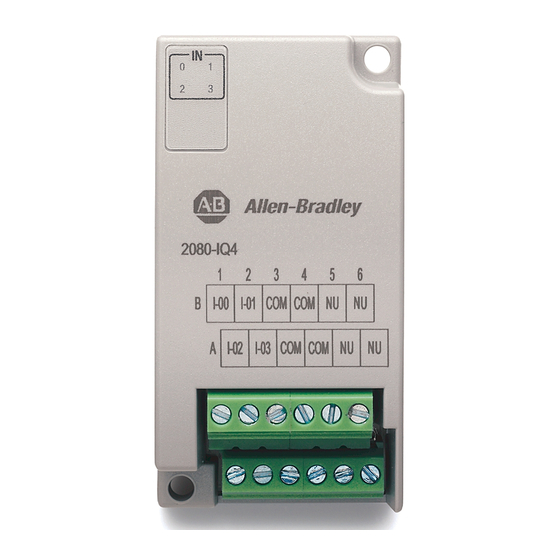
- Page 9 • Add additional communication functionality. Micro820, Micro830, and Micro850 support the following plug-in modules: Micro800 Plug-in Modules Module Type Description 2080-IQ4 Digital 4-point, 12/24V DC Sink/Source input 2080-IQ4OB4 Digital 8-point, Combo, 12/24V DC Sink/Source input 12/24V DC Source output...
-
Page 10: Digital Plug-Ins
2080-MEMBAK-RTC module which can only be installed on the leftmost plug-in slot. Digital Plug-ins 12/24V Digital Plug-ins — 2080-IQ4, 2080-IQ4OB4, 2080-IQ4OV4, 2080-OB4, 2080-OV4 These digital plug-in modules provide transistor outputs for switching a variety of 12/24V DC voltages to field loads and for detecting 12/24V signals from field devices. -
Page 11: Ac/Dc Relay Output Module - 2080-Ow4I
Micro800 Plug-in Modules Chapter 1 AC/DC Relay Output Module — 2080-OW4I The 2080-OW4I is a 4-channel relay output and provides dry contact relay closure outputs for switching a variety of AC and DC voltages to field loads. Analog Plug-ins The following analog plug-ins are supported by most Micro800 controllers. Non-isolated Unipolar Analog Input and Output —... -
Page 12: Six-Channel Trimpot - 2080-Trimpot6
Chapter 1 Micro800 Plug-in Modules Status Indicators State Description Solid red (2 s) Startup cycle test in progress. Flashing red Back up in progress. Solid red (continuous) Battery low. Project Backup and Restore The project can be backed up and restored using Connected Components Workbench software. -
Page 13: Devicenet Scanner - 2080-Dnet20
Micro800 Plug-in Modules Chapter 1 as well as for communications over long cable lengths. Depending on the application and baud rate setting, you can extend this length. 2080-SERIALISOL is suitable for communication over longer cable length IMPORTANT of up to 1000 m using RS485, with up to 19200 bps baud rate. The electrical characteristics of cable used and good wiring practices are very critical in achieving reliable communication performance over longer cable length. - Page 14 Chapter 1 Micro800 Plug-in Modules Notes: Rockwell Automation Publication 2080-UM004C-EN-E - March 2015...
-
Page 15: Hardware Features
Chapter Install and Wire Your Module This chapter provides hardware features, installation, and wiring connection diagrams for all the Micro800 plug-in modules. Hardware Features The plug-in modules, except for the 2080-MEMBAK-RTC, can be plugged into any plug-in slots on the Micro800 controllers. Measurements in millimeters (inches) 2080-RTD2 shown 31.5... -
Page 16: Wiring
For longer cable length requirements, use the 2085 expansion I/O modules instead. Wiring The following plug-in modules have 12-pin Back female terminal blocks: • 2080-IQ4, • 2080-IQ4OB4, 2080-IQ4OV4 • 2080-OB4, 2080-OV4, 2080-OW4I • 2080-IF2, 2080-IF4 Front • 2080-TC2, 2080-RTD2... - Page 17 Install and Wire Your Module Chapter 2 The following plug-in modules have eight-pin female terminal blocks: • 2080-OF2 • 2080-SERIALISOL • 2080-MOT-HSC Pin Designations for 8-Pin Female Terminal Block Modules (1) (2) Back 2080-OF2 2080-SERIALISOL 2080-MOT-HSC RS485 B+ RS232 RTS Front Eight-pin female terminal block RS232 CTS...
- Page 18 Chapter 2 Install and Wire Your Module Serial Port to Modem Cable Pinout When connecting Micro800 to a modem using an RS-232 cable, the maximum that the cable length may be extended is 15.24 m (50 ft). DTE Device DCE Device (Micro800 RS232 (Modem, and Isolated Serial Port...
- Page 19 Install and Wire Your Module Chapter 2 2080-DNET20 – 6-pin Female Terminal Block Color Chips (dots) DeviceNet Port Pinout Red Dot V+ (RED) White Dot CANH (WHITE) Blue Dot SHIELD Black Dot CANL (BLUE) V- (BLACK) 10-position Plug 5-position Plug 10-position Linear Plug DeviceNet...
-
Page 20: Wiring Considerations And Applications For 2080-Tc2
Chapter 2 Install and Wire Your Module Wiring Considerations and Type of CJC Sensor Applications for 2080-TC2 The CJC sensor is a non-polarized, passive negative temperature co-efficient thermistor (EPCOS B57869S0502F140). It is readily available in the market 2.41 max with most third party suppliers/vendors. CJC Channel Error 6.5 max IMPORTANT... -
Page 21: Wiring Considerations And Applications For 2080-Rtd2
Install and Wire Your Module Chapter 2 Direct sensor wiring Shielded/sheathed thermocouple sensor 2080-TC2 Cable tray/conduit Blue Green Blue 1 2 3 4 5 6 1 2 3 4 5 6 Process temperature measurement 45790 ATTENTION: Direct wiring is the preferred method of wiring for thermocouples. -
Page 22: Wire The Rtd Module And Rtd Sensor In The Field
Chapter 2 Install and Wire Your Module Wire the Sensors Ch0+ Ch0+ Ch0+ white white white green Ch1+ Ch0- Ch0- Ch1- black Ch1L Ch0L black Ch0L Ch0- 2-wire sensor 3-wire single Ch0L connection 45778 sensor connection 3-wire dual sensor connection NOTE: This illustration provides for channel 0 only for 2- and 3- wire single sensor connections. - Page 23 Install and Wire Your Module Chapter 2 Cabling used with the 2080-TC2/RTD2 modules have to be shielded IMPORTANT twisted cores with the shield wire shorted to chassis ground at controller end. It is advisable to use 22 AWG wires to connect the sensors to the module.
-
Page 24: Wiring Applications For 2080-Mot-Hsc
Chapter 2 Install and Wire Your Module Wiring Applications for The following diagrams show wiring applications for the 2080-MOT-HSC plug-in with Kinetix® Servo drives. 2080-MOT-HSC Kinetix 3 in feedback configuration to 2080-MOT-HSC Micro830/Micro850 QBB (24 pts) I/O Connector 49 = 24V_PULS+ 12 = PLUS- 14 = SIGN- 25 = 24V_SIGN+... - Page 25 Install and Wire Your Module Chapter 2 Micro830/Micro850 QBB (24 pts) I/O Connector 49 = 24V_PULS+ 12 = PLUS- 14 = SIGN- 25 = 24V_SIGN+ FEEDBACK I/O Connector 29 = AM+ 30 = AM- 31 = BM+ 32 = BM- Rockwell Automation Publication 2080-UM004C-EN-E - March 2015...
- Page 26 Chapter 2 Install and Wire Your Module Notes: Rockwell Automation Publication 2080-UM004C-EN-E - March 2015...
-
Page 27: Thermocouple Module
Chapter Non-isolated Thermocouple and RTD Plug-in Modules – 2080-TC2 and 2080-RTD2 The Thermocouple (2080-TC2) and RTD (2080-RTD2) plug-in modules allow for temperature measure and control when used with PID. This plug-in can be used in any slot of your Micro830/Micro850 controller. Removal and Insertion Under Power (RIUP) is not supported. -
Page 28: Rtd Module
Appendix 3 Non-isolated Thermocouple and RTD Plug-in Modules – 2080-TC2 and 2080-RTD2 Thermocouple Sensor Types and Temperature Ranges Thermocouple Temperature Range Accuracy ADC Update Type ° C (°F) ° C (°F) Rate in Hz (Accuracy °C) ±1.0 °C ±3.0 °C 40 (104) 1820 90…1700... -
Page 29: Connected Components Workbench Global Variables
Non-isolated Thermocouple and RTD Plug-in Modules – 2080-TC2 and 2080-RTD2 Appendix 3 It supports two- and three-wire type of RTD sensor wiring. RTD Compatibility An RTD consists of a temperature-sensing element connected by two, three, or four wires that provide resistance input to the module. The following table lists the RTD types that you can use with the module, including their temperature range, accuracy, and ADC update rate. -
Page 30: Data Maps
Appendix 3 Non-isolated Thermocouple and RTD Plug-in Modules – 2080-TC2 and 2080-RTD2 Connected Components The following bit/words describe the information read from the Thermocouple and RTD plug-in modules in the Connected Components Workbench Global Workbench Global Variables. Variables Data Maps Mapping Table Word Offset 00 (example: _IO_P1_AI_00) -
Page 31: Temperature Conversion - Data To Degree Celsius (°C)
Non-isolated Thermocouple and RTD Plug-in Modules – 2080-TC2 and 2080-RTD2 Appendix 3 Temperature Conversion – Data to Degree Celsius (°C) To keep the precision of temperature value from the Thermocouple and RTD plug-in modules, there is a general data mapping conversion in the firmware before the actual temperature is sent to the Connected Components Workbench software. - Page 32 Appendix 3 Non-isolated Thermocouple and RTD Plug-in Modules – 2080-TC2 and 2080-RTD2 Notes: Rockwell Automation Publication 2080-UM004C-EN-E - March 2015...
-
Page 33: Overview
Chapter High Speed Counter – 2080-MOT-HSC Overview The 2080-MOT-HSC plug-in module provides enhanced high speed counter capabilities to the Micro800 controller. It supports the same functionalities of an embedded high-speed counter on the Micro800 controllers but is enhanced to support up to 250 KHz 5V differential line driver for improved noise immunity and provides additional dedicated I/O. -
Page 34: Number Of Counters: 1 To 2
Appendix 4 High Speed Counter – 2080-MOT-HSC Nominal Filter Settings Maximum Guaranteed Minimum Guaranteed Pass Block Pulse Width Pulse Width 80 kHz (DC 6.25 μs) 128 kHz (DC 3.9 μs) 86.7 kHz (DC 5.8 μs) 40 kHz (DC 12.5 μs) 62.8 kHz (DC 8.0 μs) 42.5 kHz (DC 11.6 μs) 13.3 kHz (DC 35 μs) -
Page 35: Up Counter
High Speed Counter – 2080-MOT-HSC Appendix 4 Input Operational Modes Mode Description Up Counter – The accumulator is immediately cleared (0) when it reaches the high preset. A low preset cannot be defined in this mode. Up Counter with external reset and hold – The accumulator is immediately cleared (0) when it reaches the high preset. -
Page 36: Counter With External Direction
Appendix 4 High Speed Counter – 2080-MOT-HSC Counter with External Direction Pulses on A cause the counter to increment when B is low and decrement when B is high. When B is open or undriven, the counter will increment. See Pulse External Direction Counting on page Pulse External Direction Counting... - Page 37 High Speed Counter – 2080-MOT-HSC Appendix 4 Incrementing Increment Pulse INPUT A Encoder or Sensor (count up) INPUT B Decrement Pulse Decrementing Encoder or Sensor (count down) INPUT Z Increment Pulse (Input A) Count Pulse (Input A) Present Count Up/Down Counting Change in Count Value 0 or 1 0 or 1...
- Page 38 Appendix 4 High Speed Counter – 2080-MOT-HSC Quadrature Counting INPUT A Quadrature INPUT B Encoder INPUT Z Count Count 11 12 10 9 Quadrature X4 Counter Counter shall increment or decrement on each edge of the A and B pulses when the signal is in the positive or negative direction respectively.
- Page 39 High Speed Counter – 2080-MOT-HSC Appendix 4 Down Counting Decrement Pulse Encoder or Sensor INPUT A (count down) INPUT B Decrement Pulse Encoder or Sensor (count down) INPUT Z Counter 0 (Input A) PresentCount 1 Counter 0 (Input B) PresentCount 2 Z Input (Gate) Function/Touch Probe This signal functionality supports: •...
- Page 40 Appendix 4 High Speed Counter – 2080-MOT-HSC flag will be set to indicate that a rollunder has occurred. It is reset using the ResetCountUnderflow_n bit. MinCountValue MaxCountValue Rollover Count Down Count Up 1: linear counter. When the counter is a linear counter and the present count value is equal to MaxCountValue_n the next input count in the up direction will activate the CountOverflow_n bit and also the PresentCount_n will remain at the MaxCountValue_n.
-
Page 41: Understanding Rates
High Speed Counter – 2080-MOT-HSC Appendix 4 MinCountValue MaxCountValue Count Up Count Down Underflow Overflow Enabling and Disabling a Counter using the HSC_EN bit Disabling the counter does not inhibit any HSC_ACC_Bn loading functions (preset or direct write) or any Z function. The module continuously calculates rates for each of the counters regardless of input operational mode. - Page 42 Appendix 4 High Speed Counter – 2080-MOT-HSC Per Pulse The Per Pulse rate method can be very accurate if the time between pulses is large compared to the timer clock (1 μs for 2080-MOT-HSC). A timer is used to measure the time between the two successive pulses. This value is reported to the backplane as HSC_PULSE_WIDTH_Bn after each pulse.
-
Page 43: User Defined Function Blocks
High Speed Counter – 2080-MOT-HSC Appendix 4 Per Pulse Errors Real pulses Pulses Real Reported % Error (note 1.9999 can reported by Frequency Frequency be rounded to 2) module 1001 1000 999 Hz 1000 Hz 0.10% 9,999 10,000 100.01 Hz 100.00 Hz 0.010% 99,999... - Page 44 Appendix 4 High Speed Counter – 2080-MOT-HSC RA_HSCPlugIn: Input and Output Parameters Parameter Type Data Type Description FBEN INPUT BOOL Function block Enable input SlotID INPUT UINT Plug-in slot number. Slot ID = 1…5 (starting with the far left slot 1.) NoiseFilter INPUT USINT...
- Page 45 High Speed Counter – 2080-MOT-HSC Appendix 4 RA_EncoderFDBK: Input and Output Parameters Parameter Type Data Description Type NoiseFilter INPUT USINT 00 - No filter 01 - 250 kHz 02 - 200 kHz 03 - 80 kHz 04 - 40 kHz 05 - 13.3 kHz 06 - 10 kHz 07 - 4 kHz...
-
Page 46: Use The 2080-Mot-Hsc Module
Appendix 4 High Speed Counter – 2080-MOT-HSC RA_ServoFDBK: Input and Output Parameters Parameter Type Data Description Type NoiseFilter INPUT USINT 00: No filter 01: 250 kHz 02: 200 kHz 03: 80 kHz 04: 40 kHz 05: 13.3 kHz 06: 10 kHz 07: 4 kHz 08: 2 kHz 09: 1 kHz... -
Page 47: Overview
Chapter DeviceNet Plug-in – 2080-DNET20 Overview The DeviceNet plug-in serves as scanner and client for explicit messaging to remote devices. The module is designed to scan devices such as: • CompactBlock™ LDX • PowerFlex® drives • E1Plus overloads • stack lights User-defined function blocks (UDFB) are required to enable interaction between these devices. -
Page 48: Network Configuration
Appendix 5 DeviceNet Plug-in – 2080-DNET20 Module Status Indicator LED state Module status Description No power There is no power present. Flashing Green Operational Unit is starting up. Green Unit operational Device is operating normally. Flashing Red Minor fault. A recoverable fault is present or the module is undergoing firmware update. -
Page 49: Devicenet Switches
DeviceNet Plug-in – 2080-DNET20 Appendix 5 Maximum power supply drop cable length is 3 m. IMPORTANT Recommended Cable Flat Cable (Kwiklink lite) – Class 1 cable maximum allowable current 8A (NEC/CECode) – Class 2 cable maximum allowable current 4A (NEC/CECode) DeviceNet Switches 2080-DNET20 Assembly Diagram Dim A... -
Page 50: Power Supply
Appendix 5 DeviceNet Plug-in – 2080-DNET20 DeviceNet Baud Rate Switch Definitions Baud Rate DR (Data Rate) SW1 Switch Position 125k 250k 500k (default) Autobaud For most applications, Rockwell Automation recommends that you use IMPORTANT default node and baud rate settings. The DeviceNet scanner plug-in will be at node 0 and the devices will be at nodes 1...20. - Page 51 DeviceNet Plug-in – 2080-DNET20 Appendix 5 If two or more power supplies are connected to the Kwinklink lite media (trunk cable) V+ should be broken between the two power supplies. CAN_H CAN_L V+ broken between power supplies Power Supply Power Supply only one ground Enclosure Grounding the network...
- Page 52 Appendix 5 DeviceNet Plug-in – 2080-DNET20 Single Source Power Supply – Trunkline Length and Maximum Current 120 (394) 2.39 340 (1115) 0.85 140 (459) 2.05 360 (1181) 0.80 160 (525) 1.79 380 (1247) 0.76 180 (591) 1.60 400 (1312) 0.72 200 (656) 1.44 420 (1378)
-
Page 53: User Defined Function Blocks
DeviceNet Plug-in – 2080-DNET20 Appendix 5 Calculate Voltage Requirement SUM {[(Ln * (Rc)) + (Nt * (0.005))] * In} < 4.65 V Where: Ln = Length in meter or feet Rc = Resistance of the cable per meter or feet (Kwiklink flat media = 0.019 ohms/meter or 0.0058/feet) Nt = Number of the node starting from 1 close to power supply and increasing. -
Page 54: Ra_Dnet_Node_Status
Appendix 5 DeviceNet Plug-in – 2080-DNET20 RA_DNET_MASTER: Input and Output Parameters Variable Name Type Data Type Description Error OUTPUT STRING Scanner error description. ActiveNodes OUTPUT USINT Number of slave nodes in the network. Scanlist0_62 OUTPUT LWORD Details on active node table, bit 0…62. Bit 0: Represent Node 0. -
Page 55: Ra_Dnet_Ldx_Discrete
DeviceNet Plug-in – 2080-DNET20 Appendix 5 RA_DNET_NODE_STATUS: Input and Output Parameters Variable Name Type Data Type Description FBEN INPUT BOOL Function block enable input. TRUE to enable the function. SlotID INPUT UINT Plug-in slot number (1…5) NodeID INPUT USINT Slave node address. FBENO OUTPUT BOOL... -
Page 56: Ra_Dnet_Ldx_Analog
Appendix 5 DeviceNet Plug-in – 2080-DNET20 RA_DNET_LDX_DISCRETE: Input and Output Parameters Variable Name Type Data Type Description Module3 INPUT STRING Expansion module 2 I/O configuration. INPUT X OUTPUT Channels For example: 16X0 (16 input / 0 Output is physically present as base module) Valid String: 32X0, 0X32, 16X0, 0X16, 16X16, 8X8, 8X0, 0X8, 0X6 NOTE: X should always be upper case. -
Page 57: Ra_Dnet_Ldx_Tc_Rtd
DeviceNet Plug-in – 2080-DNET20 Appendix 5 RA_DNET_LDX_ANALOG: Input and Output Parameters Variable Name Type Data Type Description Module3 INPUT STRING Digital expansion module 2 I/O configuration. INPUT X OUTPUT channels For example: 16X16 (16 input / 16 output is physically present as expansion module 2) Valid String: 16X0, 0X16, 16X16, 8X8, 8X0, 0X8, 0X6 NOTE: X should always be upper case. -
Page 58: Ra_Pf_Dnet_Standard
Appendix 5 DeviceNet Plug-in – 2080-DNET20 RA_DNET_LDX_TC_RTD: Input and Output Parameters Variable Name Type Data Type Description OUTPUT WORD RTD/Thermocouple input channel 2 value. OUTPUT WORD RTD/Thermocouple input channel 3 value. StatusCH0_3 OUTPUT WORD RTD/Thermocouple Input channel 0…3 status. RA_DNET_TOWERLIGHT RA_DNET_TOWERLIGHT FBEN FBENO... -
Page 59: Ra_Pf_Dnet_Multidrive
DeviceNet Plug-in – 2080-DNET20 Appendix 5 RA_PF_DNET_STANDARD: Input and Output Parameters Variable Name Type Data Type Description Status OUTPUT BOOL PowerFlex drive status. PF_Feedback OUTPUT REAL Feedback from the PowerFlex drive. PF_ErrorCode OUTPUT For future use. PF_Ready OUTPUT BOOL Ready bit from PowerFlex drive. PF_Active OUTPUT BOOL... - Page 60 Appendix 5 DeviceNet Plug-in – 2080-DNET20 RA_PF_DNET_MULTIDRIVE: Input and Output Parameters Variable Name Type Data Type Description FBEN INPUT BOOL Function block enable input. TRUE to enable the function. PlcPortNum INPUT UINT Plug-in slot number (1…5 for plug-in slots). NodeNum INPUT USINT DeviceNet node address for PowerFlex drive...
-
Page 61: Ra_Dnet_Overload
DeviceNet Plug-in – 2080-DNET20 Appendix 5 RA_PF_DNET_MULTIDRIVE: Input and Output Parameters Variable Name Type Data Type Description PF_Alarm OUTPUT BOOL[1...5] Alarm bit from PowerFlex drive. Each element of the array corresponds to each drive, for example, PF_Alarm[1] for Drive 1 and PF_Alarm[5] for Drive5. - Page 62 Appendix 5 DeviceNet Plug-in – 2080-DNET20 RA_DNET_GENERIC: Input and Output Parameters Variable Name Type Data Type Description FBEN INPUT BOOL Function block enable input. TRUE to enable function. SlotID INPUT UINT Plug-in slot number (1…5 for plug-in slots). NodeID INPUT USINT Slave node address.
- Page 63 DeviceNet Plug-in – 2080-DNET20 Appendix 5 Transaction Block Format Byte Offset Contents Status Transaction ID Size Reserved MAC ID Service 6…115 Transaction Body (110 bytes) Explicit Message Request Format Byte Offset Contents Status Transaction ID Size Reserved MAC ID Service 6…7 Class 8…9...
-
Page 64: Through
Appendix 5 DeviceNet Plug-in – 2080-DNET20 Explicit Message Status Codes Transaction completed successfully. Transaction in progress (not ready). Error – node offline Error – DeviceNet port disabled/offline Error – Transaction TXID unknown Error – Duplicate TXID Error – Scanner out of buffers Error –... -
Page 65: Error Codes
DeviceNet Plug-in – 2080-DNET20 Appendix 5 • Using MSG_CIPGENERIC starting from Micro850, the Slave device cannot be accessed because the MSG_CIPGENERIC target path configuration is limited to a single hop. This path will work if you use a Logix controller/PC instead of Micro850. Note that the number “4”... -
Page 66: Use The 2080-Dnet20 Plug-In
Appendix 5 DeviceNet Plug-in – 2080-DNET20 DeviceNet plug-in Error Codes and Descriptions ErrorID Description User has disabled scanner. Bus Off detected on scanner. No network power detected. CRC failure detected on one or more configuration blocks. Scanner application program flash is being updated. Port is in test mode. -
Page 67: Digital Plug-In Modules
Appendix Specifications Digital Plug-in Modules General Specifications – 2080-OB4, 2080-OV4, 2080-IQ4OB4, 2080-IQ4OV4, 2080-IQ4 Attribute Value Mounting torque 0.2 Nm (1.48 lb-in.) Status indicators For input or output modules – 4 yellow For combination modules – 8 yellow Terminal base screw torque 0.22…0.25 Nm (1.95…2.21 lb-in.) - Page 68 Appendix A Specifications Input Specifications – 2080-IQ4, 2080-IQ4OV4, 2080-IQ4OB4 Attribute Value AC on-state current, min 2.0 mA @ 9V AC (rms) AC on-state current, max 5.0 mA AC off-state voltage 3.5V AC (rms) Output Specifications – 2080-OB4, 2080-OV4, 2080-IQ4OB4, 2080-IQ4OV4...
- Page 69 Surge transient immunity ±1 kV line-line(DM) and ±2 kV line-earth(CM) on signal ports Conducted RF immunity 10V rms with 1 kHz sine-wave 80%AM from 150 kHz…80 MHz Certifications – 2080-OB4, 2080-OV4, 2080-IQ4OB4, 2080-IQ4OV4, 2080-IQ4 Certification (when Value product is marked) c-UL-us UL Listed Industrial Control Equipment, certified for US and Canada.
- Page 70 Appendix A Specifications General Specifications – 2080-OW4I Digital Relay Output Plug-in Module Attribute Value Backplane power 3.3 VDC, 38 mA Output current, resistive 2 A @ 5…30V DC 0.5 A @ 48V DC 0.22 A @ 125V DC 2 A @ 125V AC 2 A @ 240V AC Output current, inductive 1.0 A steady state @ 5…28V DC...
- Page 71 Specifications Appendix A Environmental Specifications – 2080-OW4I Attribute Value Shock, non-operating IEC 60068-2-27 (Test Ea, Unpackaged Shock): DIN rail mounting: 25 g Panel mounting: 35 g ESD Immunity IEC 61000-4-2: 6kV contact 8 kV air Radiated RF immunity IEC 61000-4-3 10 V/M with 1 kHz sine-wave 80%AM from 80…2000 MHz 10 V/M with 200 Hz sine-wave 50% Pulse 100%AM @ 900 MHz 10 V/M with 200 Hz sine-wave 50% Pulse 100%AM @1890 MHz...
-
Page 72: Analog Plug-In Modules
Appendix A Specifications Analog Plug-in Modules Input Specifications – 2080-IF2, 2080-IF4 Attribute 2080-IF2 2080-IF4 Number of inputs, single ended Analog normal operating ranges Voltage: 0…10V DC Current: 0…20 mA Resolution, max. 12 bits unipolar, with software selected option for 50 Hz, 60 Hz, 250 Hz, 500 Hz Data range... - Page 73 Specifications Appendix A Output Specifications – 2080-OF2 Attribute 2080-OF2 Step Response to 63% 5 ms Current Load ln voltage output, max 10 mA 0…500 Ω (includes wire resistance) Resistive load on current output > 1k Ω @ 10V DC Load range on voltage output Max.
-
Page 74: Specialty Plug-In Modules
Appendix A Specifications Certifications – 2080-IF2, 2080-IF4, 2080-OF2 Certification (when Value product is marked) c-UL-us UL Listed Industrial Control Equipment, certified for US and Canada. See UL File E322657. UL Listed for Class I, Division 2 Group A,B,C,D Hazardous Locations, certified for U.S. - Page 75 Specifications Appendix A Specifications – 2080-TRIMPOT6 Attribute Value Data range 0…255 Number of trimpot Temperature, operating IEC 60068-2-1 (Test Ad, Operating Cold), IEC 60068-2-2 (Test Bd, Operating Dry Heat), IEC 60068-2-14 (Test Nb, Operating Thermal Shock): -20...65 °C (-4…149 °F) Temperature, nonoperating IEC 60068-2-1 (Test Ab, Unpackaged Nonoperating Cold), IEC 60068-2-2 (Test Bb, Unpackaged Nonoperating Dry Heat),...
- Page 76 Appendix A Specifications General and Environmental Specifications – 2080-TC2, 2080-RTD2 Attribute 2080-RTD2 2080-TC2 CJC error — ±1.2 °C @ 25 °C (77 °F) Accuracy ±1.0 °C for TC and RTD @ 25 °C (77 °F) Channels 2, non-isolated 100 Ω Platinum 385 RTD types supported —...
- Page 77 Specifications Appendix A General Specifications – 2080-MOT-HSC Attribute Value Dimensions, HxWxD, approx. 62 x 31.5 x 20 mm (2.44 x 1.24 x 0.79 in.) Terminal screw torque 0.22…0.25 Nm (1.95…2.21 lb-in.) using a 2.5 mm (0.10 in.) flat-blade screwdriver Bus current draw 60 mA @ 3.3V DC Recommended cable Individually shielded, twisted-pair cable (or the type recommended...
- Page 78 Appendix A Specifications (1) Phase separation is the recognition of phase time of A input and B input. Input A Input B Phase separation Output Specifications – 2080-MOT-HSC Attribute Value Number of outputs 16 (1 physical output; 15 virtual) Output voltage range 5…30V DC Output on-state current, max 0.5 A...
- Page 79 Specifications Appendix A Maximum output voltage – 24V DC operation Voltage Derating Based on Temperature 26.4V DC @ 65 °C Ambient Temperature (°C) Maximum output currrent per point – 5V DC operation Current Derating Based on Temperature Ambient Temperature (°C) Maximum output current per point –...
- Page 80 Appendix A Specifications Environmental Specifications – 2080-MOT-HSC Attribute Value Temperature, operating IEC 60068-2-1 (Test Ad, Operating Cold), IEC 60068-2-2 (Test Bd, Operating Dry Heat), IEC 60068-2-14 (Test Nb, Operating Thermal Shock): -20…65 °C (-4…149 °F) Temperature, nonoperating IEC 60068-2-1 (Test Ab, Unpackaged Nonoperating Cold), IEC 60068-2-2 (Test Bb, Unpackaged Nonoperating Dry Heat), IEC 60068-2-14 (Test Na, Unpackaged Nonoperating Thermal Shock):...
-
Page 81: Communication Plug-In Modules
Specifications Appendix A Certifications – 2080-MOT-HSC Certification (when Value product is marked) c-UL-us UL Listed Industrial Control Equipment, certified for US and Canada. See UL File E322657. UL Listed for Class I, Division 2 Group A,B,C,D Hazardous Locations, certified for U.S. and Canada. See UL File E334470. EN 61326-1;... - Page 82 Appendix A Specifications Torque Specifications for the 2080-DNET20 Plug-in Module Mounting torque: Mounting torque 0.2 Nm 0.5…0.6 Nm Mounting torque 0.3 Nm 46209 ATTENTION: To comply with CE Low Voltage Directive (LVD), this equipment and all connected I/O must be powered from a source compliant with the following: Safety Extra Low Voltage (SELV) or Protected Extra Low Voltage (PELV).
- Page 83 Specifications Appendix A Environmental Specifications – 2080-DNET20 Attribute Value EFT/B immunity IEC 61000-4-4: ±4 kV @ 5 kHz on power ports ±2 kV @ 5 kHz on communication ports Surge transient immunity IEC 61000-4-5: ±1 kV line-line(DM) and ±2 kV line-earth(CM) on power ports ±2 kV line-earth(CM) on communication ports Conducted RF immunity IEC 61000-4-6:...
- Page 84 Appendix A Specifications Certifications – 2080-DNET20 Certification (when product Value is marked) c-UL-us UL Listed Industrial Control Equipment, certified for US and Canada. See UL File E322657. UL Listed for Class I, Division 2 Group A,B,C,D Hazardous Locations, certified for U.S. and Canada. See UL File E334470. EN 61326-1;...
- Page 85 Specifications Appendix A Certifications – 2080-SERIALISOL Certification (when product Value is marked) c-UL-us UL Listed Industrial Control Equipment, certified for US and Canada. See UL File E322657. UL Listed for Class I, Division 2 Group A,B,C,D Hazardous Locations, certified for U.S. and Canada. See UL File E334470. European Union 2004/108/EC EMC Directive, compliant with: EN 61326-1;...
- Page 86 Appendix A Specifications Notes: Rockwell Automation Publication 2080-UM004C-EN-E - March 2015...
-
Page 87: Add And Configure Plug-Ins In Connected Components Workbench
Appendix Quickstart This chapter provides the following quickstarts. Topic Page Add and Configure Plug-ins in Connected Components Workbench Browse Your 2080-DNET20 Plug-in Using RSLinx Flash Upgrade Your 2080-DNET20 Plug-in Firmware Quickstart Project for 2080-DNET20 Plug-in Quickstart Projects for 2080-MOT-HSC Plug-in Add and Configure Plug-ins This section shows you an example of how to configure the plug-ins through the Connected Components Workbench software. - Page 88 Appendix B Quickstart The Controller Properties page appears. 2. To add a Micro800 plug-in, you can do any of the following: • Right-click the plug-in slot you would like to configure and choose the plug-in, as shown below. Rockwell Automation Publication 2080-UM004C-EN-E - March 2015...
-
Page 89: Browse Your 2080-Dnet20 Plug-In Using Rslinx
Quickstart Appendix B • Right-click the plug-in slot in the Controller Properties tree and choose the plug-in you would like to add. The device configuration window should show the added plug-in modules: Browse Your 2080-DNET20 There are two methods you can use to browse for your 2080-DNET20 plug-in using RSLinx. -
Page 90: Browse Using The Devicenet Network
Appendix B Quickstart Browse Using the DeviceNet Network From the computer, the 2080-DNET20 plug-in can be browsed through the DeviceNet network. This requires an additional device to connect the computer to the DeviceNet network. For example, you can use the 1788-EN2DN or 1784-U2DN devices. -
Page 91: Browse Using The Micro800 Pass Through
Quickstart Appendix B Browse Using the Micro800 Pass Through To use the controller pass through feature, the following firmware IMPORTANT revisions are required: • Micro820/Micro830/Micro850 controller firmware revision 8.011 or higher. • 2080-DNET20 plug-in firmware revision 2.011 or higher. Browsing the 2080-DNET20 plug-in from the controller backplane through EtherNet/IP. -
Page 92: Rockwell Automation Publication 2080-Um004C-En-E - March
Appendix B Quickstart Browsing the 2080-DNET20 plug-in from the controller backplane through Serial DF1. Flash Upgrade Your This quick start will show you how to flash update the firmware in a 2080-DNET20 plug-in using ControlFLASH. ControlFLASH is installed or 2080-DNET20 Plug-in updated when Connected Components Workbench software is installed on your Firmware computer. - Page 93 Quickstart Appendix B 2. Launch ControlFLASH and click Next. 3. In the Catalog Number dialog, select the 2080-DNET20 plug-in and click Next. Rockwell Automation Publication 2080-UM004C-EN-E - March 2015...
- Page 94 Appendix B Quickstart 4. The Connection Browser dialog appears, select the 2080-DNET20 plug- in and click OK. To upgrade from firmware revision 1.012 to 2.011, the DeviceNet IMPORTANT network should be used. From revision 2.011 onwards, you can upgrade the firmware using the controller pass through feature. 5.
- Page 95 Quickstart Appendix B 6. Verify your selection and click Finish. 7. Click Yes to continue. 8. Click OK to begin the upgrade process. A dialog showing the progress appears. Rockwell Automation Publication 2080-UM004C-EN-E - March 2015...
-
Page 96: 2080-Dnet20 Plug-In
Appendix B Quickstart 9. When the flash update is complete, the Update Status dialog appears. Check that the status is green and the update is complete. If the status is unsuccessful, power cycle the controller and restart the upgrade process. 10. -
Page 97: Setup And Wiring
Quickstart Appendix B Setup and Wiring 1. Insert your 2080-DNET20 module into the designated plug-in slot in your Micro800 controller. 2. Next, wire your 2080-DNET20 plug-in following the diagram shown below. Color Chips (dots) DeviceNet Port Pinout Red Dot V+ (RED) White Dot CANH (WHITE) Blue Dot... -
Page 98: Configuration
Appendix B Quickstart 3. Configure the DeviceNet devices as shown below. Micro800 controller CompactBlock LDX COMM power supply PowerFlex 523 1 KwikLink Lite IP20 Flat Media with 2 Trunk Line Connector Component on 25-COMM-D 3 Drop Line Connector DeviceNet 4 Terminating Resistor Network 5 5-pin Open Style Connector 6 Power Tap with terminating resistor... - Page 99 Quickstart Appendix B 3. Configure the RA_DNET_MASTER UDFB as shown. 4. Configure the PowerFlex UDFB as shown (that is, set the node address, plug-in slot ID, and so on). Rockwell Automation Publication 2080-UM004C-EN-E - March 2015...
-
Page 100: Build And Download
Appendix B Quickstart 5. Configure the CompactBlock LDX UDFB as shown (that is, set the node address, plug-in slot ID, Module1…Module4). Build and Download Build and download the project into the controller. Rockwell Automation Publication 2080-UM004C-EN-E - March 2015... -
Page 101: Execute Program
Quickstart Appendix B Execute Program 1. Set Micro800 controller to RUN mode. 2. Enable AutoScan in the DeviceNet Scanner UDFB. This will scan all the active nodes and populate the scan list. 3. Set the Scanner to RUN mode. It is recommended that when Autoscan is running for the nodes in IMPORTANT range, or for the connection to be established, the nodes should be idle without any pre-occupied connections requests. -
Page 102: Setup And Wiring
Appendix B Quickstart Setup and Wiring 1. Insert the high speed counter plug-in module into the designated slot in your Micro800 controller. 2. Wire your plug-in to your controller as shown in the following diagram. Back (View into terminal block) Pin A1 0- Pin B1 0+ Pin A2 A-... -
Page 103: Configuration For Udfb 1: Ra_Hscplugin
Quickstart Appendix B Configuration for UDFB 1: RA_HSCPlugIn NOTE: The purpose of this UDFB is to get high speed counter accumulator value and current pulse frequency. 1. Launch Connected Components Workbench. Open the sample project you have downloaded from the Sample Code Library. 2. -
Page 104: Build And Download
Appendix B Quickstart Input and Output Parameters Parameter Type Data Type Description Initialized OUTPUT BOOL TRUE: HSC plug-in initialization finished and ready to execute. FALSE: HSCplug-in initialization not yet finished. Accumulator OUTPUT LINT Accumulator value. Rate OUTPUT Real Current pulse rate. The rate calculation is based on how many pulses have been counted every 10 ms. -
Page 105: Configuration For Udfb 2: Ra_Encoderfdbk
Quickstart Appendix B • If FBEN is True and the user starts the feedback process from previous Stop state, the function block will not be reinitialized. It will resume count from previous accumulator value. • IF FBEN is False, then all outputs are cleared and accumulator is cleared. When FBEN goes True again , the HSC will be reinitialized. -
Page 106: Build And Download
Appendix B Quickstart Input and Output Parameters Parameter Type Data Description Type NoiseFilter INPUT USINT 00 - No filter 01 - 250 kHz 02 - 200 kHz 03 - 80 kHz 04 - 40 kHz 05 - 13.3 kHz 06 - 10 kHz 07 - 4 kHz 08 - 2 kHz 09 - 1 kHz... -
Page 107: Execute The Function Block
Quickstart Appendix B Execute the Function Block Operation Sequence • A rising edge of FBEN will cause the function block Start initialize steps. When initialized done, Output Initialized will change to TRUE. • You can start the feedback process (Start counting) after Initialized output becomes TRUE. -
Page 108: Configuration For Hsc Udfb 3: Ra_Servofdbk
Appendix B Quickstart • IF FBEN is False, then all outputs are cleared and accumulator is cleared and when FBEN goes true again, the HSC will be reinitialized. Configuration for HSC UDFB 3: RA_ServoFDBK NOTE: This UDFB gets positioning information of a PTO axis that is controlled by a Micro800 controller with HSC plug-in installed. -
Page 109: Build And Download
Quickstart Appendix B Input and Output Parameters Parameter Type Data Description Type NoiseFilter INPUT USINT 00 - No filter 01 - 250 kHz 02 - 200 kHz 03 - 80 kHz 04 - 40 kHz 05 - 13.3 kHz 06 - 10 kHz 07 - 4 kHz 08 - 2 kHz 09 - 1 kHz... -
Page 110: Execute The Function Block
Appendix B Quickstart Execute the Function Block Operation Sequence • A rising edge of FBEN causes the function block to start initializing steps. When Initialized is done, Output Initialized changes to TRUE. • You can start the feedback process (Start counting) after Initialized is TRUE. - Page 111 Quickstart Appendix B • IF FBEN is false, then all outputs are cleared and accumulator is cleared. When FBEN goes true again, the HSC will be re-initialized. Rockwell Automation Publication 2080-UM004C-EN-E - March 2015...
- Page 112 Appendix B Quickstart Notes: Rockwell Automation Publication 2080-UM004C-EN-E - March 2015...
-
Page 113: Troubleshooting
Appendix Error Codes Troubleshooting For troubleshooting your Micro800 controller system, see the User Manual for your controller: • Micro830 and Micro850 Programmable Controllers User Manual, publication 2080-UM002. • Micro820 Programmable Controllers User Manual, publication 2080-UM005. Error Codes for Micro800 This section lists possible error codes for your plug-in modules, as well as recommended actions for recovery. -
Page 114: Calling Rockwell Automation For Assistance
Appendix C Error Codes Calling Rockwell If you need to contact Rockwell Automation or local distributor for assistance, it is helpful to obtain the following (prior to calling): Automation for Assistance • controller type, series letter, revision letter, and firmware (FRN) number of the controller •... - Page 115 9 2080-IF4 3 2080-TC2 3 certifications 66 certifications 66 specifications 64 data maps 22 wiring 8 features 19 2080-IQ4 2 specifications 67 certifications 61 thermocouple sensor types and ranges 19 specifications 59 wiring 8 wiring 8 2080-TRIMPOT6 4 2080-IQ4OB4 2...
- Page 116 Index Micro800 plug-ins 1 6-channel trimpot analog input plug-in module 4 DeviceNet scanner plug-in module 5 digital I/O plug-in module 2 high speed counter plug-in module 4 memory backup and high accuracy RTC plug-in module 3 non-isolated RTD plug-in module 3 non-isolated unipolar analog I/O plug-in module 3 relay output plug-in module 3 RS232/RS485 isolated serial port plug-in module 4...
- Page 117 Rockwell Automation Publication 2080-UM004C-EN-E - March 2015...
- Page 118 Rockwell Automation Support Rockwell Automation provides technical information on the Web to assist you in using its products. At http://www.rockwellautomation.com/support/, you can find technical manuals, a knowledge base of FAQs, technical and application notes, sample code and links to software service packs, and a MySupport feature that you can customize to make the best use of these tools.
Need help?
Do you have a question about the 2080-IQ4 and is the answer not in the manual?
Questions and answers