Table of Contents
Advertisement
Quick Links
Advertisement
Table of Contents

Subscribe to Our Youtube Channel
Related Manuals for Power Measurement ION 8800


Summary of Contents for Power Measurement ION 8800
- Page 1 Installation Guide...
-
Page 3: Installation Considerations
Installation Considerations Installation and maintenance of the ION 8800 meter should only be performed by qualified, competent personnel that have appropriate training and experience with high voltage and current devices. The meter must be installed in accordance with all local and national electrical codes. -
Page 4: Standards Compliance
Regardless of whether any remedy set forth herein fails of its essential purpose, except to the extent the following limitation is prohibited by applicable law, Power Measurement shall not, in any event or under any legal claim or theory (whether based on contract, indemnity, warranty, tort (including negligence and strict liability) or... -
Page 5: Available Options
4 Form C solid-state outputs 3 High voltage Essailec connector IRIG-B Before You Begin Before installing the meter, familiarize yourself with the steps in this guide and read the safety precautions presented on the “Installation Considerations” page. © 2007 Power Measurement. All rights reserved. -
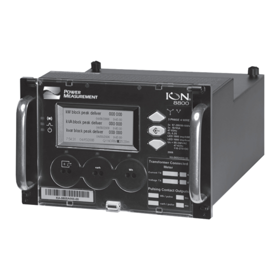
Page 6: Meter Overview
Sealed Buttons Operational LEDs Navigation Buttons Display Optical Battery Cover Communications Port Slot-head varh Cover Slot-head Pulsing Screw Pulsing Seal Screw Port Port Meter Back Communications Module Cover Plate Essailec Connector Ground Terminal © 2007 Power Measurement. All rights reserved. - Page 7 Removable User Label User Label Removable User Labels Insert user labels between bezel label and plastic lid while cover is open. 50.0 mm (1.97“) 13.0 mm (0.51“) 60.0 mm (2.36“) 44.0 mm (1.73“) © 2007 Power Measurement. All rights reserved.
-
Page 8: Unit Dimensions
260.0 mm (10.24“) 111.8 mm (4.40“) Front of Rack View 482.0 mm (18.98“) to fit 19 inch rack 132.5 mm 57.2 mm (5.22“) (2.25“) 3U high 461.0 - 469.0 mm (18.15 - 18.46“) © 2007 Power Measurement. All rights reserved. - Page 9 Order Options B/C Circuit & Pinout Diagrams This pinout drawing details the various pins on the meter side of the connector. The table below maps the pins to their corresponding inputs and outputs in the meter. © 2007 Power Measurement. All rights reserved.
- Page 10 Order Option A Circuit & Pinout Diagrams This pinout drawing details the various pins on the meter side of the connector. The table below maps the pins to their corresponding inputs and outputs in the meter. © 2007 Power Measurement. All rights reserved.
- Page 11 Digital Inputs or RS-485 Com DI2 (or RS-485 -) RS-485 - DI3 (or unused) standard Unused Power Supply N/- Power Supply neutral (-) Power Supply Inputs (AC/DC) Power Supply L/+ Power Supply line (+) © 2007 Power Measurement. All rights reserved.
- Page 12 Order Options D/E Circuit & Pinout Diagrams This pinout drawing details the various pins on the meter side of the connector. The table below maps the pins to their corresponding inputs and outputs in the meter. © 2007 Power Measurement. All rights reserved.
-
Page 13: Step 1: Mount The Meter
For typical installations, the battery should last 10 years minimum at 25ºC meter ambient operating temperature. The battery is field replaceable (see “Replacing the Battery” on page 31). © 2007 Power Measurement. All rights reserved. - Page 14 Tighten the 2 slot-head screws (M3 thread) into the front of the meter rack, to hold the meter firmly in place. Meter Essailec Rack Essailec Connector Connector ION 8800 Meter 482.6 mm (19”) Rack Slot-head Screws © 2007 Power Measurement. All rights reserved.
- Page 15 15 - 75 VDC or VAC (RMS) Hi-Voltage Input Impedance 100 kΩ Lo-Voltage Input Impedance 20 kΩ AUTION Field Hi-Pot testing to the above isolation levels is not recommended -- risk of meter damage. © 2007 Power Measurement. All rights reserved.
- Page 16 Consult your local instrument transformer expert, either at the local utility or through a vendor or supplier, to obtain CT and PT selection standards for high accuracy revenue metering applications in your regions. © 2007 Power Measurement. All rights reserved.
- Page 17 Phase 2 voltage (U2) displayed by meter is derived from phase 1 and phase 3, not measured. U2 will display a value even if no voltage is present on Phase 2. U2 values are only accurate for balanced loads. VOLTS MODE = 3W-Wye © 2007 Power Measurement. All rights reserved.
- Page 18 3-Wire Delta, 2½-Element, Direct Connection 500 V L-L max. VOLTS MODE = Delta 3-Wire Delta, 2-Element 2 PTs & 2 CTs Use PTs for voltages over 500 V L-L. VOLTS MODE = Delta © 2007 Power Measurement. All rights reserved.
- Page 19 Voltage Range Requires PTs up to 288 V L-N or 500 V L-L Wye/ Single Phase over 288 V L-N or 500 V L-L up to 500 V L-L Delta over 500 V L-L © 2007 Power Measurement. All rights reserved.
- Page 20 Step 4: Wire the Communications ION 8800 meters are equipped with one standard optical port. Other communications ports are available as options. The Communications module cover plate (found on the back of the meter) should never be removed unless a communications module is installed in its place.
- Page 21 Pin 3: Ring Pin 4: Tip Connector Type RJ11 Wire Type Part 68 compliant telephone cord Data Rate 300 bps – 56 kbps Error Correction V.42 LAPM, MNP 2-4, V.44 Data Compression V.42 bis/MNP 5 © 2007 Power Measurement. All rights reserved.
-
Page 22: Step 5: Wire The Power Supply
Step 5: Wire the Power Supply ION 8800 meter power supply connections are found on the Essailec connector. Single Phase Power Supply 85 - 240 VAC ±10% (47 - 63 Hz) Rated Inputs 110 - 270 VDC ±10% Rating... - Page 23 Transmit Delay 0 to 1,0 0,010 setting (in seconds) From serial Identifies the meter during serial Unit ID 1 to 9 999 communications number Serial Port Parity and stop bits for the port 8N1,8N2,8E1,8E2,8O1,8O2 © 2007 Power Measurement. All rights reserved.
- Page 24 Specifies TCP/IP Ethernet address None 255.255.255.255 Mask Specifies Subnet Mask 0.0.0.0 to 255.255.255.0 None 000.000.000.000 to Gateway Specifies Ethernet gateway (if used) None 255.255.255.255 000.000.000.000 to SMTP Address Specifies location of SMTP Server None 255.255.255.255 © 2007 Power Measurement. All rights reserved.
- Page 25 Ack Alarms alarms when selected A baud rate of 300 bps is only intended for paging applications. Serial number = PA-0302B222-01, Unit ID = 2222 Available on ION 8800A and B meters only. © 2007 Power Measurement. All rights reserved.
-
Page 26: Phasor Diagrams
See the ION Setup online help for details. The following DELTA phasor diagrams are represented in system mode. DELTA phasors for UNITY Power Factor (resistive load) Applicable Volts Mode = DELTA © 2007 Power Measurement. All rights reserved. - Page 27 Q4: Leading PF (+) WYE - 132 Rotation Applicable Volts Mode = 4W-WYE and 3W-WYE Q2: Leading PF (+) Q1: Lagging PF (-) Active Power Active Power Q3: Lagging PF (-) Q4: Leading PF (+) © 2007 Power Measurement. All rights reserved.
- Page 28 Q4: Leading PF (+) 2 Element (3Wire) DELTA - 132 Rotation Applicable Volts Mode = DELTA Q2: Leading PF (+) Q1: Lagging PF (-) Active Power Active Power Q3: Lagging PF (-) Q4: Leading PF (+) © 2007 Power Measurement. All rights reserved.
- Page 29 Instantaneous Power factor Instantaneous Demand kW delivered/received Voltage Harmonics (3 screens) Per-phase voltage harmonic histograms Current Harmonics (3 screens) Per-phase current harmonic histograms Availability Number of nines measurement Instantaneous Demand kW delivered/received © 2007 Power Measurement. All rights reserved.
- Page 30 “Front Panel Button Functions” on page 7) Open cover and press TEST mode button (see Hardware Locked Meter “Front Panel Button Functions” on page 7) The meter always returns to NORM mode after exiting TEST mode. © 2007 Power Measurement. All rights reserved.
-
Page 31: Replacing The Battery
Replacing the Battery The battery in the ION 8800 meter keeps the real time clock running when supply power is lost. Replace the battery if the meter has been stored for an extended period of time without power (longer than two years). If the meter will be without power for an extended length of time, disconnect the battery cable so that the battery maintains its 10-year shelf life. -
Page 32: Meter Security
All Power system settings, including PT and CT ratios. For a complete list of locked values specific to your meter and its firmware, contact Technical Support. Anti-Tamper Sealing Methods The ION 8800 meter uses the following anti-tamper sealing methods. Meter Seals Rear of Meter Meter Case Sealing Bars ©... - Page 33 Insert the sealing wire through both the screw hole and sealing bar. Sealing Bar Screw with Through-hole Sealing Wire Lead Sealing Tab Twist the wire and crimp the lead-sealing tab on to the wire. © 2007 Power Measurement. All rights reserved.
- Page 34 © 2007 Power Measurement. All rights reserved.
- Page 36 For further assistance please contact us at: 2195 Keating Cross Road Saanichton, BC Canada V8M 2A5 Tel: 1-250-652-7101 Fax: 1-250-652-0411 Email: support@pwrm.com www.pwrm.com © 2007 Power Measurement Printed in Canada MRP: 70000-0272-01 Revision Date: 05/2007...
Need help?
Do you have a question about the ION 8800 and is the answer not in the manual?
Questions and answers