Table of Contents
Advertisement
Advertisement
Table of Contents

Subscribe to Our Youtube Channel
Related Manuals for Power Measurement ION 8300


Summary of Contents for Power Measurement ION 8300
- Page 3 Danger This symbol indicates the presence of dangerous voltage within and outside the product enclosure that may constitute a risk of electric shock, serious injury or death to persons if proper precautions are not followed. Caution This symbol alerts the user to the presence of hazards that may cause minor or moderate injury to persons, damage to property or damage to the device itself, if proper precautions are not followed.
- Page 4 Regardless of whether any remedy set forth herein fails of its essential purpose, except to the extent the following limitation is prohibited by applicable law, Power Measurement shall not, in any event or under any legal claim or theory (whether based on contract, indemnity, warranty, tort (including negligence and strict liability) or...
-
Page 5: Table Of Contents
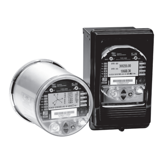
ION 8000 Series Models Socket Meter The socket meter is designed to fit into S-Base meter sockets and A-to-S Base adapters. The meter supports a number of different form factors including 9S, 35S, 36S, 39S, and 76S. Switchboard Meter The switchboard meter eliminates the need for shorting blocks. All voltage and current connections are made via terminals located on the rear of the switchboard case. -
Page 6: Meter Overview
Meter Overview Master Reset Demand pinhole (located Reset Switch under front label ALT/Enter button TEST mode button (located under front label) Navigation buttons Resets the peak demand values logged in the DEMAND RESET SWITCH meter. Can be activated with the cover on or off. Toggles between display modes. -
Page 7: Meter Labels
Meter Labels Test amps Voltage transformer ratio Class accuracy Current TYPE 8500 transformer ratio WATT Multifunction Watthour/Varhour Meter Test constant (LED pulse rate) Primary watthour constant Freq Class designation Mult by Transformer factor (VTR x CTR) -277 Serial number and Form factor ANSI bar code area Form factor... - Page 8 Before You Begin Familiarize yourself with the steps in this guide and read the safety precautions presented on the “Installation Considerations” page. ANGER Do not power up the meter until the current and voltage wiring is completed. Recommended Tools #1 and #2 Phillips screwdrivers Precision flat-head screwdriver Wire cutters / stripper Socket Meter Dimensions...
-
Page 9: Step 1: Mount The Meter
Step 1: Mount the Meter Review the steps in this section before installing the meter, and determine the types of revenue sealing devices that you want to use before installing the meter. Examine the meter’s label to verify its service type matches your intended application. - Page 10 Switchboard Meter Mounting Prepare a mounting hole for the switchboard case. 149mm [5.9"] 141mm [5.6"] Place the switchboard case into the prepared mounting hole. Attach the mounting washers and nuts. Place the case cover into position and tighten the thumbscrew. Apply anti- tamper sealing if required.
-
Page 11: Step 2: Wire The Ground Terminal
Step 2: Wire the Ground Terminal AUTION The meter must be installed with an adequate chassis ground connection. Failure to properly connect the meter chassis ground voids the meter warranty. Do not use metal door hinges as a ground path. Meter Type Chassis Ground Connection Wire Size... -
Page 12: Step 3: Wire The Onboard I/O
Step 3: Wire the Onboard I/O Form C Digital Outputs (Ordering Option) Internal Digital Input Excitation Form C outputs (4) Type C-1, C-2, C-3, C-4 supported through meter Max Load Voltage 200 VAC/VDC Max Load Current 100 mA 30 Ω typical, 50 Ω maximum ON Resistance 400M Ω... - Page 13 Form A Digital Inputs (Ordering Option) Internal Digital Input Excitation Type Self-excited (internal 30 Vdc supply) Wire Use wiring appropriate for the application. Min. Pulse Width 20 ms Max. Input Transition Rate 50 per second Scan Time 20 ms Timing Resolution 1 ms, with 2 ms accuracy ON for external resistance of 2 kΩ...
- Page 14 External Digital Input Excitation Voltage Range 24 to 130 Vdc (external) Min. Pulse Width 20 ms Max. Input Transition Rate 50 per second Scan Time 20 ms Timing Resolution 1 ms, with 2 ms accuracy ON for external resistance of 2 kΩ or less OFF Inputs for external resistance of 20 MΩ...
- Page 15 Remove one jumper block, and place the other jumper block on pins 2 and 3 of the four-pin header (as shown in diagram). To use an external power supply for digital inputs, set jumpers as shown. Jumper blocks: If you want to use internal 30 Vdc supply for self-excitation, use this factory default setting.
-
Page 16: Step 4: Wire The Voltage And Current Inputs
Step 4: Wire the Voltage and Current Inputs Form 9 and 9S (3 element) I31 I11 Vref Form 9S diagram viewed from Form 9 diagram viewed front of socket (see below) from rear of switchboard Meter Chassis Meter Vref Ground Chassis Ground Front of socket... - Page 17 Connect G terminal to ground for AC power source. AUTION BEFORE performing an installation using the above 9S, 4-Wire Delta wiring configuration, see the Red/High Leg Delta technical note (available for download from the Power Measurement website) for important details.
- Page 18 Form 35 and 35S, 4-Wire Wye, 2 PTs, 3 CTs* For auxiliary-powered meters only. Connect G terminal to ground for AC power source. * This configuration can affect some of the meter’s parameter calculations. Contact Power Measurement for details.
- Page 19 Form 35 and 35S, 3-Wire Delta, No PTs, 2 CTs AUTION The pinout silhouette below is specific to Form 35S, 3-Wire Delta, No PTs, 2 CTs. Ensure Vref is not connected to ground. Form 35 diagram viewed 35S diagram viewed from from rear of switchboard front of socket Leave...
- Page 20 Form 36 and 36S (2½-element) 36S diagram viewed from Form 36 diagram viewed front of socket (see below) from rear of switchboard Front of socket Back of VOLTS MODE = 36S-4 Wire Wye Leave (wiring view) meter unconnected 57 - 277 V L-N See “Phasor Diagrams”...
- Page 21 Form 39S (3 element; I4 optional) See “Phasor Diagrams” on page 35 to verify meter operation. Vref 39S diagram viewed from Front of socket Back of front of socket (see right) (wiring view) meter I 2 2 Meter Chassis Ground VOLTS MODE = 9S 4 Wire Wye/Delta 57 - 277 V L-N I4 optional input for ION 8400 / ION 8500 meters only...
- Page 22 Form 76S See “Phasor Diagrams” on page 35 to verify meter operation. Vref 76S diagram viewed from Front of socket Back of front of socket (see right) (wiring view) meter Meter Chassis Ground VOLTS MODE = 36S 4 Wire Wye 57 - 277 V L-N I4 optional input for ION 8400 / ION 8500 meters only Form 76S 4-Wire Wye, 2 PTs, 4 CTs...
- Page 23 Voltage Inputs Inputs (9S/39S) Va, Vb, Vc, Vref (35S) Vab, Vcb, Vref (36S/76S) Va, Vc, Vref Connector Type Ring or split ring connector Wire 3.3 to 2.1 mm (12 to 14 AWG) Steady Ste (9S/36S/39S/76S) Standard 57-277 (+/-15%) VLN rms 120 - 277 (+/-20%) VLN rms (standard) for 6 hours max Overload (9S/36S/39S/76S)
- Page 24 Current Inputs: Standard Inputs Ia, Ib, Ic, I neutral (39S/76S only) Connector Type Ring or split ring connector Wire Gauge 3.3 to 2.1 mm (12 to 14 AWG) Starting Current 0.005 A RMS (In=1 A; Imax=20 A) Overrange to 50A RMS Input Rating 0.05/20A RMS Overload...
- Page 25 Using Potential Transformers System Mode Voltage Range Requires PTs 120 VAC L-N or 208 VAC L-L 277 VAC L-N or 480 VAC L-L 347 VAC L-N or 600 VAC L-L over 347 VAC L-N or 600 VAC L-L 120 VAC L-N or 240 VAC L-L 277 VAC L-N or 554 VAC L-L Single Phase over 277 VAC L-N or 554 VAC L-L...
-
Page 26: Step 5: Wire The Communications
Step 5: Wire the Communications RJ45 RJ11 or RJ31 10Base-T (RJ45) Category 3 UTP (min.) Optional Modem RJ11 or RJ31on COM2 Pin 1 = Transmit Data + FCC part 68 telephone cord Pin 2 = Transmit Data - RJ11 (6 pin) Pin 3 = Receive Data + Pin 3 = Ring (RJ11) Pin 6 = Receive Data -... - Page 27 Switchboard Meter Wire Cluster Molex Pin Assignments Wire Colors Function COM 2 Data+ or COM 4 Data+ White/Blue or inactive COM 2 Data– or COM 4 Data– or Blue/White inactive Black/Blue For I/O Expander—Do not Use Black COM 1 RS-232 CTS White COM 1 RS-232 CD COM 1 RS-232 RXD...
- Page 28 Communications Options Standard = Selectable RS-232 or RS-485 (COM1), High Speed RS-485 (COM2), ANSI 12.13 Type II Optical (COM3) Socket meters are available with either Fiber or Ethernet, not both. ION 8500/ION 8400 COM1 COM2 COM3 COM4 Network IRIG-B RS-232 –...
- Page 29 Insert the wire and remove the screwdriver to clamp the spring on the wire. COMs on the I/O box are not connected. Use the RS-485 and RS-232 provided on the breakout panel. ION 8300 COM 1 COM 2 COM 3...
-
Page 30: Step 6: Wire The Power Supply
COM 1 COM 2 COM 3 Network IRIG-B Available with Onboard I/O provided no Fibre Outage Dialback is present. Not available if internal EtherGate modem option on this port Internal Modem Modem- Gate Socket meter only. Optional IRIG-B GPS Time Synchronization IRIG-B cannot be configured via the meter’s front panel. -
Page 31: Step 7: Power Up The Meter
Power Supply Specifications Standard power supply (120 to 277 VAC): the meter is powered up when the voltage inputs are applied in Step #7. Standard low voltage power supply (57 to 70 VAC): the meter is powered up when the voltage inputs are applied in Step #7. Regular auxiliary power pigtail (160 to 277 VAC): connect the power plug to the 160 to 277 VAC source or the 200 to 350 VDC source. - Page 32 Set up the following: Menu Setting Description Range (Values) Default 9S 4W-WYE/DELTA The power system’s configuration 35S 3 Wire Volts Mode 4W-WYE – WYE, DELTA, etc. 36S 4 W-WYE DEMO The Potential Transformer’s PT Primary 1 to 999,999,999 primary winding voltage rating The Potential Transformer’s PT Secondary 1 to 999,999,999...
- Page 33 Menu Setting Description Range (Values) Default ION, Modbus RTU, Modbus Master, DNP v3.00, ModemGate, GPS: Truetime/Datum Protocol Specifies which protocol is active GPS: Arbiter GPS: Arbiter/Vorne Factory EtherGate Specifies COM port baud rate Baud Rate 300 - 115200 9600 during serial communications Specifies the meter’s transmit Transmit Delay 0 - 1.0...
- Page 34 Menu Setting Description Range (Values) Default 000.000.000.000 to IP Address Specifies TCP/IP Ethernet address None 999.999.999.999 Subnet Mask Specifies Subnet Mask 0.0.0.0 to 255.255.255.0 None Specifies Ethernet gateway (if 000.000.000.000 to Gateway None used) 999.999.999.999 IP Boot Option Specifies IP Boot Option Manual, BootP Manual 000.000.000.000 to...
-
Page 35: Step 9: Verify Meter Operation
Step 9: Verify Meter Operation The LEDs on the side of the meter flash during communications. C O M R X D C O M T X D R X D M O D T X D A S E 1 0 B IV IT A C T... - Page 36 WYE - ACB Rotation Applicable Volts Mode = 9S 4W Wye/Delta and 36S 4W WYE Q2: Leading PF (+) Q1: Lagging PF (-) Active Power Active Power Q3: Lagging PF (-) Q4: Leading PF (+) 3 Wire Delta - ABC Rotation Applicable Volts Mode = 35S 3Wire Q2: Leading PF (+) Q1: Lagging PF (-)
- Page 37 3 Wire Delta - ACB Rotation Applicable Volts Mode = 35S 3-Wire Q2: Leading PF (+) Q1: Lagging PF (-) Active Power Active Power Q3: Lagging PF (-) Q4: Leading PF (+) 2 Element (3 Wire) Delta - ABC Rotation (2 PT, 3CT) Applicable Volts Mode = 35S 3 Wire (firmware versions v22x to v24x) Q2: Leading PF (+) Q1: Lagging PF (-)
- Page 38 2 Element (3 Wire) Delta - ACB Rotation (2 PT, 3CT) Applicable Volts Mode = 35S 3 Wire (firmware versions v22x to v24x) Q2: Leading PF (+) Q1: Lagging PF (-) Active Power Active Power Q3: Lagging PF (-) Q4: Leading PF (+) 2 Element (3 Wire) Delta - ABC Rotation (2 PT, 2CT) Applicable Volts Mode = 35S 3 Wire (firmware versions previous to v22x) Q2: Leading PF (+)
- Page 39 2 Element (3 Wire) Delta - ACB Rotation (2 PT, 2CT) Applicable Volts Mode = 35S 3 Wire Q2: Leading PF (+) Q1: Lagging PF (-) Active Power Active Power Q3: Lagging PF (-) Q4: Leading PF (+) 4 Wire Delta (High/Red Leg Delta) ION Meter Phasor diagram in 9S / 4WYE ION Meter Phasor diagram in 9S / 4WYE mode at UNITY PF.
-
Page 40: Step 10: View Meter Data
Step 10: View Meter Data NORM mode Use the Up and Down buttons to scroll through NORM mode display screens. NORM Screen Contents kWh delivered/received kVARh kVARh delivered/received kVAh kVAh delivered/received Peak Demand Delivered Maximum delivered kW value (timestamped) Peak Demand Received Maximum received kW value (timestamped) Peak Demand Reset Number of Demand Resets (timestamped) - Page 41 TOU Display Screens Contents kWh delivered values for each TOU rate TOU Energy by Rate Maximum kW delivered for each TOU rate kW Peak Demand kWh delivered in PB Previous Billing Energy Maximum kW delivered in PB Prev Billing Peak Demand kWh delivered for each TOU rate in PB Previous Season Energy Max kW delivered for each TOU rate in PB...
- Page 44 For further assistance please contact us at: Worldwide Headquarters 2195 Keating Cross Road Saanichton, BC Canada V8M 2A5 Tel: 1-250-652-7101 Fax: 1-250-652-0411 Email: support@pwrm.com www.pwrm.com © 2005 Power Measurement Printed in Canada MRP: 70000-0206-13 Revision Date: June 2006...
Need help?
Do you have a question about the ION 8300 and is the answer not in the manual?
Questions and answers